Mitsubishi Electric FR-E700 Instruction Manual
Hide thumbs
Also See for FR-E700:
- Instruction manual (538 pages) ,
- Basic instruction manual (149 pages) ,
- Installation manuallines (38 pages)

Related Manuals for Mitsubishi Electric FR-E700


Summary of Contents for Mitsubishi Electric FR-E700
- Page 1 FR-E700 Inverters Instruction Manual FR-E720S SC EC/ENE FR-E740 SC EC/ENE Art.No. 412411 INDUSTRIAL AUTOMATION 30012019 Version B Versionsprüfung...
- Page 3 Changes / Additions / Corrections 05/2011 akl/rwi — 01/2019 Additions: FR-E700 SC ENE (Ethernet communication function built-in type) Symbols used in the manual Changes: The positive (source) control logic is given priority in all descriptions, diagrams etc. General correction of version A...
- Page 5 Thank you for choosing this Mitsubishi inverter. This instruction manual provides instructions for advanced use of the FR-E700 SC series inverters. In- correct handling might cause an unexpected fault. Before using the inverter, always read this instruc- tion manual to use the equipment to its optimum.
- Page 6 Electric Shock Prevention WARNING: ● While power is on or when the inverter is running, do not open the front cover. Otherwise you may get an electric shock. ● Do not run the inverter with the front cover removed. Otherwise, you may access the exposed high-voltage terminals or the charging part of the circuitry and get an electric shock.
- Page 7 ● Always make sure that polarity is correct to prevent damage, etc. Otherwise, burst, damage, etc. may occur. ● While power is on or for some time after power-off, do not touch the inverter as it is hot and you may get burnt. FR-E700 SC EC/ENE...
- Page 8 ● As the inverter is a precision instrument, do not drop or subject it to impact. ● If halogen-based materials (fluorine, chlorine, bromine, iodine, etc.) infiltrate into a Mitsubishi Electric product, the product will be damaged. Halogen-based materials are often included in fumigant, which is used to sterilize or disinfect wooden packages. When...
- Page 9 ● Do not modify the equipment. ● Do not perform parts removal which is not instructed in this manual. Doing so may lead to fault or damage of the inverter. FR-E700 SC EC/ENE...
- Page 10 CAUTION: ● The electronic thermal relay function does not guarantee protection of the motor from overheating. It is recommended to install both an external thermal and PTC thermistor for overheat protection. ● Do not use a magnetic contactor on the inverter input for frequent starting/stopping of the inverter.
- Page 11 Many of the diagrams and drawings in instruction manuals show the inverter without a cover, or par- tially open. Never run the inverter in this status. Always replace the cover and follow this instruction manual when operating the inverter. FR-E700 SC EC/ENE...
- Page 12 Symbols used in the manual Use of instructions Instructions concerning important information are marked separately and are displayed as follows: NOTE Text of instruction Use of examples Examples are marked separately and are displayed as follows: Example Example text Use of numbering in the figures Numbering within the figures is displayed by white numbers within black circles and is explained in a table following it using the same number, e.g.: Use of handling instructions...
-
Page 13: Table Of Contents
Connecting the parameter unit using a connection cable ....3-30 3.5.2 Connection to the PU connector at FR-E700 SC ENE ......3-31 3.5.3 RS-485 communication . - Page 14 Contents Connection of stand-alone option units ..........3-37 3.8.1 Magnetic contactors (MC).
- Page 15 Applied motor (Pr. 71, Pr. 450)..........6-87 6.8.3 To exhibit the best performance of the motor performance (offline auto tuning) (Pr. 71, Pr. 80 to Pr. 84, Pr. 90 to Pr. 94, Pr. 96, Pr. 859). . . 6-90 FR-E700 SC EC/ENE...
- Page 16 Contents Motor brake and stop operation ..........6-100 6.9.1 DC injection brake (Pr.
- Page 17 (FR-E700 SC ENE) ............6-283 6.19.7 MELSOFT / FA product connection (FR-E700 SC ENE) ..... . 6-291 6.19.8 USB communication (Pr.
- Page 18 Contents Troubleshooting List of alarm display ..............7-2 Causes and corrective actions .
- Page 19 SERIAL number check ........... . A-26 FR-E700 SC EC/ENE...
- Page 20 Contents...
-
Page 21: Product Checking And Part Identification
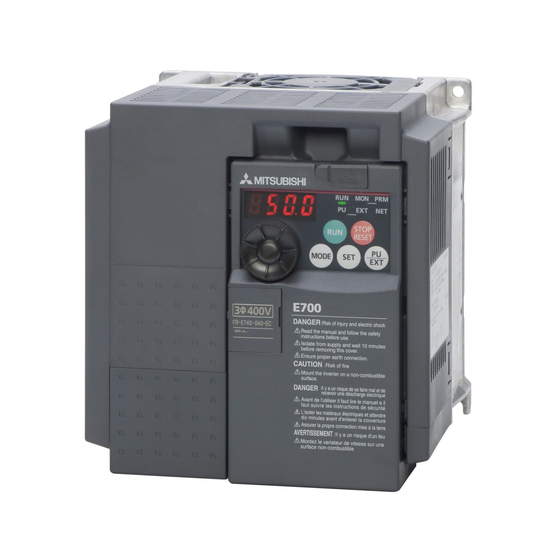
- 016 SC - Symbol Voltage Class Symbol Type Number Symbol Function E720S Single-phase 230 V Ethernet 3-digit display communication E740 Three-phase 400 V Standard FR-E700SC-ENE-Product identification Fig. 1-1: Inverter type FR-E700 SC EC/ENE FR-E700 SC EC/ENE 1 - 1... -
Page 22: Description Of The Case
Inverter type Serial number I002121E Fig. 1-2: Appearance and structure of FR-E700 SC EC Location of the capacity plate and the rating plate differs according to the inverter capacity. Refer to the outline dimension drawing. (Refer to section A.3.) NOTE For removal and reinstallation of covers, refer to section 2.1. -
Page 23: E700 Sc Ene
Output rating FR-E740-016SC-ENE Inverter model SERIAL Serial number SAMPLE Serial number Country of origin MADE IN JAPAN FR-E700SC-ENE-parts identification Fig. 1-3: Appearance and structure of FR-E700 SC ENE Sym- Refer to Sym- Refer to Name Name section section ³ ¾... -
Page 24: Accessory
Description of the case Product checking and part identification 1.2.3 Accessory Fan cover fixing screws Capacity Screw Size [mm] Number FR-E720S-050SC to 110SC M3 35 FR-E740-040SC to 095SC M3 35 FR-E740-120SC to 300SC M3 35 Tab. 1-2: Fan cover fixing screws NOTES Inverters FR-E720S-008SC to 030SC and FR-E740-026SC or less are not provided with the cooling fan. -
Page 25: Installation
Example: FR-E740-095SC I002050E Fig. 2-1: Removal of the front cover Reinstallation To reinstall, match the cover to the inverter front and install it straight. Example: FR-E740-095SC I001908E Fig. 2-2: Reinstallation of the front cover FR-E700 SC EC/ENE 2 - 1... -
Page 26: Fr-E740-230Sc And Fr-E740-300Sc
Removal and reinstallation of the front cover Installation 2.1.2 FR-E740-230SC and FR-E740-300SC Removal Loosen the installation screws of the front cover 1. Remove the front cover 1 by pulling it toward you in the direction of arrow. Remove the front cover 2 by pulling it toward you in the direction of arrow (refer to the figure below). Example: FR-E740-230SC Loosen the screw Remove front cover 1... - Page 27 The same serial number is printed on the capacity plate of the front cover and the rating plate of the inverter. Before reinstalling the front cover, check the serial numbers to ensure that the cover removed is reinstalled to the inverter from where it was removed. FR-E700 SC EC/ENE 2 - 3...
-
Page 28: Removal And Reinstallation Of The Wiring Cover
Removal and reinstallation of the wiring cover Installation Removal and reinstallation of the wiring cover The cover can be removed easily by pulling it toward you. To reinstall, fit the cover to the inverter along the guides. FR-E720S-050SC to 110SC FR-E720S-008SC to 030SC FR-E740-016SC to 095SC Guides... -
Page 29: Mounting
FR-E740-016SC or more Front cover Front cover Wiring cover Wiring cover I002150E Fig. 2-6: Installation of the FR-E700 SC EC on the panel FR-E720S-008SC to 030SC FR-E720S-050SC or more, FR-E740-016SC or more Front cover Front cover Wiring cover Wiring cover... - Page 30 Mounting Installation NOTE When encasing multiple inverters, install them in parallel as a cooling measure. Leave enough clearances around the inverter (refer to page 2-11). Fig. 2-8: Good heat dissipation is achieved through the vertical alignment of the frequency inverter, the side-by-side mounting and maintenance of minimum clearances.
-
Page 31: Enclosure Design
Temperature applicable for a short time, e.g. in transit. Temperature The permissible ambient temperature of the inverter FR-E700 SC is between 10 and +50 °C. Always operate the inverter within this temperature range. Operation outside this range will considerably shorten the service lives of the semiconductors, parts, capacitors and others. Take the following meas- ures so that the ambient temperature of the inverter falls within the specified range. - Page 32 Enclosure design Installation Humidity Normally operate the inverter within the 45 to 90% range of the ambient humidity. Too high humidity will pose problems of reduced insulation and metal corrosion. On the other hand, too low humidity may produce a spatial electrical breakdown. The insulation distance specified in JEM1103 "Control Equipment Insulator"...
- Page 33 Especially when impact is imposed repeatedly, caution must be taken as the part pins are likely to break. ● Countermeasures – Provide the enclosure with rubber vibration isolators. – Strengthen the structure to prevent the enclosure from resonance. – Install the enclosure away from sources of vibration. FR-E700 SC EC/ENE 2 - 9...
- Page 34 Enclosure design Installation Cooling system types for inverter enclosure From the enclosure that contains the inverter, the heat of the inverter and other equipment (trans- formers, lamps, resistors, etc.) and the incoming heat such as direct sunlight must be dissipated to keep the in-enclosure temperature lower than the permissible temperatures of the in-enclosure equipment including the inverter.
-
Page 35: Inverter Placement
Mount the inverter on a wall as specified. Do not mount it horizontally or any other way. Above the inverter Heat is blown up from inside the inverter by the small fan built in the unit. Any equipment placed above the inverter should be heat resistant. FR-E700 SC EC/ENE 2 - 11... - Page 36 Enclosure design Installation Arrangement of multiple inverters When multiple inverters are placed in the same enclosure, generally arrange them horizontally as shown in the figure (a). When it is inevitable to arrange them vertically to minimize space, take such measures as to provide guides since heat from the bottom inverters can increase the temperatures in the top inverters, causing inverter failures.
-
Page 37: Wiring
Select the reactor according to the model. Remove the jumpers across terminals P/+ FFR-DT = Output filter and P1 to connect to the DC reactor. (Refer to section 3.8.6). FFR-SI = Sine wave filter I002122E_N Fig. 3-1: System configuration overview FR-E700 SC EC/ENE 3 - 1... - Page 38 Inverter and peripheral devices Wiring NOTES The life of the inverter is influenced by ambient temperature. The ambient temperature should be as low as possible within the permissible range. Especially when mounting the inverter inside an enclosure, take cautions of the ambient temperature. (Refer to section 2.4.2.) Wrong wiring might lead to damage of the inverter.
-
Page 39: Peripheral Devices
When the breaker on the inverter primary side trips, check for the wiring fault (short circuit), dam- age to internal parts of the inverter, etc. Identify the cause of the trip, then remove the cause and power on the breaker. FR-E700 SC EC/ENE 3 - 3... -
Page 40: Terminal Connection Diagram
"4" in any of Pr. 178 to Pr. 184 (input terminal switch function selection)to assign the function, and turn ON AU signal. Connector for plug-in Option connector option connection I002123E Fig. 3-3: Terminal connection diagram of the inverter FR-E700 SC EC 3 - 4... -
Page 41: E700 Sc Ene
Voltage/current input Pr. 178 to Pr. 184 (input terminal function selection)to assign the switch function, and turn ON AU signal. Ethernet connector I002123E_ENE Fig. 3-4: Terminal connection diagram of the inverter FR-E700 SC ENE FR-E700 SC EC/ENE 3 - 5... - Page 42 Terminal connection diagram Wiring NOTES To prevent a malfunction due to noise, keep the signal cables more than 10 cm away from the power cables. Also separate the main circuit wire of the input side and the output side. After wiring, wire offcuts must not be left in the inverter. Wire offcuts can cause an alarm, failure or malfunction.
-
Page 43: Main Circuit Connection
When using single-phase power input, terminals are L1, N. Indicated as "+" on the terminal block of the single-phase power input model. Indicated as "–" on the terminal block of the single-phase power input model. FR-E700 SC EC/ENE 3 - 7... -
Page 44: Terminal Layout And Wiring
Main circuit connection Wiring 3.3.2 Terminal layout and wiring Single-phase, 200 V class FR-E720S-008SC to 030SC FR-E720S-050SC to 110SC Jumper Jumper Screw size (M3.5) Screw size (M4) Screw size Screw size (M3.5) (M4) L1 N Motor L1 N Power supply Motor Power supply I002033E... - Page 45 ● Connect the motor to U, V, W. At this time, turning on the forward rotation switch (signal) rotates the motor in the counter clockwise direction when viewed from the motor shaft. FR-E700 SC EC/ENE 3 - 9...
- Page 46 Main circuit connection Wiring Cables and wiring length Select the recommended cable size to ensure that a voltage drop will be 2% max. If the wiring distance is long between the inverter and motor, a main circuit cable voltage drop will cause the motor torque to decrease especially at the output of a low frequency.
- Page 47 A screw that has been tightened too tightly can cause a short circuit or malfunction due to the unit breakage. ● Use crimping terminals with insulation sleeve to wire the power supply and motor. FR-E700 SC EC/ENE 3 - 11...
- Page 48 Main circuit connection Wiring Notes on earthing CAUTION: Leakage currents flow in the inverter or the EMC filter respectively. To prevent an electric shock, the inverter, input filter and motor must be earthed. (This inverter must be earthed. Earthing must conform to the requirements of national and local safety regulations and electrical codes. (JIS, NEC section 250, IEC 536 class 1 and other applicable standards)).
- Page 49 3.7 kW the 500 m permissible wiring length is exceeded by the two parallel motor lead wires. 300 m 300 m I001904E 300 m + 300 m = 600 m FR-E700 SC EC/ENE 3 - 13...
- Page 50 Main circuit connection Wiring When driving a 400 V class motor by the inverter, surge voltages attributable to the wiring constants may occur at the motor terminals, deteriorating the insulation of the motor. Take the following meas- ures in this case. Use a "400 V class inverter-driven insulation-enhanced motor"...
-
Page 51: Control Circuit Specifications
When contacts Safe stop input shortening wire and connect the safety relay are shortcir- (Channel 2) module when using the safety stop function. cuited: 4 to 6 mA DC Tab. 3-9: Input signals (1) FR-E700 SC EC/ENE 3 - 15... - Page 52 Control circuit specifications Wiring Rated Refer to Terminal Name Description Specifications Page Used as power supply when connecting potenti- ometer for frequency setting (speed setting) from 5.2 V DC ± 0.2 V, Frequency setting outside of the inverter. (Output Permissible load voltage power supply Rated output voltage: 5 V DC...
- Page 53 Communication with network devices can be 100BASE-TX/10BASE-T made via Ethernet by connecting an Ethernet Ethernet connector Transmission speed: 3-34 cable to the Ethernet connector on the Ethernet 10 or 100 Mbps board. Connector: RJ45 Tab. 3-11: Communication signals FR-E700 SC EC/ENE 3 - 17...
-
Page 54: Control Circuit Terminals
Control circuit specifications Wiring 3.4.1 Control circuit terminals Recommended wire size: 0.3 mm to 0.75 mm S1 S2 I002125E Fig. 3-7: Terminal layout Wiring method Use a bar terminal and a cable with a sheath stripped off for the control circuit wiring. For a single wire, strip off the sheath of the cable and apply directly. - Page 55 Wire Size [mm²] Blade Terminal Poduct Number Insulation Product Number Crimping Tool 0.3 to 0.75 BT 0.75-11 VC 0.75 NH 69 Tab. 3-13: Recommended bar terminals (Maker: NICHIFU Co., Ltd, as of Jan. 2017) FR-E700 SC EC/ENE 3 - 19...
- Page 56 Control circuit specifications Wiring Insert the wire into a socket. Fig. 3-11: Cable connection I001986E When using a single wire or a stranded wire without a bar terminal, push an open/close button all the way down with a flathead screw driver, and insert the wire. Fig.
- Page 57 0.4x2.5 of Phoenix Contact Co., Ltd.). If a flathead screwdriver with a narrow tip is used, terminal block may be damaged. ● Place the flathead screwdriver vertical to the open/close button. In case the blade tip slips, it may cause to damage of inverter or injuries. FR-E700 SC EC/ENE 3 - 21...
- Page 58 Control circuit specifications Wiring Common terminals of the control circuits PC, 5, SE Terminals PC, 5, and SE are all common terminals (0 V) for I/O signals and are isolated from each other. Avoid connecting the terminal PC and 5 and the terminal SE and 5. Terminal PC is a common terminal for the contact input terminals (STF, STR, RH, RM, RL and RES).
-
Page 59: Wiring Instructions
(when the source logic is selected). ● Do not install an external power source in parallel with the internal 24 V DC power source (connected to terminals PC and SD) to use them together. FR-E700 SC EC/ENE 3 - 23... -
Page 60: Safety Stop Function
Control circuit specifications Wiring 3.4.3 Safety stop function The terminals related to the safety stop function are shown below. For the rated specification of each terminal refer to Tab. 3-9. Terminal Description Between S1 and PC / S2 and PC For input of safety stop channel 1. - Page 61 Fig. 3-16: Connecting the Safety relay module QS90SR2SN-Q of Mitsubishi NOTE Changing the terminal assignment using Pr. 190 to Pr. 192 (output terminal function selection) may affect the other functions. Set parameters after confirming the function of each terminal. FR-E700 SC EC/ENE 3 - 25...
- Page 62 Control circuit specifications Wiring Safety stop function operation Input Signal Internal Output Signal Inverter Operation Enable Input Power Safety Circuit Signal S1-PC S2-PC SAFE SAFE2 — — — Output shutoff (Safe state) No failure Drive enabled Short Short Failure Output shutoff (Safe state) No failure Output shutoff (Safe state) Open...
-
Page 63: Changing The Control Logic
(The output signals may be used in either the sink or source logic independently of the jumper con- nector position.) Fig. 3-18: Changing the control logic I002127E FR-E700 SC EC/ENE 3 - 27... - Page 64 Control circuit specifications Wiring NOTES Using the SOURCE/SINK jumper (and the particular connection of the PC/SD terminal as a refer- ence point), the input terminals can be changed between positive switching (source logic) or neg- ative switching (sink logic) depending on regional requirements. Turn off the inverter power before switching a jumper connector.
- Page 65 PC-SD as a 24 V DC power supply, do not install a power supply in parallel in the outside of the inverter. Doing so may cause a malfunction due to undesirable current.) Fig. 3-20: AY40 Inverter Using an external power supply in connection with the outputs of a PLC Current I001030E FR-E700 SC EC/ENE 3 - 29...
-
Page 66: Pu Connector
PU connector Wiring PU connector Using the PU connector, you can perform communication operation from the FR-PU07, the FR-PA07 or a personal computer. Refer to the figure below to open the PU connector cover. To open the cover Place a flathead screwdriver, etc. in a slot and push up the cover to open. -
Page 67: Connection To The Pu Connector At Fr-E700 Sc Ene
PU connector FR-E700SC-ENE PU connector Fig. 3-23: Access to the PU connector of the FR-E700 SC ENE 3.5.3 RS-485 communication When the PU connector is connected with a personal, FA or other computer by a communication ca- ble, a user program can run and monitor the inverter or read and write to parameters. -
Page 68: Usb Connector
USB connector Wiring USB connector Inverter setup can be easily performed using the FR Configurator by connecting the inverter and per- sonal computer with a USB cable (version 1.1). Specification Description Interface USB 1.1 Transmission speed 12 MBps Wiring length Connector USB mini B connector (receptacle mini B type) Power supply... -
Page 69: System Configuration For Ethernet Communication (Fr-E700 Sc Ene)
(FR-E700 SC ENE) 3.7.1 Ethernet communication overview The FR-E700 SC ENE inverter is equipped with an Ethernet board. Communication with network de- vices can be made via Ethernet by connecting an Ethernet cable to the Ethernet connector on the Ethernet board. -
Page 70: Ethernet Connector
Interface RJ-45 Number of interfaces available IP version IPv4 Tab. 3-17: Ethernet communication specifications of FR-E700 SC ENE Ethernet connector FR-E700SC-ENE Ethernet connector Fig. 3-26: Position of the Ethernet connector ● Connection cable Use Ethernet cables compliant with the following standards. -
Page 71: Led Indicator For Communication Status
Wiring System configuration for Ethernet communication (FR-E700 SC ENE) ● Handling of the Ethernet cable – Do not touch the conductors of the cable or the connector on the inverter. Keep the conduc- tors free of dust or dirt. Handling the conductors with oily hands or dust/dirt adhesion to the conductors may cause transmission losses and impair normal data link operation. -
Page 72: Removal Of The Ethernet Board
System configuration for Ethernet communication (FR-E700 SC ENE) Wiring 3.7.4 Removal of the Ethernet board The Ethernet board is installed in the initial status. Before wiring cables to the control circuit terminals or to the main circuit terminals on the FR-E740-170SC or lower or FR-E720S-050SC or lower inverter, remove the Ethernet board as follows. -
Page 73: Connection Of Stand-Alone Option Units
Since repeated inrush currents at power on will shorten the life of the converter circuit (switching life is about 1,000,000 times.), frequent starts and stops of the MC must be avoided. Turn on/off the inverter start controlling terminals (STF, STR) to run/stop the inverter. FR-E700 SC EC/ENE 3 - 37... - Page 74 Connection of stand-alone option units Wiring Example As shown below, always use the start signal (ON or OFF across terminals STF or STR-PC) to make a start or stop. (Refer to section 6.10.4.) Inverter Power To the supply motor Operation preparation Start/Stop Operation Start Stop...
-
Page 75: Connection Of A Dedicated External Brake Resistor Fr-Abr (Fr-E720S-030Sc Or More, Fr-E740-016Sc Or More)
● The shape of jumper differs according to capacities. FR-E720S-030SC Fig. 3-31: Jumper Connection of a brake resistor to the terminals + and PR for the inverter FR-E720S-030SC Terminal + Terminal PR I002036E Brake resistor FR-E700 SC EC/ENE 3 - 39... - Page 76 Connection of stand-alone option units Wiring FR-E720S-050SC to 110SC Fig. 3-32: Jumper Connection of a brake resistor to the terminals + and PR for the inverters FR-E720S-050SC to 110SC Terminal + Terminal PR I001923E Brake resistor FR-E740-016SC to 095SC Fig. 3-33: Connection of a brake resistor to the terminals P/+ Jumper and PR for the inverters FR-E740-016SC to...
- Page 77 ● Brake resistor can not be used with the brake unit (FR-BU2), high power factor converter (FR-HC), power supply regeneration converter (FR-CV), etc. ● Do not connect a resistor directly to the DC terminals P/+ and N/–. This could cause a fire. FR-E700 SC EC/ENE 3 - 41...
-
Page 78: Connection Of A Brake Unit Fr-Bu2
Connection of stand-alone option units Wiring 3.8.3 Connection of a brake unit FR-BU2 When connecting a brake unit to improve the brake capability at deceleration, make connection as shown below. Connection example with the GRZG type discharging resistor Discharging resistor Inverter Motor 3-phase AC... - Page 79 ● Do not remove a jumper across terminal P/+ and P1 except when connecting a DC reactor. NOTE Set "1" in Pr. 0 "Brake mode selection" of the FR-BU2 to use GRZG type discharging resistor. FR-E700 SC EC/ENE 3 - 43...
- Page 80 Connection of stand-alone option units Wiring Connection example with the FR-BR(-H) type resistor Inverter Motor 3-phase AC power supply 002045E Fig. 3-38: Connection with the brake unit FR-BU2 If the control contacts are only specified for 230 V control power you must install a transformer when using a 400 V power supply.
-
Page 81: Connection Of The High Power Factor Converter Fr-Hc
Use sink logic when the FR-HC is connected. The FR-HC cannot be connected when source logic (factory setting) is selected. Do not remove a jumper across terminal P/+ and P1 except when connecting a DC reactor. FR-E700 SC EC/ENE 3 - 45... -
Page 82: Connection Of The Power Regeneration Common Converter Fr-Cv
Connection of stand-alone option units Wiring 3.8.5 Connection of the power regeneration common converter FR-CV When connecting the power regeneration common converter (FR-CV), connect the inverter terminals (P/+, N/ ) and the terminals P/L+ and N/L– of the power regeneration common converter (FR-CV). Inverter Motor Power regeneration common... -
Page 83: Connection Of The Power Improving Dc Reactor Ffr-Hel-(H)-E
The wiring length between the FFR-HEL-(H)-E and inverter should be 5 m maximum and mini- mized. NOTE Use the same wire size as that of the power supply wire (R/L1, S/L2, T/L3). (Refer to page 3-10.) FR-E700 SC EC/ENE 3 - 47... -
Page 84: Electromagnetic Compatibility (Emc)
When the wiring length is long (50 m or more) for the 400 V class small-capacity model (FR-E700-170SC or less), the external thermal relay is likely to op- erate unnecessarily because the ratio of the leakage current to the rated motor current increases. - Page 85 The earth leakage breaker must be either a Mitsubishi earth leakage breaker (ELB, for harmonics and surges) or an ELB with breaker designed for harmonic and surge suppression that is approved for use with frequency inverters. FR-E700 SC EC/ENE 3 - 49...
- Page 86 Electromagnetic compatibility (EMC) Wiring Note on selecting a suitable power supply ELCB If your application requires by installation standards an RCD (residual current device) as up stream protection please select according to DIN VDE 0100-530 as following: Single phase inverter type A or B Three phase inverter only type B Additionally, when selecting a residual current device (RCD), leakage current caused by the mains fil- ter, the length of the shielded motor cable and the carrier frequency must be taken into consideration.
- Page 87 (except NV-ZHA), NV with AA neutral wire open-phase protection. The other models are designed for harmonic and surge suppression: NV-C/NV-S/MN series, NV30-FA, NV50-FA, BV-C2, earth leakage alarm breaker (NF-Z), NV-ZHA, NV-H. FR-E700 SC EC/ENE 3 - 51...
-
Page 88: Inverter-Generated Noises And Their Reduction Techniques
Electromagnetic compatibility (EMC) Wiring 3.9.2 Inverter-generated noises and their reduction techniques Some noises enter the inverter to malfunction it and others are radiated by the inverter to malfunction peripheral devices. Though the inverter is designed to be insusceptible to noises, it handles low-level signals, so it requires the following basic techniques. - Page 89 ... Path through power supply propagated noise cable Ground wire by leakage ... Path current I001048E Fig. 3-45: Noise propagation Telephone Sensor power supply Inverter Receiver Instrument Sensor Motor I001049E Fig. 3-46: Noise paths FR-E700 SC EC/ENE 3 - 53...
- Page 90 Electromagnetic compatibility (EMC) Wiring Noise Measures Propagation Path When devices that handle low-level signals and are liable to malfunction due to noises, e.g. instru- ments, receivers and sensors, are contained in the enclosure that contains the inverter or when their signal cables are run near the inverter, the devices may be malfunctioned by air-propagated noises.
-
Page 91: Power Supply Harmonics
For power factor improvement, install a reactor on the inverter input side or in the DC circuit. FR-E700 SC EC/ENE 3 - 55... -
Page 92: Inverter-Driven 400 V Class Motor
Electromagnetic compatibility (EMC) Wiring 3.9.4 Inverter-driven 400 V class motor In the PWM type inverter, a surge voltage attributable to wiring constants is generated at the motor terminals. Especially for a 400 V class motor, the surge voltage may deteriorate the insulation. When the 400 V class motor is driven by the inverter, consider the following measures: ●... -
Page 93: Operation
When accessing the inverter for inspection, wait for at least 10 minutes after the power supply has been switched OFF, and then make sure that the voltage across the main circuit terminals P/+ and N/- of the inverter is no more than 30 V DC using a tester. FR-E700 SC EC/ENE 4 - 1... - Page 94 Precautions for use of the inverter Operation ● A short circuit or earth fault on the inverter output side may damage the inverter modules. – Fully check the insulation resistance of the circuit prior to inverter operation since repeated short circuits caused by peripheral circuit inadequacy or an earth fault caused by wiring inadequacy or reduced motor insulation resistance may damage the inverter modules.
- Page 95 However, decreasing current will result in insufficient torque and the inverter may not start. Therefore, choose the inverter which has enough allowance for current (up to 2 rank larger in capacity). ● Make sure that the specifications and rating match the system requirements. FR-E700 SC EC/ENE 4 - 3...
-
Page 96: Failsafe Of The System Which Uses The Inverter
Precautions for use of the inverter Operation 4.1.1 Failsafe of the system which uses the inverter When a fault occurs, the inverter trips to output a fault signal. However, a fault output signal may not be output at an inverter fault occurrence when the detection circuit or output circuit fails, etc. Al- though Mitsubishi assures best quality products, provide an interlock which uses inverter status out- put signals to prevent accidents such as damage to machine when the inverter fails for some reason and at the same time consider the system configuration where failsafe from outside the inverter, with-... - Page 97 For logic check, as same as the inverter running signal (RUN signal), the inverter outputs for the period from the inverter decelerates until output to the motor is stopped, configure a sequence considering the inverter deceleration time. FR-E700 SC EC/ENE 4 - 5...
- Page 98 Precautions for use of the inverter Operation Output terminal function assignment When using various signals, assign functions to Pr. 190 to Pr. 192 (output terminal function selection) referring to the table below. 190 to 192 Setting Output Signal Positive Logic Negative Logic Tab.
-
Page 99: Drive The Motor
When protecting the motor from overheat by the inverter, set Pr. 9 "Electronic thermal O/L relay". (Refer to section 5.1.1.) When the rated frequency of the motor is 60 Hz, set Pr. 3 "Base frequency" (Refer to section 5.1.2.) FR-E700 SC EC/ENE 4 - 7... -
Page 100: Operation Panel
Operation panel Operation Operation panel 4.3.1 Parts of the operation panel LED-Display 4-digit 7-segment display for operational values, parameter numbers, etc. Unit indication LED to indicate the current unit Hz: Frequency A: Current Off: Voltage Flicker: Set frequency Rotation direction indication Lit or flicker during inverter operation RUN is lit: Forward rotation RUN flickering slowly: Reverse rotation... - Page 101 EXT indication. (Press MODE simultaneously (0.5 s) or switch over change Pr. 79 setting to change to combined mode.) PU: PU operation mode EXT: External operation mode (Cancels PU stop also.) Tab. 4-3: Keys of the operation panel FR-E700 SC EC/ENE 4 - 9...
-
Page 102: Basic Operation (Factory Setting)
Operation panel Operation 4.3.2 Basic operation (factory setting) Operation mode switch over At powering on (external operation mode) PU Jog operation mode (Refer to page 4-16.) Example PU operation mode Value change and frequency flicker (output frequency monitor) Frequency setting has been written and completed! Output current monitor Output voltage monitor... -
Page 103: Easy Operation Mode Setting (Easy Setting Mode)
If the easy setting mode is terminated while Pr. 79 = "0" (initial setting), the operation mode switches between the PU operation mode and the External operation mode. Check the operation mode. Reset can be made with STOP/RESET. FR-E700 SC EC/ENE 4 - 11... - Page 104 Operation panel Operation Operation Method Operation Panel Operation Panel Indication Indication Start Command Frequency Command Flickering PU Modes Flickering Flickering External External (Analog signal at External operation mode (STF-, STR) terminal 2 (voltage) or 4 (current)) Flickering Flickering Combined operation External (STF-, STR) mode 1...
-
Page 105: Operation Lock
The STOP/RESET key is valid even in the operation lock status. Set "0" (extended mode parameter valid) in Pr. 160 "User group read selection". Set "10" or "11" (key lock mode valid) in Pr. 161 "Frequency setting/key lock operation selection". FR-E700 SC EC/ENE 4 - 13... - Page 106 Operation panel Operation Operation Display Screen at powering on The monitor display appears. PU indication is lit. Press the PU/EXT key to choose the PU operation mode. PRM indication is lit. Press the MODE key to choose the parameter setting mode. The parameter number read previously appears.
-
Page 107: Monitoring Of Output Current And Output Voltage
Appears when PU operation mode or external/PU combined operation mode 1 is selected (Pr. 79 = "3"). Push the digital dial to display the set frequency currently set. Fig. 4-11: Display the set frequency currently set I001067E FR-E700 SC EC/ENE 4 - 15... -
Page 108: Change The Parameter Setting Value
Operation panel Operation 4.3.8 Change the parameter setting value Example Change the Pr. 1 "Maximum frequency" setting from 120 Hz to 50 Hz. Operation Display Screen at powering on The monitor display appears. PU indication is lit. Press the PU/EXT key to choose the PU operation mode. -
Page 109: Parameter Clear/All Parameter Clear
– The inverter is not in the PU operation mode. Press the PU/EXT key. The PU indication is lit and the monitor (4 digit LED) displays "1". (When Pr. 79 = "0" (initial value)). Carry out operation from step again. FR-E700 SC EC/ENE 4 - 17... -
Page 110: Initial Value Change List
Operation panel Operation 4.3.10 Initial value change list Displays and sets the parameters changed from the initial value. NOTES Calibration parameters (C1 (Pr. 901) to C7 (Pr. 905)) are not displayed even they are changed from the initial settings. Only simple mode parameter is displayed when simple mode is set (Pr. 160 = 9999). Only user group is displayed when user group is set (Pr. - Page 111 Pressing the SET key in status "P.---" returns to the parameter setting mode. Turning the digital dial sets other parameters. Pressing the SET key displays the change list again. I001743E Fig. 4-14: Initial value change list FR-E700 SC EC/ENE 4 - 19...
- Page 112 Operation panel Operation 4 - 20...
-
Page 113: Basic Settings
FR-E720S-080SC and 110SC, FR-E740-040SC to 095SC FR-E740-120SC and 170SC FR-E740-230SC and 300SC Initial values differ according to the inverter capacity: 5 s: FR-E720S-110SC or less, FR-E740-095SC or less 10 s: FR-E740-120SC and 170SC 15 s: FR-E740-230SC and 300SC FR-E700 SC EC/ENE 5 - 1... -
Page 114: Overheat Protection Of The Motor By The Inverter
Simple mode parameter list Basic settings 5.1.1 Overheat protection of the motor by the inverter Set this parameter when using a motor other than the Mitsubishi standard motor (SF-JR) and Mitsubishi constant torque motor (SF-HRCA). Set the rated motor current in Pr. 9 "Electronic thermal O/L relay"... - Page 115 A special motor cannot be protected by the electronic thermal relay function. Use an external thermal relay. Electronic thermal relay does not work when 5% or less of inverter rated current is set to electronic thermal relay setting. FR-E700 SC EC/ENE 5 - 3...
-
Page 116: When The Rated Motor Frequency Is 60 Hz (Pr. 3)
Simple mode parameter list Basic settings 5.1.2 When the rated motor frequency is 60 Hz (Pr. 3) First, check the motor rating plate. If a frequency given on the rating plate is "60 Hz" only, always set Pr. 3 "Base frequency" to "60 Hz". Leaving the base frequency unchanged from "50 Hz" may make the voltage low and the torque insufficient. -
Page 117: Increase The Starting Torque (Pr. 0)
(The guideline is for about 10% change at the greatest.) Fig. 5-3: Relation between output frequency and output voltage Setting range Pr. 0, Pr. 46 Base frequency Output frequency [Hz] I001098E FR-E700 SC EC/ENE 5 - 5... - Page 118 Simple mode parameter list Basic settings Operation Display Screen at powering on The monitor display appears. PU indication is lit. Press the PU/EXT key to choose the PU operation mode. PRM indication is lit. Press the MODE key to choose the parameter setting mode.
-
Page 119: Limit The Maximum And Minimum Output Frequency (Pr. 1, Pr. 2)
Output Minimum and maximum output frequency frequency [Hz] Clamped at the maximum frequency Pr. 1 Pr. 18 Frequency setting Pr. 2 5, 10 V (4 mA) (20 mA) Clamped at the minimum frequency I001100E FR-E700 SC EC/ENE 5 - 7... - Page 120 Simple mode parameter list Basic settings Operation Display Screen at powering on The monitor display appears. PU indication is lit. Press the PU/EXT key to choose the PU operation mode. PRM indication is lit. Press the MODE key to choose the parameter setting mode.
-
Page 121: Change The Acceleration/Deceleration Time (Pr. 7, Pr. 8)
Too short acceleration/deceleration times may lead to an inverter shutoff with error message (E.THT, E.THM, E.OCT, E.OVT ...). Example Change the Pr. 7 "Acceleration time" setting from "5 s" to "10 s". Fig. 5-7: Acceleration/deceleration time I000006C FR-E700 SC EC/ENE 5 - 9... - Page 122 Simple mode parameter list Basic settings Operation Display Screen at powering on The monitor display appears. PU indication is lit. Press the PU/EXT key to choose the PU operation mode. PRM indication is lit. Press the MODE key to choose the parameter setting mode.
-
Page 123: Operation Mode (Pr. 79)
6.10.1. When the X12 signal is not assigned, function of the MRS signal switches from MRS (output stop) to PU operation interlock signal. NOTE Setting value "1" to "4" can be changed in the easy operation mode. (Refer to section 4.3.3.) FR-E700 SC EC/ENE 5 - 11... -
Page 124: Large Starting Torque And Low Speed Torque Are Necessary
Simple mode parameter list Basic settings 5.1.7 Large starting torque and low speed torque are necessary (Advanced magnetic flux control, General-purpose magnetic flux vector control) (Pr. 71, Pr. 80, Pr. 81, Pr. 800) AD MFVC AD MFVC AD MFVC GP MFVC GP MFVC GP MFVC Advanced magnetic flux vector control can be selected by setting the capacity, poles and type of the... - Page 125 Uneven rotation slightly increases as compared to the V/F control. (It is not suitable for machines such as grinding machine and wrapping machine which requires less uneven rotation at low speed.) Use Pr. 89 to adjust the motor speed fluctuation at load fluctuation. (Refer to page 6-38.) FR-E700 SC EC/ENE 5 - 13...
- Page 126 Simple mode parameter list Basic settings Selection method of general-purpose magnetic flux vector control Perform secure wiring. (Refer to section 3.2.) Set the motor. (Pr. 71) (Refer to page 5-12.) Motor Pr. 71 Remarks SF-JR Initial value Standard motor, SF-HR —...
-
Page 127: To Exhibit The Best Performance Of The Motor Performance
Reading/writing/copy of motor constants tuned by offline auto tuning are enabled. The offline auto tuning status can be monitored with the operation panel and PU (FR-PU04/ FR-PU07). FR-E700 SC EC/ENE 5 - 15... - Page 128 Simple mode parameter list Basic settings Before performing offline auto tuning ● Make sure advanced magnetic flux vector control or general-purpose magnetic flux vector control (Pr. 80, Pr. 81) is selected (refer to section 5.1.7). (Tuning can be performed even under V/F control selected by turning on X18.) ●...
- Page 129 When executing offline auto tuning, input the run command after switching on the main circuit power (R/L1, S/L2, T/L3) of the inverter. Do not perform ON/OFF switching of the second function selection signal (RT) during execution of offline auto tuning. Auto tuning is not executed properly. FR-E700 SC EC/ENE 5 - 17...
- Page 130 Simple mode parameter list Basic settings Monitor display during auto tuning Monitor is displayed on the operation panel and parameter unit (FR-PU04/FR-PU07) during tuning as below. The value displayed corresponds to the value of parameter 96. Parameter Unit Operation Panel Indication (FR-PU04/FR-PU07) Display Parameter 96 Setting...
- Page 131 As the motor may run slightly during offline auto tuning, fix the motor securely with a mechan- ical brake or make sure that there will be no problem in safety if the motor runs. Note that if the motor runs slightly, tuning performance is unaffected. FR-E700 SC EC/ENE 5 - 19...
-
Page 132: Pu Operation Mode
PU operation mode Basic settings PU operation mode When operating the inverter via the parameter unit, the motor is started or stopped by the RUN key or the STOP/RESET key on the unit. The rated frequency value can thereby originate from various sources: ●... -
Page 133: Set The Set Frequency To Operate
(Press the PU/EXT key to change to the PU operation mode.) ● Operation does not change to the PU operation mode. – Check that "0" (initial value) is set in Pr. 79 "Operation mode selection". – Check that the start command is not on. FR-E700 SC EC/ENE 5 - 21... - Page 134 PU operation mode Basic settings Change the acceleration time using Pr. 7 (refer to section 5.1.5) and the deceleration time using Pr. 8 (refer to section 5.1.5). The maximum output frequency is set in Pr. 1. (Refer to section 5.1.4.) NOTES Press the digital dial to show the set frequency.
-
Page 135: Use The Digital Dial Like A Potentiometer To Perform Operation
Independently of whether the inverter is running or at a stop, the frequency can be set by merely turning the digital dial. Use Pr. 295 "Magnitude of frequency change setting" to change the frequency setting increments of the digital dial. FR-E700 SC EC/ENE 5 - 23... -
Page 136: Use Switches To Give The Frequency Command (Multi-Speed Setting)
Use switches to give the frequency command (multi-speed setting) In frequency inverters of the FR-E700 SC series up to 15 frequency setpoints (and thus rpms and speeds) can be selected via the RH, RM, RL and REX terminals. Manually activated switches or relay outputs of a programmable logic controller (PLC), for example, can be used to select a frequency. - Page 137 – Check for the Pr. 79 setting once again. (Pr. 79 must be set to "4".) (Refer to section 5.1.6.) NOTE Refer to section 5.3.2 to change the running frequency at each terminal in Pr. 4 "Multi-speed set- ting (highspeed)", Pr. 5 "Multi-speed setting (middle speed)", and Pr. 6 "Multi-speed setting (low speed)". FR-E700 SC EC/ENE 5 - 25...
-
Page 138: Perform Frequency Setting By Analog Voltage Input
PU operation mode Basic settings 5.2.4 Perform frequency setting by analog voltage input In this type of setpoint selection a potentiometer is connected to the frequency inverter. The poten- tiometer is supplied with a voltage of 5 V through terminal 10 of the frequency inverter. Inverter Motor Power supply... - Page 139 Pr. 125 "Terminal 2 frequency setting gain frequency". (Refer to section 5.3.4.). Change the frequency (0 Hz) of the minimum value of potentiometer (at 0 V) by adjusting the fre- quency in calibration parameter C2 "Terminal 2 frequency setting bias frequency". (Refer to section 6.16.3.) FR-E700 SC EC/ENE 5 - 27...
-
Page 140: Perform Frequency Setting By Analog Current Input
PU operation mode Basic settings 5.2.5 Perform frequency setting by analog current input An external current source is connection to the frequency inverter for setpoint default setting. Inverter Power supply Motor AU signal Current signal source (0/4–20 mA DC) I001773E Fig. - Page 141 Pr. 126 "Terminal 4 frequency setting gain frequency". (Refer to section 5.3.6). Change the frequency (0 Hz) at the minimum value of potentiometer (at 4 mA) by adjusting the frequency in calibration parameter C5 "Terminal 4 frequency setting bias frequency". (Refer to sec- tion 6.16.3.) FR-E700 SC EC/ENE 5 - 29...
-
Page 142: External Operation
External operation Basic settings External operation When operating the inverter via external signals, the motor is started or stopped by external signals connected to terminals STF and STR of the inverter. Just as when operating using the parameter unit, the set frequency value may originate from various sources: ●... - Page 143 (Refer to section 5.3.2.) Possible faults: ● Pressing the STOP/RESET key of the operation panel changed the display – Turn the start switch (STF or STR) off. – The display can be reset by STOP/RESET. FR-E700 SC EC/ENE 5 - 31...
-
Page 144: Use Switches To Give A Start Command And A Frequency Command
External operation Basic settings 5.3.2 Use switches to give a start command and a frequency command (multi-speed setting) (Pr. 4 to Pr. 6) Up to 15 set frequency values can be selected via terminals RH, RM, RL and REX of the frequency in- verter. - Page 145 Stop Forward rotation Turn the start switch (STF or STR) off. Reverse rotation The motor stops according to Pr. 8 "Deceleration time". Stop I001778E Fig. 5-25: Operate the inverter by using external signals FR-E700 SC EC/ENE 5 - 33...
- Page 146 External operation Basic settings Possible faults: ● The EXT lamp is not lit even when the PU/EXT key is pressed. – Switchover of the operation mode with is valid when Pr. 79 = 0 (initial value). ● 50 Hz, 30 Hz and 10 Hz are not output from RH, RM and RL respectively when they are turned on. –...
-
Page 147: Perform Frequency Setting By Analog Voltage Input
The frequency setting potentiometer is supplied with 5 V of power from the inverter (terminal 10). Inverter Power supply Motor Forward rotation start Reverse rotation start Frequency setting potentiometer (1 k /2 W) I001090E Fig. 5-26: Frequency setting by analog voltage input FR-E700 SC EC/ENE 5 - 35... - Page 148 External operation Basic settings Operation Display Power on operation mode check For the initial setting, the inverter operates in the external operation mode "EXT" when powering on. Check that the operation command indication is "EXT". If not displayed, press the PU/EXT key to change to the external "EXT"...
- Page 149 – Check that the EXT lamp is lit. The external operation mode is valid when Pr. 79 = 0 (initial value). Use the PU/EXT key to change into the external operation mode. – Check that wiring is correct. FR-E700 SC EC/ENE 5 - 37...
- Page 150 External operation Basic settings 5.3.4 Change the frequency (40 Hz) of the maximum value of potentiometer (at 5 V) Example The frequency of the maximum analog voltage of the potentiometer (at 5 V) has to be changed from the initial setting of 50 Hz to 40 Hz. Set 40 Hz in Pr. 125. Operation Display Turn the digital dial until P.125 (Pr.
-
Page 151: Perform Frequency Setting By Analog Current Input
For the analog current input (0/4 to 20 mA) to become effective for setpoint default setting, the AU signal on the AU terminal must be activated. This is done, for example, by means of a bridge as shown in Fig. 5-29. FR-E700 SC EC/ENE 5 - 39... - Page 152 External operation Basic settings Operation Display Power on operation mode check For the initial setting, the inverter operates in the external operation mode "EXT" when powering on. Check that the operation command indication is "EXT". If not displayed, press the PU/EXT key to change to the external "EXT"...
- Page 153 6.16.3 for the setting method of calibration parameter C7.) When performing a high speed operation at 120 Hz or more, setting of Pr. 18 "High speed maxi- mum frequency" is necessary. (Refer to section 6.4.1.) FR-E700 SC EC/ENE 5 - 41...
- Page 154 External operation Basic settings 5 - 42...
-
Page 155: Parameter Overview
Set the lower limit of the output frequency 6-52 High speed maximum Set when performing operation at 120 Hz or ✔ ✔ ✔ 0.01 Hz 120Hz 120–400 Hz frequency more Tab. 6-1: Parameter overview (1) FR-E700 SC EC/ENE 6 - 1... - Page 156 Parameter overview Parameter Para- Para- Para- Parameter meter- meter meter Copy Clear Refer Clear Func- Incre- Initial Setting Name Description tion ments Value Range Page ✔: Enabled —: Disabled Set the frequency when the motor rated ✔ ✔ ✔ Base frequency 0.01 Hz 50Hz 0–400 Hz...
- Page 157 Made valid when the RT signal is on. Set the 0–500 A rated motor current. 6-82 Second electronic ✔ ✔ ✔ 0.01 A 9999 thermal O/L relay 9999 Second electronic thermal O/L relay invalid Tab. 6-1: Parameter overview (3) FR-E700 SC EC/ENE 6 - 3...
- Page 158 Parameter overview Parameter Para- Para- Para- Parameter meter- meter meter Copy Clear Refer Clear Func- Incre- Initial Setting Name Description tion ments Value Range Page ✔: Enabled —: Disabled DC injection brake operation Set the operation frequency of the DC ✔...
- Page 159 Set this parameter when a high duty brake Special regenerative brake ✔ ✔ ✔ 0.1% 0–30% resistor or power regeneration converter is duty used. Tab. 6-1: Parameter overview (5) FR-E700 SC EC/ENE 6 - 5...
- Page 160 Parameter overview Parameter Para- Para- Para- Parameter meter- meter meter Copy Clear Refer Clear Func- Incre- Initial Setting Name Description tion ments Value Range Page ✔: Enabled —: Disabled 0–400 Hz/ ✔ ✔ ✔ Frequency jump 1A 0.01 Hz 9999 9999 0–400 Hz/ ✔...
- Page 161 65535 h is displayed. — — — carrying-over times Reading only The numbers of operation time monitor Operating time 0–65535 exceeded 65535 h is displayed. — — — carrying-over times Reading only Tab. 6-1: Parameter overview (7) FR-E700 SC EC/ENE 6 - 7...
- Page 162 Parameter overview Parameter Para- Para- Para- Parameter meter- meter meter Copy Clear Refer Clear Func- Incre- Initial Setting Name Description tion ments Value Range Page ✔: Enabled —: Disabled Frequency monitoring Set the full-scale value to output the output ✔ ✔...
- Page 163 Acceleration/deceleration ✔ ✔ ✔ Calculates only acceleration time for the separate selection shortest acceleration/deceleration mode. Calculates only deceleration time for the shortest acceleration/deceleration mode Tab. 6-1: Parameter overview (9) FR-E700 SC EC/ENE 6 - 9...
- Page 164 Parameter overview Parameter Para- Para- Para- Parameter meter- meter meter Copy Clear Refer Clear Func- Incre- Initial Setting Name Description tion ments Value Range Page ✔: Enabled —: Disabled ✔ ✔ ✔ Retry selection 0–5 An alarm for retry can be selected. No retry function Set the number of retries at alarm 1–10...
- Page 165 Thermal characteristics of a standard motor Thermal characteristics of the Mitsubishi ✔ ✔ ✔ Second applied motor 9999 constant-torque motor Second motor is invalid (thermal 9999 characteristic of the first motor (Pr. 71)) Tab. 6-1: Parameter overview (11) FR-E700 SC EC/ENE 6 - 11...
- Page 166 Parameter overview Parameter Para- Para- Para- Parameter meter- meter meter Copy Clear Refer Clear Func- Incre- Initial Setting Name Description tion ments Value Range Page ✔: Enabled —: Disabled PWM carrier frequency can be changed. The ✔ ✔ ✔ PWM frequency selection 0–15 setting displayed is in [kHz].
- Page 167 Tab. 6-1: Parameter overview (13) These parameters are communication parameters that are not cleared when parameter clear (all clear) is executed from RS-485 communication. (Refer to section 6.19 for RS-485 communication). FR-E700 SC EC/ENE 6 - 13...
- Page 168 Parameter overview Parameter Para- Para- Para- Parameter meter- meter meter Copy Clear Refer Clear Func- Incre- Initial Setting Name Description tion ments Value Range Page ✔: Enabled —: Disabled Tuning data (The value measured by offline auto tuning is automatically set.) 0–500 A * * The range differs according to the ✔...
- Page 169 9999 — setting. Use the Mitsubishi motor (SF-JR, SF-HRCA) 9999 constants Refer to Pr. 81 — – Refer to Pr. 82 to 84 Refer to Pr. 82 to 84 Tab. 6-1: Parameter overview (15) FR-E700 SC EC/ENE 6 - 15...
- Page 170 Parameter overview Parameter Para- Para- Para- Parameter meter- meter meter Copy Clear Refer Clear Func- Incre- Initial Setting Name Description tion ments Value Range Page ✔: Enabled —: Disabled Set the inverter station numbers when two or more inverters are connected to one 0–31 personal computer.
- Page 171 These parameters are communication parameters that are not cleared when parameter clear (all clear) is executed from RS-485 communication. (Refer to section 6.19 for RS-485 communication). This setting is only available for the FR-E700 SC ENE. FR-E700 SC EC/ENE 6 - 17...
- Page 172 Parameter overview Parameter Para- Para- Para- Parameter meter- meter meter Copy Clear Refer Clear Func- Incre- Initial Setting Name Description tion ments Value Range Page ✔: Enabled —: Disabled Terminal 2 frequency setting Set the frequency of terminal 2 input gain ✔...
- Page 173 0.01–10.00 s action. As the differential time increases, ✔ ✔ ✔ PID differential time 0.01 s 9999 greater response is made to a deviation change. 9999 No differential control. Tab. 6-1: Parameter overview (19) FR-E700 SC EC/ENE 6 - 19...
- Page 174 Parameter overview Parameter Para- Para- Para- Parameter meter- meter meter Copy Clear Refer Clear Func- Incre- Initial Setting Name Description tion ments Value Range Page ✔: Enabled —: Disabled Japanese English German French ✔ PU display language selection — — 6-329 Spanish Italian...
- Page 175 — (Pr. 179 only) 62: Inverter reset 65: NET/PU operation switchover RES terminal function 66: External/NET operation switchover ✔ ✔ — selection 67: Command source switchover 9999: No function Tab. 6-1: Parameter overview (21) FR-E700 SC EC/ENE 6 - 21...
- Page 176 Parameter overview Parameter Para- Para- Para- Parameter meter- meter meter Copy Clear Refer Clear Func- Incre- Initial Setting Name Description tion ments Value Range Page ✔: Enabled —: Disabled 0/100: Inverter running 1/101: Up to frequency 0/1/3/4/7/8/ 3/103: Overload alarm 11–16/20/25/ 4/104: Output frequency detection...
- Page 177 Start signal 8888 When the start STR signal: signal is turned Forward/reverse signal off, the motor STF signal: decelerates to Forward rotation start stop. 9999 STR signal: Reverse rotation start Tab. 6-1: Parameter overview (23) FR-E700 SC EC/ENE 6 - 23...
- Page 178 Parameter overview Parameter Para- Para- Para- Parameter meter- meter meter Copy Clear Refer Clear Func- Incre- Initial Setting Name Description tion ments Value Range Page ✔: Enabled —: Disabled Without output phase failure protection Output phase failure ✔ ✔ ✔ protection selection With output phase failure protection Without input phase failure protection...
- Page 179 6-313 Set the time constant of the primary delay ✔ ✔ ✔ Droop filter time constant 0.01 s 0.3 s 0–1 s filter applied to the torque current. Tab. 6-1: Parameter overview (25) FR-E700 SC EC/ENE 6 - 25...
- Page 180 Available only for the three-phase power input model. These parameters are communication parameters that are not cleared when parameter clear (all clear) is executed from RS-485 communication. (Refer to section 6.19 for RS-485 communication). This setting is only available for the FR-E700 SC ENE. 6 - 26...
- Page 181 Refer to Pr. 124 Tab. 6-1: Parameter overview (27) These parameters are communication parameters that are not cleared when parameter clear (all clear) is executed from RS-485 communication. (Refer to section 6.19 for RS-485 communication.) FR-E700 SC EC/ENE 6 - 27...
- Page 182 Refer to Pr. 80 Tab. 6-1: Parameter overview (28) This setting is only available for the FR-E700 SC ENE. The setting is applied after an inverter reset or power-ON. These parameters are communication parameters that are not cleared when parameter clear (all clear) is executed from RS-485 communication.
- Page 183 Tab. 6-1: Parameter overview (29) This setting is only available for the FR-E700 SC ENE. The setting is applied after an inverter reset or power-ON. These parameters are communication parameters that are not cleared when parameter clear (All parameter clear) is executed from Ethernet network (MODBUS®/TCP or CC-Link IE Field Network...
- Page 184 Frequency limit invalid Tab. 6-1: Parameter overview (30) This setting is only available for the FR-E700 SC ENE. The setting is applied after an inverter reset or power-ON. These parameters are communication parameters that are not cleared when parameter clear (All parameter clear) is executed from Ethernet network (MODBUS®/TCP or CC-Link IE Field Network...
- Page 185 Initial value change list Displays the parameters changed from the initial value. 4-18 Tab. 6-1: Parameter overview (31) NOTE The parameter number in parentheses is the one for use with the parameter unit (FR-PU04/ FR-PU07). FR-E700 SC EC/ENE 6 - 31...
-
Page 186: Control Mode
Control mode Parameter Control mode V/F control (initial setting), advanced magnetic flux vector control and general-purpose magnetic flux vector control are available with the inverter FR-E700SC. V/F control It controls frequency and voltage so that the ratio of frequency (f) to voltage (V) is constant when changing frequency. -
Page 187: Change The Control Method (Pr. 80, Pr. 81, Pr. 800)
Tab. 6-2: Selection of control method Control method is V/F control regardless of the setting value of Pr. 800 when "9999" is set in Pr. 80 "Motor capacity" or Pr. 81 "Number of motor poles". FR-E700 SC EC/ENE 6 - 33... - Page 188 Control mode Parameter Control method switching by external terminals (X18 signal) ● Use the V/F switchover signal (X18) to change the control method (between V/F control and Advanced magnetic flux vector control (General-purpose magnetic flux vector control)) with external terminal. ●...
-
Page 189: Adjust The Output Torque (Current) Of The Motor
Set the torque boost value when the 0–30% Second torque RT signal is on. 9999 boost 9999 Without second torque boost The above parameter can be set when Pr. 160 "User group read selection" = 0. FR-E700 SC EC/ENE 6 - 35... - Page 190 Adjust the output torque (current) of the motor Parameter Starting torque adjustment The set value indicates the percentage of the maximum output voltage at 0 Hz by which the output voltage is increased. The voltage increases in direct proportion to the frequency from the time of start- up until the operating frequency and voltage have been reached..
- Page 191 Pr. 0 setting changes to 2%. Changing the terminal assignment using Pr. 178 to Pr. 189 "Input terminal function selection" may affect the other functions. Please make setting after confirming the function of each terminal. FR-E700 SC EC/ENE 6 - 37...
-
Page 192: Advanced Magnetic Flux Vector Control
Adjust the output torque (current) of the motor Parameter 6.3.2 Advanced magnetic flux vector control (Pr. 71, Pr. 80, Pr. 81, Pr. 89, Pr. 800) AD MFVC AD MFVC AD MFVC Advanced magnetic flux vector control can be selected by setting the capacity, poles and type of the motor used in Pr. - Page 193 Uneven rotation slightly increases as compared to the V/F control. It is not suitable for machines such as grinding machine and wrapping machine which requires less uneven rotation at low speed. When a surge voltage suppression filter (FFR-DT) is connected between the inverter and motor, output torque may decrease. FR-E700 SC EC/ENE 6 - 39...
- Page 194 The motor speed fluctuation at load fluctuation can be adjusted using Pr. 89. (It is useful when the speed command does not match the motor speed after the FR-E500 series inverter is replaced with the FR-E700 SC series inverter, etc.) Fig. 6-3:...
-
Page 195: General-Purpose Magnetic Flux Vector Control
30 m.) ● Permissible wiring length between inverter and motor differs according to the inverter capacity and setting value of Pr. 72 "PWM frequency selection" (carrier frequency) (refer to page 3-13). FR-E700 SC EC/ENE 6 - 41... - Page 196 Adjust the output torque (current) of the motor Parameter Selection method of general-purpose magnetic flux vector control Perform secure wiring. (Refer to section 3.2.) Set the motor. (Pr. 71) Motor Pr. 71 Remarks SF-JR Mitsubishi standard (initial value) motor SF-HR Mitsubishi high effi- ciency motor Others...
-
Page 197: Slip Compensation (Pr. 245 To Pr. 247)
Set the Pr. 1 "Maximum frequency" value a little higher than the set frequency. Slip compensation is always valid when advanced magnetic flux vector control is selected, the Pr. 245 to Pr. 247 settings are invalid. FR-E700 SC EC/ENE 6 - 43... -
Page 198: Stall Prevention Operation
Adjust the output torque (current) of the motor Parameter 6.3.5 Stall prevention operation (Pr. 22, Pr. 23, Pr. 48, Pr. 66, Pr. 156, Pr. 157, Pr. 277) This function monitors the output current and automatically changes the output frequency to pre- vent the inverter from coming to trip due to overcurrent, overvoltage, etc. - Page 199 Output current Pr. 22 Output frequency Constant speed Time I001120E Fig. 6-6: Stall prevention operation example NOTE If an overload status lasts long, an inverter trip (e.g. electronic thermal relay function "E.THM") may occur. FR-E700 SC EC/ENE 6 - 45...
- Page 200 Adjust the output torque (current) of the motor Parameter A machine protection and load limit by torque limit (Pr. 277) When Pr. 277 "Stall prevention current switchover" = 1, torque limit can be set. When output torque (torque current) exceeds the stall prevention operation level, the output fre- quency is controlled to limit the output torque.
- Page 201 Changing the terminal assignment using Pr. 190 to Pr. 192 "Output terminal function selection" may affect the other functions. Make setting after confirming the function of each terminal. FR-E700 SC EC/ENE 6 - 47...
- Page 202 Adjust the output torque (current) of the motor Parameter Setting of stall prevention operation in high frequency range (Pr. 22, Pr. 23, Pr. 66) During high-speed operation above the rated motor frequency, acceleration may not be made be- cause the motor current does not increase. If operation is performed in a high frequency range, the current at motor lockup becomes smaller than the rated output current of the inverter, and the pro- tective function (OL) is not executed if the motor is at a stop.
- Page 203 Changing the terminal assignment using Pr. 178 to Pr. 184 "Input terminal function selection" may affect the other functions. Make setting after confirming the function of each terminal. The RT signal acts as the second function selection signal and makes the other second functions valid. FR-E700 SC EC/ENE 6 - 49...
- Page 204 Adjust the output torque (current) of the motor Parameter Limit the stall prevention operation and fast-response current limit operation according to the operating status (Pr. 156) Refer to the following table and select whether fast-response current limit operation will be per- formed or not and the operation to be performed at OL signal output: Stall Prevention Operation Level OL Signal Output...
- Page 205 Stall prevention operation during acceleration may increase the acceleration time. Stall prevention operation performed during constant speed may cause sudden speed changes. Stall prevention operation during deceleration may increase the deceleration time, increas- ing the deceleration distance. FR-E700 SC EC/ENE 6 - 51...
-
Page 206: Limit The Output Frequency
Limit the output frequency Parameter Limit the output frequency Refer to Purpose Parameters that must be set Section Set upper limit and lower limit of output Maximum/minimum frequency Pr. 1, Pr. 2, 6.4.1 frequency Pr. 18 Perform operation by avoiding machine Frequency jump Pr. - Page 207 If the Pr. 2 setting is higher than the Pr. 13 "Starting frequency" value, note that the motor will run at the set frequency according to the acceleration time setting by merely switching the start signal on, without entry of the command frequency. FR-E700 SC EC/ENE 6 - 53...
-
Page 208: Avoid Mechanical Resonance Points (Frequency Jumps) (Pr. 31 To Pr. 36)
Limit the output frequency Parameter 6.4.2 Avoid mechanical resonance points (frequency jumps) (Pr. 31 to Pr. 36) When it is desired to avoid resonance attributable to the natural frequency of a mechanical system, these parameters allow resonant frequencies to be jumped. Refer to Pr. - Page 209 Set frequency Set frequency I00019aC Fig. 6-12: Selection of the jump point NOTE During acceleration/deceleration, the running frequency within the set area is valid. FR-E700 SC EC/ENE 6 - 55...
-
Page 210: Set V/F Pattern
Set V/F pattern Parameter Set V/F pattern Refer to Purpose Parameters that must be set Section Set motor ratings Base frequency, Base frequency voltage Pr. 3, Pr. 19, 6.5.1 Pr. 47 Select a V/F pattern according to Load pattern selection Pr. - Page 211 Changing the terminal assignment using Pr. 178 to Pr. 184 "Input terminal function selection" may affect the other functions. Make setting after confirming the function of each terminal. Note that the output voltage of the inverter cannot exceed the power supply voltage. FR-E700 SC EC/ENE 6 - 57...
-
Page 212: Load Pattern Selection (Pr. 14)
Set V/F pattern Parameter 6.5.2 Load pattern selection (Pr. 14) You can select the optimum output characteristic (V/F characteristic) for the application and load characteristics. Refer to Pr. No. Name Initial Value Setting Range Description Parameters referred to Section For constant torque load Torque boost 6.3.1 Second torque boost... - Page 213 Load pattern selection does not function under advanced magnetic flux vector control and gen- eral-purpose magnetic flux vector control. Changing the terminal assignment using Pr. 178 to Pr. 184 "Input terminal function selection" may affect the other functions. Make setting after confirming the function of each terminal. FR-E700 SC EC/ENE 6 - 59...
-
Page 214: Frequency Setting By External Terminals
Frequency setting by external terminals Parameter Frequency setting by external terminals Refer to Purpose Parameters that must be set Section Make frequency setting by combina- Multi-speed operation Pr. 4–Pr. 6, 6.6.1 tion of terminals Pr. 24–Pr. 27 Pr. 232–Pr. 239 Perform jog operation Jog operatio Pr. - Page 215 (RL)", "1 (RM)", "2 (RH)" in any of Pr. 178 to Pr. 184 "Input terminal function assignment", you can assign the signals to other terminals. For the terminal used for REX signal input, set "8" in any of Pr. 178 to Pr. 184 to assign the function. FR-E700 SC EC/ENE 6 - 61...
- Page 216 Frequency setting by external terminals Parameter Fig. 6-19: Connection example Forward rotation I001127E NOTES The priorities of the frequency commands by the external signals are "jog operation > multi-speed operation > terminal 4 analog input > terminal 2 analog input". (Refer to section 6.16 for the fre- quency command by analog input.) Valid in external operation mode or PU/external combined operation mode (Pr.
-
Page 217: Jog Operation (Pr. 15, Pr. 16)
Inverter Power Motor supply Forward rotation start Reverse rotation start Jog operation When assigning the jog signal to the terminal RH I001788E Fig. 6-20: Connection diagram for external jog operation FR-E700 SC EC/ENE 6 - 63... - Page 218 Frequency setting by external terminals Parameter Fig. 6-21: Jog operation signal timing chart frequency Forward rotation Reverse rotation I001324C Operation Display Screen at powering on Confirm that the external operation mode is selected. (EXT indication is lit) If not displayed, press the PU/EXT key to change to the external operation mode If the operation mode still does not change, set Pr.
- Page 219 Turn the digital dial to set the value to "10.00" (10.00 Hz). Press the SET key to set. Perform the operations in steps The motor rotates at 10 Hz. Flicker ... Parameter setting complete! I001791E Fig. 6-24: JOG operation performed from PU FR-E700 SC EC/ENE 6 - 65...
- Page 220 Frequency setting by external terminals Parameter NOTES When Pr. 29 "Acceleration/deceleration pattern selection" = "1" (S-pattern acceleration/ deceleration A), the acceleration/deceleration time is the period of time required to reach Pr. 3 "Base frequency". The Pr. 15 setting should be equal to or higher than the Pr. 13 "Starting frequency setting". The JOG signal can be assigned to the input terminal using any of Pr.
-
Page 221: Remote Setting Function (Pr. 59)
Pr. 59 = 2, 3 Time Acceleration RH Deceleration RM Clear RL Forward rotation STF Power supply I001133E Fig. 6-26: Example of the remote setting function * External operation frequency (other than multi-speed) or PU running frequency. FR-E700 SC EC/ENE 6 - 67... - Page 222 Frequency setting by external terminals Parameter Remote setting function When using the remote setting function, following frequencies can be compensated to the frequency set by RH and RM operation according to the operation mode. During external operation (including Pr. 79 = 4): External frequency command other than multi-speed settings During external operation and PU combined operation (Pr.
- Page 223 The RH, RM, RL signals can be assigned to the input terminal using any Pr. 178 to Pr. 184 "Input ter- minal function selection". When terminal assignment is changed, the other functions may be affected. Please make setting after confirming the function of each terminal. Also available for the network operation mode. FR-E700 SC EC/ENE 6 - 69...
- Page 224 Frequency setting by external terminals Parameter During jog operation or PID control operation, the remote setting function is invalid. Set frequency = 0Hz ● Even when the remotely-set frequency is cleared by turning on the RL (clear) signal after turn off (on) of both the RH and RM signals, the inverter operates at the remotely-set frequency stored in the last operation if power is reapplied before one minute has elapsed since turn off (on) of both the RH and RM signals.
-
Page 225: Acceleration And Deceleration
The above parameters can be set when Pr. 160 "User group read selection" = 0. Depends on the Pr. 21 "Acceleration/deceleration time increments" setting. The initial value for the setting range is "0 to 3600 s" and the setting increments is "0.1 s". FR-E700 SC EC/ENE 6 - 71... - Page 226 Acceleration and deceleration Parameter Acceleration time setting (Pr. 7, Pr. 20) Use Pr. 7 "Acceleration time" to set the acceleration time required to reach Pr. 20 "Acceleration/de- celeration reference frequency" from 0 Hz. Fig. 6-29: Acceleration/deceleration time I000006C Set the acceleration time according to the following formula: Pr.
- Page 227 Slope set Slope set Slope set by Slope set by by Pr. 7 by Pr. 44 Pr. 44 (Pr. 45) Pr. 8 Acceleration time Deceleration time I001929E Fig. 6-30: Automatic switching of the acceleration/deceleration time FR-E700 SC EC/ENE 6 - 73...
- Page 228 Acceleration and deceleration Parameter S-shaped acceleration/deceleration pattern If a S-shaped acceleration/deceleration pattern A is selected in Pr. 29, the set time is the period re- quired to reach the base frequency set in Pr. 3 "Base frequency". Acceleration/deceleration time formula when the set frequency is the base frequency or higher. ------------------- - f -- - -- -...
-
Page 229: Starting Frequency And Start-Time Hold Function (Pr. 13, Pr. 571)
Note that when Pr. 13 is set to any value lower than Pr. 2 "Minimum frequency", simply turning on the start signal will run the motor at the preset frequency even if the command frequency is not input. FR-E700 SC EC/ENE 6 - 75... - Page 230 Acceleration and deceleration Parameter Start-time hold function (Pr. 571) This function holds the time set in Pr. 571 and the output frequency set in Pr. 13 "Starting frequency". This function performs initial excitation to smooth the motor drive at a start. Forward rotation Output frequency [Hz]...
-
Page 231: Acceleration And Deceleration Pattern (Pr. 29)
Linear acceleration/deceleration has a uni- form frequency/time slope (refer to 6-33). Fig. 6-33: Characteristic for parameter 29 = "0" linear Time I000015C FR-E700 SC EC/ENE 6 - 77... - Page 232 Acceleration and deceleration Parameter S-pattern acceleration/deceleration A (Pr. 29 = "1") For machine tool spindle applications, etc. Used when acceleration/deceleration must be made in a short time to a high-speed range of not low- er than base frequency. In this acceleration/deceleration pattern, Pr. 3 "Base frequency" (fb) is the in- flection point of the S-pattern (refer to 6-34) and you can set the acceleration/deceleration time ap- propriate for motor torque reduction in a constant-output operation region of base frequency or higher.
-
Page 233: Shortest Acceleration/Deceleration (Automatic Acceleration/Deceleration)
Only acceleration is made in the shortest acceleration/ deceleration separate deceleration mode selection Only deceleration is made in the shortest acceleration/ deceleration mode The above parameters can be set when Pr. 160 "User group read selection" = 0. FR-E700 SC EC/ENE 6 - 79... - Page 234 Acceleration and deceleration Parameter Shortest acceleration/deceleration mode (Pr. 292 = 1, 11, Pr. 293) ● Set when you want to accelerate/decelerate the motor for the shortest time. It is desired to make acceleration/deceleration in a shorter time for a machine tool etc. but the design values of machine constants are unknown.
- Page 235 Since the Pr. 61 to Pr. 63 settings automatically return to the initial value (9999) if the Pr. 292 setting is changed, set Pr. 292 first when you need to set Pr. 61 to Pr. 63. FR-E700 SC EC/ENE 6 - 81...
-
Page 236: Selection And Protection Of A Motor
Selection and protection of a motor Parameter Selection and protection of a motor Refer to Purpose Parameters that must be set Section Motor protection from overheat Electronic thermal O/L relay Pr. 9, Pr. 51 6.8.1 Use the constant torque motor Applied motor Pr. - Page 237 The % value denotes the percentage to the inverter rated output current. It is not the percentage to the motor rated current. When you set the electronic thermal relay function dedicated to the Mitsubishi constant-torque motor, this characteristic curve applies to operation at 6 Hz or higher. FR-E700 SC EC/ENE 6 - 83...
- Page 238 Selection and protection of a motor Parameter NOTES Fault by electronic thermal relay function is reset by inverter power reset and reset signal input. Avoid unnecessary reset and power-off. When multiple motors are operated by a single inverter, protection cannot be provided by the electronic thermal relay function.
- Page 239 Output current is assumed as 0 A to perform integration processing. (cooling processing) — Electronic thermal relay function is not activated. NOTE The RT signal acts as the second function selection signal and makes the other second functions valid. (Refer to section 6.10.3.) FR-E700 SC EC/ENE 6 - 85...
- Page 240 Selection and protection of a motor Parameter Electronic thermal relay function prealarm (TH) and alarm signal (THP signal) The alarm signal (THP) is output and electronic thermal relay function prealarm (TH) is displayed when the electronic thermal O/L relay cumulative value reaches 85% of the level set in Pr. 9 or Pr. 51. If it reaches 100% of the Pr.
-
Page 241: Applied Motor (Pr. 71, Pr. 450)
Number of motor poles 6.8.3 Set when using the second motor. 82–84 Motor constants 6.8.3 90–94 Second applied motor 9999 Second motor is invalid 9999 (thermal characteristic of the first motor Control method 6.2.1 (Pr. 71)) selection FR-E700 SC EC/ENE 6 - 87... - Page 242 Selection and protection of a motor Parameter Set the motor to be used Refer to the following list and set this parameter according to the motor used. Motor Pr. 450 Thermal Characteristic of the Electronic Thermal Pr. 71 Standard Constant Torque Relay Function (SF-JR, etc.) (SF-JRCA, etc.)
- Page 243 ● Set the electronic thermal relay function to the thermal characteristic for the constant- torque motor when using a geared motor (GM-G, GM-D, GM-SY, GM-HY2 series) to perform advanced magnetic flux vector control or general-purpose magnetic-flux vector control. FR-E700 SC EC/ENE 6 - 89...
-
Page 244: To Exhibit The Best Performance Of The Motor Performance (Offline Auto Tuning) (Pr. 71, Pr. 80 To Pr. 84, Pr. 90 To Pr. 94, Pr. 96, Pr. 859)
Selection and protection of a motor Parameter 6.8.3 To exhibit the best performance of the motor performance (offline auto tuning) (Pr. 71, Pr. 80 to Pr. 84, Pr. 90 to Pr. 94, Pr. 96, Pr. 859) The motor performance can be maximized with offline auto tuning. What is offline auto tuning? ●... - Page 245 ● Reading/writing/copy of motor constants tuned by offline auto tuning are enabled. ● The offline auto tuning status can be monitored with the operation panel and PU (FR-PU04/ FR-PU07). ● Do not connect a surge voltage suppression filter (FFR-DT) between the inverter and motor. FR-E700 SC EC/ENE 6 - 91...
- Page 246 Selection and protection of a motor Parameter Before performing offline auto tuning Check the following before performing offline auto tuning. ● Make sure advanced magnetic flux vector control or general-purpose magnetic flux vector control (Pr. 80, Pr. 81) is selected. (Tuning can be performed even under V/F control selected by turning on X18.) ●...
- Page 247 Do not perform ON/OFF switching of the second function selection signal (RT) during execution of offline autotuning. Auto tuning is not executed properly. Do not connect a surge voltage suppression filter (FFR-DT) between the inverter and motor. FR-E700 SC EC/ENE 6 - 93...
- Page 248 Selection and protection of a motor Parameter Display during tuning Monitor is displayed on the operation panel and parameter unit (FR-PU04/FR-PU07) during tuning as below. The value displayed corresponds to the value of parameter 96. Parameter Unit Operation Panel Indication (FR-PU04/FR-PU07) Display Pr.
- Page 249 As the motor may run slightly, fix the motor securely with a mechanical brake or make sure that there will be no problem in safety if the motor runs (caution is required especially in elevator). Note that tuning performance is unaffected even if the motor runs slightly. FR-E700 SC EC/ENE 6 - 95...
- Page 250 Selection and protection of a motor Parameter Utilizing or changing offline auto tuning data for use The data measured in the offline auto tuning can be read and utilized or changed. Set Pr. 71 according to the motor used: Motor Pr.
- Page 251 SF-HRCA) constants are used. If "star connection" is mistaken for "delta connection" or vice versa during setting of Pr. 71, advanced magnetic flux vector control and general-purpose magnetic flux vector control cannot be exercised properly. FR-E700 SC EC/ENE 6 - 97...
- Page 252 Selection and protection of a motor Parameter To enter the Pr. 90 and Pr. 94 motor constants in [mH] Set Pr. 71 according to the motor used: Motor Pr. 71 SF-JR Mitsubishi standard motor, Mitsubishi high efficiency motor SF-HR SF-JRCA 4P Mitsubishi constant-torque motor SF-HRCA Tab.
- Page 253 50 Hz Tab. 6-23: Setting of parameter 83 and 84 NOTE When "9999" is set in Pr. 82, Pr. 90 to Pr. 94, Pr. 859, Mitsubishi motor (SF-JR, SF-HR, SF-JRCA, SF-HRCA) constants are used. FR-E700 SC EC/ENE 6 - 99...
-
Page 254: Motor Brake And Stop Operation
6.9.1 DC injection brake (Pr. 10 to Pr. 12) The FR-E700 SC EC/ENE frequency inverter has an adjustable DC brake function. This function uses the eddy current brake principle, stopping the motor by applying a pulsed DC volt- age to the motor stator. - Page 255 When the motor does not stop due to large load moment (J), increasing the setting produces an effect. When Pr. 11 = 0 s, the DC injection brake is not operated. (At a stop, the motor coasts.) FR-E700 SC EC/ENE 6 - 101...
- Page 256 Motor brake and stop operation Parameter Operation voltage (torque) setting (Pr. 12) Use Pr. 12 to set the percentage to the power supply voltage. When Pr. 12 = 0%, the DC injection brake is not operated. (At a stop, the motor coasts.) When using the constant-torque motor (SF-JRCA) and energy saving motor (SF-HR, SF-HRCA), change the Pr.
-
Page 257: Selection Of A Regenerative Brake (Pr. 30, Pr. 70)
When using the high-duty brake resistor (FR-ABR) (FR-E720S-030SC or more, FR-E740-016SC or more) Set "1" in Pr. 30. Set Pr. 70 as follows. ● FR-E720S-100SC or less, FR-E740-170SC or less....10% ● FR-E740-230SC and 300SC ............6% FR-E700 SC EC/ENE 6 - 103... - Page 258 Motor brake and stop operation Parameter When a high power factor converter (FR-HC) is used and automatic restart after instantaneous power failure function is made valid. ● When automatic restart after instantaneous power failure function of both the FR-HC and inverter is made valid (when a value other than "9999"...
-
Page 259: Stop Selection (Pr. 250)
[Hz] Deceleration starts when start signal turns off Deceleration time (Time set to Pr. 8, etc.) DC brake Time Start signal RUN signal I001143E Fig. 6-43: Stop operation when parameter 250 = 9999 FR-E700 SC EC/ENE 6 - 105... - Page 260 Motor brake and stop operation Parameter Use Pr. 250 to set the time from when the start signal turns off until the output is shut off. When any of "1000" to "1100" is set, the output is shut off after (Pr. 250 1000) s. The output is shut off when the time set in Pr.
-
Page 261: Stop-On Contact Control Function(Pr. 6, Pr. 48, Pr. 270, Pr. 275, Pr. 276)
The parameter can be set when Pr. 160 "User group read selection" = 0. This parameter allows its setting to be changed during operation even if "0" (initial value) is set in Pr. 77 "Parameter write selection". FR-E700 SC EC/ENE 6 - 107... - Page 262 Motor brake and stop operation Parameter Mechanical brake MCCB Power supply Motor Forward rotation command High-speed operation command Middle-speed operation command Stop-on contact selection 0 Stop-on contact selection 1 I001568E Fig. 6-46: Connection example The input signal terminal used differs according to the Pr. 180 to Pr. 184 settings. Normal mode Stop-on-contact control mode Pr.
- Page 263 Pr. 276 setting when output Carrier frequency Pr. 72 frequency is 3 Hz or less (Pr. 72 when Pr. 276 = 9999) Fast-response current limit Valid Invalid Tab. 6-24: Function switching of stop-on-contact control selection FR-E700 SC EC/ENE 6 - 109...
- Page 264 Motor brake and stop operation Parameter Set frequency when stop-on-contact control (Pr. 270 = 1) is selected The following table lists the frequencies set when the input terminals (RH, RM, RL, RT, JOG) are select- ed together. Stop-on-contact control is invalid when remote setting function is selected (Pr. 59 = 1 to 3). Input Signal Stop-on- Set Frequency...
-
Page 265: Brake Sequence Function (Pr. 278 To Pr. 283, Pr. 292)
Shortest acceleration/deceleration mode 1/11 Automatic acceleration/ (Refer to page 6-80.) deceleration Brake sequence mode 1 Brake sequence mode 2 The above parameters can be set when Pr. 160 "User group read selection" = 0. FR-E700 SC EC/ENE 6 - 111... - Page 266 Motor brake and stop operation Parameter Mechanical brake Power Motor supply 24 V DC Start signal Multi-speed signal BOF signal BRI signal BOF signal: Brake opening request signal BRI signal: Brake opening completion signal I001793E Fig. 6-48: Connection example with mechanical brake (Pr. 184 = 15, Pr. 190 = 20) The input signal terminal used differs according to the Pr.
- Page 267 Pr. 282 Pr. 281 Pr. 278 Pr. 13 Time Pr. 283 Output current Pr. 279 BOF signal BRI signal Electromagnetic brake operation Opened Closed Closed I001571E Fig. 6-49: Operation when Pr. 292 = 7 FR-E700 SC EC/ENE 6 - 113...
- Page 268 Motor brake and stop operation Parameter With brake opening completion signal input (Pr. 292 = 8) ● When the start signal is input to the inverter, the inverter starts running. When the internal speed command reaches the value set in Pr. 278 and the output current is not less than the value set in Pr.
- Page 269 If the sum of the time between Pr. 13 "Starting frequency" and Pr. 278 "Brake opening frequency" + Pr. 280 "Brake opening current detection time" is more than 2 s, E.MB4 occurs. Output frequency [Hz] Time Brake opening request (BOF signal) FR-E700 SC EC/ENE 6 - 115...
-
Page 270: Function Assignment Of External Terminals
Function assignment of external terminals Parameter 6.10 Function assignment of external terminals Refer to Purpose Parameters that must be set Section Assign function to input terminal Input terminal function selection Pr. 178–Pr. 184 6.10.1 Set MRS signal (output shutoff ) to nor- MRS input selection Pr. - Page 271 When Pr. 270 "Stop-on contact control selection" = 1, functions of RL and RT signals are changed as in the table. The OH signal turns on when the relay contact "opens". FR-E700 SC EC/ENE 6 - 117...
- Page 272 Function assignment of external terminals Parameter NOTES Changing the terminal assignment using Pr. 178 to Pr. 184 "Input terminal function selection" may affect the other functions. Please make setting after confirming the function of each terminal. Same function can be assigned to two or more terminals. In this case, the logic of terminal input is The priorities of the speed commands are in order of jog, multi-speed setting (RH, RM, RL, REX) and PID (X14).
-
Page 273: Inverter Output Shutoff Signal (Mrs Signal, Pr. 17)
When the start signal is turned off, the inverter decelerates the motor to a stop in the preset deceleration time, but when the MRS signal is turned on, the motor coasts to a stop. FR-E700 SC EC/ENE 6 - 119... - Page 274 Function assignment of external terminals Parameter MRS signal logic inversion When Pr. 17 is set to "2", the MRS signal (output stop) can be changed to the normally closed (NC con- tact) input specification. When the MRS signal turns on (opens), the inverter shuts off the output. Fig.
-
Page 275: Condition Selection Of Function Validity By Second Function Selection
When the RT signal is on, the above second function is selected at the same time. Changing the terminal assignment using Pr. 178 to Pr. 184 "Input terminal function selection" may affect the other functions. Make setting after confirming the function of each terminal. FR-E700 SC EC/ENE 6 - 121... -
Page 276: Signal (Rt, Pr. 155)
Function assignment of external terminals Parameter 6.10.4 Start signal selection (Terminal STF, STR, STOP, Pr. 250) You can select the operation of the start signal (STF/STR). Used to select the stopping method (deceleration to a stop or coasting) when the start signal turns off. Used to stop the motor with a mechanical brake, etc. - Page 277 The STF and STR signals are assigned to the STF and STR terminals in the initial setting. The STF sig- nal can be assigned to Pr. 178 "STF terminal function selection" and the STR signal to Pr. 179 "STR terminal function selection" only. FR-E700 SC EC/ENE 6 - 123...
- Page 278 Function assignment of external terminals Parameter 3-wire type (terminals STF, STR and STOP) A three-wire type connection is shown below. The start self-holding selection becomes valid when the STOP signal is turned on. In this case, the for- ward/reverse rotation signal functions only as a start signal. If the start signal (STF or STR) is turned on and then off, the start signal is held and makes a start.
- Page 279 Function assignment of external terminals Start signal selection Setting Inverter Status Pr. 250 = 0–100 s/9999 Pr. 250 = 1000–1100 s/8888 Stop Stop Reverse rotation Forward rotation Forward rotation Stop Reverse rotation Tab. 6-30: Start signal selection FR-E700 SC EC/ENE 6 - 125...
-
Page 280: Output Terminal Function Selection (Pr. 190 To Pr. 192/Pr. 313 To Pr. 315)
Output terminal function selection (Pr. 190 to Pr. 192/Pr. 313 to Pr. 315) You can change the functions of the open collector output terminal and relay output terminal. For the FR-E700 SC ENE the functions of the output virtual terminals of CC-Link IE Field Network Basic can be changed. - Page 281 Pr. 261 6-165 release) executed. During PID control activated Output during PID control. Pr. 127–Pr. 134 6-293 During retry Output during retry processing. Pr. 65–Pr. 69 6-169 Tab. 6-31: Output terminal function assignment (1) FR-E700 SC EC/ENE 6 - 127...
- Page 282 Function assignment of external terminals Parameter Setting Related Parameters Refer to Terminal Function Operation Source Sink Page Logic Logic Output while safety stop func- SAFE Safety monitor output — 3-24 tion is activated. The signal is output when no SAFE2 Safety monitor output 2 internal safety circuit failure —...
- Page 283 Output is shutoff under conditions such as a fault occurrence, MRS signal ON, and the safety stop operation. NOTE The RUN signal (positive logic) is assigned to the terminal RUN in the initial setting. FR-E700 SC EC/ENE 6 - 129...
- Page 284 Function assignment of external terminals Parameter Alarm output signal (ALM) If the inverter comes to trip, the ALM signal is output. (Refer to section 7.1.) Inverter alarm occurrence (output shutoff ) Time Reset ON Reset processing (about 1 s) I001797E Fig.
-
Page 285: Detection Of Output Frequency (Su, Fu, Pr. 41 To Pr. 43)
When using the SU signal, set "1 (positive logic) or 101 (negative logic)" in Pr. 190 to Pr. 192 "Output terminal function selection" to assign function to the output terminal. Fig. 6-61: Running frequency Output of the SU signal Adjustment frequency range Pr. 41 signal I000020C FR-E700 SC EC/ENE 6 - 131... - Page 286 Function assignment of external terminals Parameter Output frequency detection (FU, Pr. 42, Pr. 43) The output frequency detection signal (FU) is output when the output frequency reaches or exceeds the Pr. 42 setting. This function can be used for electromagnetic brake operation, open signal, etc. When the detection frequency is set to Pr.
-
Page 287: Output Current Detection Function (Y12, Y13, Pr. 150 To Pr. 153)
For the Y12 signal, set "12 (positive logic) or 112 (negative logic)" in Pr. 190 to Pr. 192 "Output terminal function selection" and assign functions to the output terminal. Output current Pr. 150 Pr. 151 Time 100 ms Output current detection signal Y12 I001155E Fig. 6-63: Output current detection FR-E700 SC EC/ENE 6 - 133... - Page 288 Function assignment of external terminals Parameter Zero current detection (Y13, Pr. 152, Pr. 153) If the output current remains lower than the Pr. 152 setting during inverter operation for longer than the time set in Pr. 153, the zero current detection (Y13) signal is output from the inverter's open col- lector or relay output terminal.
-
Page 289: Remote Output Function (Rem, Pr. 495 To Pr. 497)
Set "96" (positive logic) or "196" (negative logic) to any of Pr. 190 to Pr. 192 "Output terminal function selection", and assign the remote output (REM) signal to the terminal used for remote output. FR-E700 SC EC/ENE 6 - 135... - Page 290 Function assignment of external terminals Parameter When you refer to fig. 6-65 and set "1" to the terminal bit (terminal where the REM signal has been as- signed) of Pr. 496 or Pr. 497, the output terminal turns on (off for sink logic). By setting "0", the output terminal turns off (on for sink logic).
- Page 291 Pr. 497 values turn to "0". When Pr. 495 = "1" or "11", however, they are the settings at power off. (The settings are stored at power off.) When Pr. 495 = "10" or "11", they are the same as before an inverter reset is made. FR-E700 SC EC/ENE 6 - 137...
-
Page 292: Monitor Display And Monitor Output Signals
Monitor display and monitor output signals Parameter 6.11 Monitor display and monitor output signals Refer to Purpose Parameters that must be set Section Display motor speed Speed display and speed setting Pr. 37 6.11.1 Set speed Change PU monitor display data DU/PU main display data selection Pr. - Page 293 Ekit-SC-E, frequency is displayed for monitor description regardless of Pr. 37 setting. CAUTION: Make sure that the running speed setting is correct. Otherwise, the motor might run at extremely high speed, damaging the machine. FR-E700 SC EC/ENE 6 - 139...
-
Page 294: Monitor Display Selection Of Du/Pu And Terminal Am
Monitor display and monitor output signals Parameter 6.11.2 Monitor display selection of DU/PU and terminal AM (Pr. 52, Pr. 158, Pr. 170, Pr. 171, Pr. 268, Pr. 563, Pr. 564) The monitor to be displayed on the main screen of the control panel and parameter unit (FR-PU04/ FR-PU07) can be selected. - Page 295 — You can check the numbers of the energization time monitor value exceeded 65535h with Pr. 563. Reference voltage output — — — Terminal AM: Output 10 V Tab. 6-35: Monitor description list (1) FR-E700 SC EC/ENE 6 - 141...
- Page 296 Monitor display and monitor output signals Parameter Pr. 52 Terminal AM Opera- Pr. 158 (AM) Types of Monitor Unit Full Scale Description tion PU Main Setting Value Panel Monitor Adds up and displays the inverter oper- ation time. Actual operation You can check the numbers of the mon- —...
- Page 297 When Pr. 52 is set to "20" (cumulative energizing time), the monitor is displayed on the operation panel as described below. Power on monitor (first monitor) Second monitor Third monitor Alarm monitor With fault Output frequency Cumulative energizing time Output current I001801C Fig. 6-69: Selection of the third monitor FR-E700 SC EC/ENE 6 - 143...
- Page 298 Monitor display and monitor output signals Parameter Display set frequency during stop (Pr. 52) When "100" is set in Pr. 52, the set frequency and output frequency are displayed during stop and op- eration respectively. (LED of Hz flickers during stop and is lit during operation.). Parameter 52 During Running/Stop During Stop...
- Page 299 LED is on. FR-A7AY-Ekit-SC-E Centre line is always on FR-A7AR-Ekit-SC-E Decimal point LED of second digit LED is always on I001163E Fig. 6-72: Displaying the signal states when the option FR-A7AY-Ekit-SC-E or FR-A7AR-Ekit-SC-E is mounted FR-E700 SC EC/ENE 6 - 145...
- Page 300 Monitor display and monitor output signals Parameter Cumulative energizing power monitor and clear (Pr. 170) On the cumulative power monitor (Pr. 52 = "25"), the output power monitor value is added up and is updated in 1h increments. The operation panel, parameter unit (FR-PU04/FR-PU07) and communi- cation (RS-485 communication, communication option) display increments and display ranges are as indicated below: Operation Panel...
- Page 301 Tab. 6-39: Selection of decimal digits NOTE The number of display digits on the cumulative energization time (Pr. 52 = "20"), actual operation time (Pr. 52 = "23") and cumulative power (Pr. 52 = "25") does not change. FR-E700 SC EC/ENE 6 - 147...
-
Page 302: Reference Of The Terminal Am (Analog Voltage Output) (Pr. 55, Pr. 56)
Monitor display and monitor output signals Parameter 6.11.3 Reference of the terminal AM (analog voltage output) (Pr. 55, Pr. 56) Analog voltage output from the terminal AM is available. Set the reference of the signal output from terminal AM. Refer to Pr. - Page 303 AM are proportional. (The maximum output voltage is 10 V DC.) Fig. 6-74: Current monitoring reference 10 V DC 500 A Rated output current (initial value) Setting range of Pr. 56 I001165E FR-E700 SC EC/ENE 6 - 149...
-
Page 304: Terminal Am Calibration [Calibration Parameter Pr. 645, C1 (Pr. 901)]
Monitor display and monitor output signals Parameter 6.11.4 Terminal AM calibration [calibration parameter Pr. 645, C1 (Pr. 901)] By using the operation panel or parameter unit, you can calibrate terminal AM to full scale deflection. Setting Refer to Pr. No. Name Initial Value Description... - Page 305 When C1 is used to calibrate the full meter deflection in this mode a value of "1000" is displayed. Afterwards you can then reset Pr. 158 to the required monitor signal setting. FR-E700 SC EC/ENE 6 - 151...
- Page 306 Monitor display and monitor output signals Parameter How to calibrate the terminal AM when using the operation panel The following example shows how to calibrate the maximum value of the AM terminal to the 60 Hz output frequency. This operation is performed in PU mode. Operation Display (When Pr.
-
Page 307: Operation Selection At Power Failure
(Pr. 30, Pr. 57, Pr. 58, Pr. 96, Pr. 162, Pr. 165, Pr. 298, Pr. 299, Pr. 611) You can restart the inverter without stopping the motor in the following cases: ● When power comes back on after an instantaneous power failure ● When motor is coasting at start. FR-E700 SC EC/ENE 6 - 153... - Page 308 Operation selection at power failure Parameter Refer to Pr. No. Name Initial Value Setting Range Description Parameters referred to Section The motor starts at the starting frequency when Acceleration time 6.7.1 MRS (X10) turns on then off. Acceleration/ 6.7.1 Regenerative function deceleration time selection Restart operation is performed when MRS (X10)
- Page 309 Therefore, if the instantaneous power failure time exceeds 0.2 s and the stored value cannot be retained, the inverter starts at Pr. 13 "Starting fre- quency" (initial value = 0.5 Hz) in the starting direction upon power restoration. FR-E700 SC EC/ENE 6 - 155...
- Page 310 Operation selection at power failure Parameter ● With frequency search When "0 (initial value) or 10" is set in Pr. 162, the inverter smoothly starts after detecting the motor speed upon power restoration. (The motor capacity should be equal to or one rank lower than the inverter capacity.) When using the frequency search, perform offline autotuning.
- Page 311 If the frequency search result exceeds the set frequency, the output frequency is limited at the set frequency. When the wiring length exceeds 100 m, select without frequency search (Pr. 162 = "1" or "11"). FR-E700 SC EC/ENE 6 - 157...
- Page 312 Operation selection at power failure Parameter ● Restart operation at every start When Pr. 162 = "10" or "11", automatic restart operation is also performed every start, in addition to the automatic restart after instantaneous power failure. When Pr. 162 = "0", automatic restart operation is performed at the first start after power supply-on, but not performed at the second time or later.
- Page 313 Using Pr. 611, you can set the acceleration time until the set frequency (Pr. 20) is reached after auto- matic restart operation is performed besides the normal acceleration time. NOTE If the setting of Pr. 21 "Acceleration/deceleration time increments" is changed, the setting incre- ments of Pr. 611 does not change. FR-E700 SC EC/ENE 6 - 159...
- Page 314 Operation selection at power failure Parameter Frequency search gain (Pr. 298), offline auto tuning (Pr. 96) When automatic restart after instantaneous power failure operation (with frequency search) is valid at V/F control, perform offline auto tuning. Perform offline auto tuning during V/F control in the fol- lowing order to set Pr.
- Page 315 When executing offline auto tuning, input the run command after switching on the main circuit power (R/L1, S/L2, T/L3) of the inverter. Do not perform ON/OFF switching of the second function selection signal (RT) during execution of offline auto tuning. Auto tuning is not executed properly. FR-E700 SC EC/ENE 6 - 161...
- Page 316 Operation selection at power failure Parameter Monitor display during auto tuning Monitor is displayed on the operation panel and parameter unit (FR-PU04/FR-PU07) during tuning as below. The value displayed corresponds to the value of parameter 96. Parameter Unit Operation Panel Indication (FR-PU04/FR-PU07) Display Parameter 96 Setting...
- Page 317 The SU and FU signals are not output during a restart. They are output after the restart cushion time has elapsed. Automatic restart operation will also be performed after a reset or when a retry is made by the retry function. FR-E700 SC EC/ENE 6 - 163...
- Page 318 Operation selection at power failure Parameter CAUTION: Before activating the automatic restart after power failure function please make sure that this mode is supported for the drive and permitted for your configuration. When automatic restart after instantaneous power failure has been selected, the motor and machine will start suddenly (after the reset time has elapsed) after occurrence of an instanta- neous power failure.
-
Page 319: Power Failure-Time Deceleration-To-Stop Function (Pr. 261)
When undervoltage or power failure has occurred, the output frequency is decreased and controlled so that the converter circuit (DC bus) voltage is constant and decreased to 0 Hz to stop. Power Output frequency Time I001814E Fig. 6-82: Parameters for stop selection at power failure FR-E700 SC EC/ENE 6 - 165... - Page 320 Operation selection at power failure Parameter Power failure stop mode (Pr. 261 = 1) If power is restored during power failure deceleration, deceleration to a stop is continued and the in- verter remains stopped. To restart, turn off the start signal once, then turn it on again. Power supply During deceleration at...
- Page 321 (STF/STR) on even during instantaneous power failure. If the starting signal turns off during instantaneous power failure, the inverter decelerates according to the deceleration time setting, causing the motor to coast if enough regenerative energy is not obtained. FR-E700 SC EC/ENE 6 - 167...
- Page 322 Operation selection at power failure Parameter Power failure deceleration signal (Y46 signal) The Y46 signal is on during deceleration at an instantaneous power failure or during a stop after de- celeration at an instantaneous power failure. After a power failure stop, the inverter can not start even if power is restored the start command is giv- en.
-
Page 323: Operation Setting At Alarm Occurrence
0.1–360 s occurs until a retry is made. Retry count display erase Clear the number of restarts succeeded by retry. The above parameters can be set when Pr. 160 "User group read selection" = 0. FR-E700 SC EC/ENE 6 - 169... - Page 324 Operation setting at alarm occurrence Parameter Retry operation automatically resets a fault and restarts the inverter at the starting frequency when the time set in Pr. 68 elapses after the inverter is tripped. Retry operation is performed by setting Pr. 67 to any value other than "0". Set the number of retries at fault occurrence in Pr.
- Page 325 When you have selected the retry function, stay away from the motor and machine unless required. They will start suddenly (after the reset time has elapsed) after occurrence of an alarm. When you have selected the retry function, apply CAUTION seals in easily visible places. FR-E700 SC EC/ENE 6 - 171...
-
Page 326: Input/Output Phase Failure Protection Selection (Pr. 251, Pr. 872)
Operation setting at alarm occurrence Parameter 6.13.2 Input/output phase failure protection selection (Pr. 251, Pr. 872) You can disable the output phase failure function that stops the inverter output if one of the inverter output side (load side) three phases (U, V, W) opens. Input phase loss protection is a function to stop the inverter output if one of the three phases (R/L1, S/L2, T/L3) on the inverter's input side is lost. -
Page 327: Earth (Ground) Fault Detection At Start (Pr. 249)
(E.GF) is detected and the inverter trips. (Refer to page 7-13.) If the motor capacity is smaller than the inverter capacity for the FR-E740-120SC or more, earth (ground) fault detection may not be provided. FR-E700 SC EC/ENE 6 - 173... -
Page 328: Energy Saving Operation
Energy saving operation Parameter 6.14 Energy saving operation Refer to Purpose Parameters that must be set Section Energy saving operation Energy saving operation and optimum Pr. 60 6.14.1 excitation control 6.14.1 Optimum excitation control (Pr. 60) Without a fine parameter setting, the inverter automatically performs energy saving operation. This inverter is optimum for fan and pump applications. -
Page 329: Motor Noise, Emi Measures, Mechanical Resonance
When setting 2 kHz or more in Pr. 72 to perform operation in the place where the ambient temper- ature exceeding 40 °C, caution should be taken as the rated inverter current should be reduced. (Refer to appendix A-1.) FR-E700 SC EC/ENE 6 - 175... -
Page 330: Speed Smoothing Control (Pr. 653)
Motor noise, EMI measures, mechanical resonance Parameter 6.15.2 Speed smoothing control (Pr. 653) Vibration due to mechanical resonance influences the inverter control, causing the output current (torque) unstable. In this case, the output current (torque) fluctuation can be reduced to ease vibra- tion by changing the output frequency. -
Page 331: Frequency Setting By Analog Input (Terminal 2, 4)
6.16.3 setting gain Terminal 4: 0/4–20 mA Terminal 4 input selection Terminal 4: 0–5 V Terminal 4: 0–10 V The above parameters can be set when Pr. 160 "User group read selection" = 0. FR-E700 SC EC/ENE 6 - 177... - Page 332 Frequency setting by analog input (terminal 2, 4) Parameter Selection of analog input specifications For the terminal 2 for analog voltage input, 0 to 5 V (initial value) or 0 to 10 V can be selected. Either voltage input (0 to 5 V, 0 to 10 V) or current input (4 to 20 mA initial value) can be selected for terminal 4 used for analog input.
- Page 333 Pr. 73 setting. Changing the terminal assignment using Pr. 178 to Pr. 184 "Input terminal function selection" may affect the other functions. Make setting after confirming the function of each terminal. FR-E700 SC EC/ENE 6 - 179...
- Page 334 Frequency setting by analog input (terminal 2, 4) Parameter Perform operation by analog input voltage The frequency setting signal inputs 0 to 5 V DC (or 0 to 10 V DC) to across the terminals 2-5. The 5 V (10 V) input is the maximum output frequency. The power supply 5 V can be input by either using the internal power supply or preparing an external power supply.
- Page 335 (only the start signal is input). NOTE When reversible operation is valid, reversible operation (0 to 4 mA: reverse operation, 4 mA to 20 mA: forward operation) is performed by terminal 4 in the initial setting. FR-E700 SC EC/ENE 6 - 181...
-
Page 336: Input Filter Time Constant (Pr. 74)
Frequency setting by analog input (terminal 2, 4) Parameter 6.16.2 Input filter time constant (Pr. 74) If the set point signal (terminal 2 or 4) is an unstable signal or contains noise you can filter out the in- stability or noise by increasing the setting value of Pr. 74. Setting Refer to Pr. -
Page 337: Bias And Gain Of Frequency Setting Voltage (Current) [Pr. 125, Pr. 126, Pr. 241, C2 (Pr. 902) To C7 (Pr. 905)]
FR-E500 series or parameter unit (FR-PU04/FR-PU07). The above parameter allow its setting to be changed during operation in any operation mode even if "0" (initial value) is set in Pr. 77 "Parameter write selection". FR-E700 SC EC/ENE 6 - 183... - Page 338 Frequency setting by analog input (terminal 2, 4) Parameter Change the frequency at maximum analog input (Pr. 125, Pr. 126) Set a value to Pr. 125 (Pr. 126) when changing only the frequency setting (gain) of the maximum analog input power (current). (C2 (Pr. 902) to C7 (Pr. 905) setting need not be changed.) Analog input bias/gain calibration [C2 (Pr.
- Page 339 ● Adjusting only the frequency without adjusting the voltage (current). (Refer to page 6-189.) NOTE When voltage/current input signal for terminal 4 was switched using Pr. 267 and voltage/current input switch, perform calibration without fail. FR-E700 SC EC/ENE 6 - 185...
- Page 340 Frequency setting by analog input (terminal 2, 4) Parameter Analog input display unit changing (Pr. 241) The level display for the analog signal connected to terminal 2 or terminal 4 can be switched between a % display and a display in V or mA. Depending on the terminal input specification set to Pr.
- Page 341 50Hz, set the calibration parameter C1 "AM terminal calibration". (Refer to section 6.11.4). Error code Er3 may be displayed when you save if the frequency values for gain and bias are less than approx. 5% apart. If this happens correct the frequency settings and save again. FR-E700 SC EC/ENE 6 - 187...
- Page 342 Frequency setting by analog input (terminal 2, 4) Parameter 2. Method to adjust any point without application of a voltage (current) to across terminals 2-5 (4-5). (This example shows how to change from 4 V to 5 V, assuming that Pr. 241 is set to "1".) Operation Display Confirmation of the RUN indication and...
- Page 343 Take care when setting any value other than "0" as the bias speed at 0 V (0/4 mA). Even if a frequency command is not given, merely turning on the start signal will start the motor at the preset frequency. FR-E700 SC EC/ENE 6 - 189...
-
Page 344: Misoperation Prevention And Parameter Setting Restriction
Misoperation prevention and parameter setting restriction Parameter 6.17 Misoperation prevention and parameter setting restriction Refer to Purpose Parameters that must be set Section Limit reset function Reset selection/ Pr. 75 6.17.1 Make alarm stop when PU is discon- disconnected PU detection/ nected PU stop selection Stop from PU... - Page 345 "0, 1, 14, 15" (operation is continued if the PU is disconnected). When RS-485 communication operation is performed through the PU connector, the reset selec- tion/PU stop selection function is valid but the disconnected PU detection function is invalid. FR-E700 SC EC/ENE 6 - 191...
- Page 346 Misoperation prevention and parameter setting restriction Parameter PU stop selection In any of the PU operation, external operation and network operation modes, the motor can be stopped by pressing the STOP key of the PU. When the inverter is stopped by the PU stop function (refer to section 4.3 "Operation panel") in the ex- ternal operation mode, "PS"...
- Page 347 If Pr. 250 "Stop selection" is set to other than "9999" to select coasting to a stop, the motor will not be coasted to a stop but decelerated to a stop by the PU stop function during external operation. FR-E700 SC EC/ENE 6 - 193...
- Page 348 Misoperation prevention and parameter setting restriction Parameter Restart (PS reset) method when PU stop (PS display) is made during PU operation PU stop (PS display) is made when the motor is stopped from the unit where control command source is not selected (operation panel, parameter unit (FR-PU04/FR-PU07, operation panel for FR-E500 (PA02)) in the PU operation mode.
-
Page 349: Parameter Write Selection (Pr. 77)
Reset selection/disconnected PU detection/PU stop selection Parameter write selection Operation mode selection User group read selection Password lock level Password lock/unlock Tab. 6-50: Parameters that can be written even if Pr. 77 = 1 FR-E700 SC EC/ENE 6 - 195... - Page 350 Misoperation prevention and parameter setting restriction Parameter Write parameters during operation (Pr. 77 = 2) Parameters can always be written. The following parameters cannot be written during operation if Pr. 77 = 2. Stop operation when changing their parameter settings. Parameter Name Stall prevention operation level compensation factor at double speed...
-
Page 351: Reverse Rotation Prevention Selection (Pr. 78)
This parameter is valid for all of the reverse rotation and forward rotation keys of the operation panel and parameter unit (FR-PU04/FR-PU07), the start signals (STF, STR signals) via external terminals, and the forward and reverse rotation commands through communication. FR-E700 SC EC/ENE 6 - 197... -
Page 352: User Groups (Pr. 160, Pr. 172 To Pr. 174)
Misoperation prevention and parameter setting restriction Parameter 6.17.4 User groups (Pr. 160, Pr. 172 to Pr. 174) Parameter which can be read from the operation panel and parameter unit can be restricted. In the in- itial setting, only the simple mode parameters are displayed. Setting Refer to Pr. - Page 353 Press the SET key to set. "P.173" and "3" are displayed alternately. To continue parameter registration, repeat steps Flicker ... Registration of Pr. 3 to user group completed! I001821E Fig. 6-100: When registering Pr. 3 to user group FR-E700 SC EC/ENE 6 - 199...
- Page 354 Misoperation prevention and parameter setting restriction Parameter Deletion of parameter from user group (Pr. 174) Operation Display Confirmation of the RUN indication and operation mode indication. The inverter must be at a stop. The inverter must be in the PU operation mode (using the PU/EXT key).
-
Page 355: Password Function (Pr. 296, Pr. 297)
When the password lock is valid (Pr. 296 9999), Pr. 297 can be set regardless of the Pr. 160 setting. Pr. 297 can be written as "0 or 9999," but the Pr. 297 setting does not change. FR-E700 SC EC/ENE 6 - 201... - Page 356 Misoperation prevention and parameter setting restriction Parameter Parameter reading/writing restriction level (Pr. 296) Level of reading/writing restriction by PU/NET mode operation command can be selected by Pr. 296. NET Mode Operation Command PU Mode Operation Command Pr. 296 Setting RS-485 Communication Communication Option Read Write...
- Page 357 Even if a password is registered, parameters which the inverter itself writes, such as inverter parts life, are overwritten as needed. Even if a password is registered, Pr. 991 PU contrast adjustment can be read/written when a parameter unit (FR-PU04/FR-PU07) is connected. FR-E700 SC EC/ENE 6 - 203...
- Page 358 Misoperation prevention and parameter setting restriction Parameter ● Unlock There are two ways of unlocking the password. – Enter a password in Pr. 297. Unlocked when a password is correct. If a password is incorrect, an error occurs. During Pr. 296 setting of any of "100 to 106 or 199", if password unlock error has occurred 5 times, correct password will not unlock the restriction.
- Page 359 When Pr. 296 setting is any of "4, 5, 104, 105" (password lock), the setting screen for PU JOG fre- quency is not displayed in the parameter unit (FR-PU04/FR-PU07). During password lock, parameter copy of the parameter unit (FR-PU07) cannot be performed. FR-E700 SC EC/ENE 6 - 205...
-
Page 360: Selection Of Operation Mode And Operation Location
Selection of operation mode and operation location Parameter 6.18 Selection of operation mode and operation location Refer to Purpose Parameters that must be set Section Operation mode selection Operation mode selection Pr. 79 6.18.1 Started in network operation mode Operation mode at power on Pr. -
Page 361: Operation Mode Selection Pr
The stop function (PU stop selection) activated by pressing the STOP/RESET key of the operation panel and parameter unit (FR-PU04/FR-PU07) is valid even in other than the PU operation mode in the initial setting. (Refer to Pr. 75 "Reset selection/disconnected PU detection/PU stop selection" (section 6.17.1).) FR-E700 SC EC/ENE 6 - 207... - Page 362 Selection of operation mode and operation location Parameter Switching the operation mode External operation Switching from the PU Switching from the network Press Switch to the external operation mode from the of the PU to light Press network. Switch to the network operation of the PU to light mode from the network.
- Page 363 From the operation panel Disabled From communication (communication option) Communication frequency setting Connection of communication option command sending (Refer to the corresponding commu- Pr. 340 = 1 Communication start command nication option instruction manual) sending FR-E700 SC EC/ENE 6 - 209...
-
Page 364: External Operation Mode At Power On
Selection of operation mode and operation location Parameter External operation mode (Pr. 79 = 0, 2) Select the external operation mode when performing operation by providing a frequency setting po- tentiometer, start switch, etc. externally and connecting them to the control circuit terminals of the in- verter. - Page 365 The setting dial of the operation panel can be used for setting like a volume. (Pr. 161 "Frequency set- ting/key lock operation selection", refer to section 6.22.3). Fig. 6-106: Inverter PU operation mode Operation panel I001825E FR-E700 SC EC/ENE 6 - 211...
- Page 366 Selection of operation mode and operation location Parameter PU/external combined operation mode 1 (Pr. 79 = 3) Select the PU/external combined operation mode 1 when applying frequency command from the op- eration panel or parameter unit (FR-PU04/FR-PU07) and inputting the start command with the exter- nal start switch.
- Page 367 (yet) received any control commands. It is extremely important to take this into account and take the necessary steps to ensure that performing these switch-over operations cannot cause hazardous conditions. FR-E700 SC EC/ENE 6 - 213...
- Page 368 Selection of operation mode and operation location Parameter PU operation interlock (Pr. 79 = 7) The PU operation interlock function is designed to forcibly change the operation mode to external operation mode when the PU operation interlock signal (X12) input turns off. This function prevents the inverter from being inoperative by the external command if the mode is ac- cidentally left unswitched from the PU operation mode.
-
Page 369: Fixed To External Operation Mode
Pr. 79 > X12 > X66 > X65 > X16 > Pr. 340 Changing the terminal assignment using Pr. 178 to Pr. 184 "Input terminal function selection" may affect the other functions. Please make setting after confirming the function of each terminal. FR-E700 SC EC/ENE 6 - 215... - Page 370 Selection of operation mode and operation location Parameter Switching of operation mode by external terminal (X65, X66) When Pr. 79 = any of "0, 2, 6", the operation mode switching signals (X65, X66) can be used to change the PU or external operation mode to network operation mode during a stop (during a motor stop or start command off).
- Page 371 Pr. 79 > X12 > X66 > X65 > X16 > Pr. 340 Changing the terminal assignment using Pr. 178 to Pr. 184 "Input terminal function selection" may affect the other functions. Please make setting after confirming the function of each terminal. FR-E700 SC EC/ENE 6 - 217...
-
Page 372: Operation Mode At Power On (Pr. 79, Pr. 340)
Selection of operation mode and operation location Parameter 6.18.2 Operation mode at power on (Pr. 79, Pr. 340) When power is switched on or when power comes back on after instantaneous power failure, the inverter can be started up in network operation mode. After the inverter has started up in the network operation mode, parameter write and operation can be performed from a program. - Page 373 The operation mode cannot be switched directly between the PU operation mode and network operation mode. Operation mode can be changed between the PU operation mode and network operation mode with the PU/EXT key of the operation panel and X65 signal. FR-E700 SC EC/ENE 6 - 219...
- Page 374 For the FR-E-700 SC EC the above parameters can be set when Pr. 160 "User group read selection" = 0. However, the parameters can be set whenever the communication option is connected. (Refer to section 6.17.4.) This parameter can be changed for the FR-E700 SC EC during a stop in any operation mode. 6 - 220...
- Page 375 For the FR-E700 SC EC either the RS-485 communication with the PU connector or communication op- tion can be specified as the command source in the NET operation mode. For the FR-E700 SC ENE either the Ethernet connector or the PU connector can be specified for the command source in the NET operation mode.
- Page 376 Selects the command source of the PU operation mode (Pr. 551) Any of the operation panel, PU connector, Ethernet connector (only FR-E700 SC ENE), or USB connec- tor can be specified as the command source in the PU operation mode.
- Page 377 Parameter Selection of operation mode and operation location Controllability through communication Operation Mode NET Operation (FR-E700 SC EC: Oper- External/PU External/PU When Commu- NET Operation ation Condition Command Combined Combined nication Option (When Using Loca- (Pr. 551) External PU Operation...
- Page 378 When Pr. 77 = 2, write is enabled. (Refer to Tab. 6-1 for the parameter list.) Parameter clear is disabled. FR-E700 SC EC: When Pr. 550 "NET mode operation command source selection" = 2 (PU connector valid) or Pr. 550 "NET mode operation command source selection" = 9999 and the communication option is not fitted.
-
Page 379: Combined Operation Mode
FR-E700 SC EC: As controlled by the communication option. FR-E700 SC ENE: Selectable with Pr. 502 "Stop mode selection at communication error" or Pr. 851 "Ethernet signal loss detection function selection". In the PU JOG operation mode, operation is always stopped when the PU is disconnected. Whether fault (E.PUE) occurrence is allowed or not is as set in Pr. - Page 380 Selection of operation mode and operation location Parameter Selection of control source in network operation mode (Pr. 338, Pr. 339) As control sources, there are the operation command source that controls the signals related to the inverter start command and function selection and the speed command source that controls the sig- nals related to frequency setting.
- Page 381 The Pr. 338 and Pr. 339 settings can be changed while the inverter is running when Pr. 77 = "2". Note that the setting change is reflected after the inverter has stopped. Until the inverter has stopped, communication operation command source and communication speed command source before the setting change are valid. FR-E700 SC EC/ENE 6 - 227...
- Page 382 Selection of operation mode and operation location Parameter Switching of command source by external terminal (X67) In the network operation mode, the command source switching signal (X67) can be used to switch the start command source and speed command source. Set "67"...
-
Page 383: Communication Operation (Pr. 338, Pr. 339, Pr. 550, Pr. 551)
Pins No. 2) and 8) provide power to the operation panel or parameter unit. Do not use these pins for RS-485 communication. Do not connect the PU connector to the computer's LAN board, FAX modem socket or telephone modular connector. The product could be damaged due to differences in electrical specifications. FR-E700 SC EC/ENE 6 - 229... - Page 384 Communication operation and setting Parameter PU connector communication system configuration and wiring ● Connecting the PU to the inverter Fig. 6-110: Inverter Connecting the PU to the PU connector connector FR-PU07 RJ-45-connector FR-A5CBL I001829E ● Connecting a computer to a single inverter Fig.
- Page 385 Connect the terminating resistor to only the inverter remotest from the computer. (Termi- nating resistor: 100 ) FR-E700 SC EC/ENE 6 - 231...
- Page 386 Communication operation and setting Parameter Connection with RS-485 computer ● Wiring of one RS-485 computer and one inverter Inverter Cable connection and signal direction PU connector Computer side terminals Receive data Receive data Send data Send data 0.2 mm² or more Signal ground I001938E Fig.
- Page 387 A program should be created so that transmission is disabled (receiving state) when the computer is not sending and reception is disabled (sending state) during sending to prevent the computer from receiving its own data. The passed wiring length should be as short as possible. FR-E700 SC EC/ENE 6 - 233...
-
Page 388: Initial Settings And Specifications Of Rs-485 Communication
Communication operation and setting Parameter 6.19.2 Initial settings and specifications of RS-485 communication (Pr. 117 to Pr. 120, Pr. 123, Pr. 124, Pr. 549) Used to perform required settings for RS-485 communication between the inverter and personal computer. Use PU connector of the inverter for communication. ●... - Page 389 Selects the inverter operation after occurrence of a communication fault. communication error The above parameters can be set for the FR-E700 SC EC when Pr. 160 "User group read selection" = 0. However, it can be set any time when the communication option is connected. (Refer to section 6.17.4.) This setting is only available for the FR-E700 SC ENE.
- Page 390 Communication operation and setting Parameter Retry count setting (Pr. 121) Set the permissible number of retries at data receive error occurrence. (Refer to page 6-252 for data re- ceive error for retry.) When data receive errors occur consecutively and exceed the permissible number of retries set, an in- verter trips (E.PUE) and a motor stops (as set in Pr.
- Page 391 RES signal or by switching power off. If communication is broken due to signal cable breakage, computer fault etc., the inverter does not detect such a fault. This should be fully noted. FR-E700 SC EC/ENE 6 - 237...
- Page 392 Communication operation and setting Parameter Stop operation selection at occurrence of communication fault (Pr. 502) ● For FR-E700 SC EC Stop operation when retry count excess (Mitsubishi inverter protocol only) or signal loss detection er- ror occurs can be selected.
- Page 393 When "2" is set in Pr. 502, run command/speed command at restarting follows the command before an fault occurrence. When "2" is set in Pr. 502 at occurrence of a communication error and the error is removed during deceleration, the inverter accelerates again at that point. FR-E700 SC EC/ENE 6 - 239...
- Page 394 Communication operation and setting Parameter ● For FR-E700 SC ENE – The inverter operation after occurrence of a fault in the Ethernet communication line or an Ethernet board fault can be selected. – The operation at a communication error can be selected with Pr. 502 when Pr. 851 "Ethernet signal loss detection function selection"...
- Page 395 When the Pr. 851 setting is changed to a value other than "3 (initial value)" after the operation defined by the Pr. 502 settingstarts, the operation will be changed according to the Pr. 851 setting. The LF signal is output when Ethernet communication is interrupted by physical factors. FR-E700 SC EC/ENE 6 - 241...
- Page 396 Communication operation and setting Parameter Pr. 502 = 0 (initial value) or 3 Pr. 502 = 1 or 2 Fault detected Fault cleared Fault detected Fault cleared Fault Fault Motor coasting Motor decelerates to stop Time Time Fault indication Fault indication Displayed Displayed (E.
- Page 397 E²PROM depending on the reset timing. Error reset operation selection at inverter fault (Pr. 349) (only FR-E700 SC ENE) In the External operation mode or the PU operation mode, use this parameter to disable an error reset command sent through the Ethernet network.
- Page 398 Communication operation and setting Parameter Operation mode switching and communication startup mode (Pr. 79, Pr. 340) (FR-E700 SC ENE) Check the following before switching the operation mode. – The inverter is at a stop. – Both the STF and STR signals are off.
-
Page 399: Communication E²Prom Write Selection (Pr. 342)
Parameter values written by communication are written to the RAM. The above parameter can be set with the FR-E700 SC EC when Pr. 160 "User group read selection" = 0. However, the parameter can be set whenever the communication option is connected. (Refer to section 6.17.4). -
Page 400: Mitsubishi Inverter Protocol (Computer Link Communication)
Communication operation and setting Parameter 6.19.4 Mitsubishi inverter protocol (computer link communication) You can perform parameter setting, monitor, etc. from the PU connector of the inverter using the Mit- subishi inverter protocol (computer link communication). Communication specifications Related Item Description Parameters Communication protocol Mitsubishi protocol (computer link) - Page 401 E2. In addition, data format is always A2 and E2 for read or write of Pr. 37. At mode error and data range error, C1 data contains an error code (refer to page 6-264). Except for those errors, the error is returned with data format D. FR-E700 SC EC/ENE 6 - 247...
- Page 402 Communication operation and setting Parameter ● Data writing format ³ Communication request data from the computer to the inverter Number of Characters Format Inverter station Waiting Instruction Data Sum check code number time Inverter station Waiting Instruction Data Sum check code number time...
- Page 403 (line feed) are automatically set at the end of a data group on some computers. In this case, setting must also be made on the inverter according to the computer. Whether the CR and LF codes will be present or absent can be selected using Pr. 124 "PU communication CR/LF selection". FR-E700 SC EC/ENE 6 - 249...
- Page 404 Communication operation and setting Parameter Data definitions ● Control codes Signal Name ASCII Code Description Start Of Text (start of data) End Of Text (end of data) Enquiry (communication request) Acknowledge (no data error detected) Line Feed Carriage Return Negative Acknowledge (data error detected) Tab.
- Page 405 ASCII-Code I000039C Fig. 6-127: Sum check code (examples) When Pr. 123 "Waiting time setting" "9999", create the communication request data without "waiting time" in the data format. (The number of characters decreases by 1.) FR-E700 SC EC/ENE 6 - 251...
- Page 406 Communication operation and setting Parameter ● Error code If any error is found in the data received by the inverter, its definition is sent back to the computer together with the NAK code. Error Inverter Error Item Error Definition Code Operation The number of errors consecutively detected in communi- Computer NAK error...
- Page 407 Various monitors, run command, frequency setting (RAM) < 12 ms Parameter read/write, frequency setting (E²PROM) < 30 ms Parameter clear/all clear < 5 s Reset command — (no answer) Tab. 6-77: Data check time FR-E700 SC EC/ENE 6 - 253...
- Page 408 Communication operation and setting Parameter Instructions for the program When data from the computer has any error, the inverter does not accept that data. Hence, in the user program, always insert a retry program for data error. All data communication, e.g. run command or monitoring, are started when the computer gives a communication request.
- Page 409 RES signal or by switching power off. If communication is broken due to signal cable breakage, computer fault etc., the inverter does not detect such a fault. This should be fully noted. FR-E700 SC EC/ENE 6 - 255...
- Page 410 Communication operation and setting Parameter Setting items and set data After completion of parameter setting, set the instruction codes and data then start communication from the computer to allow various types of operation control and monitoring. Number Instruction of Data No.
- Page 411 Executing clear will clear the instruction code HEC, HF3, and HFF settings. In the password locked status only H9966 and H55AA (all parameter clear) are valid. Tab. 6-78: Setting of the instruction codes and data (2) FR-E700 SC EC/ENE 6 - 257...
- Page 412 Communication operation and setting Parameter Number Read/ Instruction of Data No. Item Data Description write Code Digits (Format) Refer to the instruction code of the parameter (B, E/D) list (appendix) and write and/or read parame- Read H00 to H63 ter values as required. (B, E2/D) When setting Pr.
- Page 413 (904) Terminal 4 frequency setting bias Terminal 2 frequency setting gain Terminal 4 frequency setting gain (903) (905) frequency frequency (903) Terminal 2 frequency setting gain (905) Terminal 4 frequency setting gain Tab. 6-80: Calibration parameters FR-E700 SC EC/ENE 6 - 259...
- Page 414 Communication operation and setting Parameter ● Special monitor selection numbers. Refer to section 6.11.2 for details of the monitor description. Data Description Unit Data Description Unit 0.01 Hz Cumulative energization time Output frequency/speed 0.001 Output current 0.01 A Actual operation time Output voltage 0.1 V Motor load factor...
- Page 415 Tab. 6-82: Fault data Example Fault description display example (instruction code: H74) For read data = H30A1 previous fault ....THT latest fault......OP1 Previous fault Latest fault (H30) (HA1) I002068E Fig. 6-131: Fault example FR-E700 SC EC/ENE 6 - 261...
- Page 416 Communication operation and setting Parameter ● Run command Instruction Item Bits Description Example Code b0: AU (current input selection) Example 1: H02 (Forward rotation) b1: Forward rotation start b2: Reverse rotation start b3: RL (low speed) command b4: RM (middle speed) Example 2: H00 (Stop) b5: RH (high speed) b6: RT (second function...
- Page 417 Tab. 6-84: Monitoring the inverter status The signal within parentheses is the initial setting. The description changes depending on the setting of Pr. 190 to Pr. 192 "Output terminal function selection". (Refer to section 6.10.5.) FR-E700 SC EC/ENE 6 - 263...
- Page 418 Communication operation and setting Parameter ● Multi command HF0 Sending data format from computer to inverter Number of Characters Format Send Receive Instruction Wait- Inverter sta- data data code Sum check CR/LF Data 1 Data 2 tion number type type (HF0) time Reply data from the inverter to the computer (no data error detected)
-
Page 419: Modbus®-Rtu Communication
When PU connector is selected as NET mode operation source (when Pr. 550 "NET mode operation command source selection" = 2 or 9999 (initial value) without communication option), Modbus® RTU communication operation can be performed. (Refer to section 6.19.2). FR-E700 SC EC/ENE 6 - 265... - Page 420 Communication operation and setting Parameter Communication specifications Related Item Description Parameters Communication protocol Modbus®-RTU protocol Pr. 549 Conforming standard EIA-485 (RS-485) — Number of inverters connected 1 : N (maximum 32 units), setting is 0 to 247 stations Pr. 117 Communication speed Can be selected from 4800/9600/19200 and 38400 bps Pr.
- Page 421 In this communication, the slaves do not return a response to the master. NOTE The inverter executes the function independently of the inverter station number setting (Pr. 117) during broadcast communication. FR-E700 SC EC/ENE 6 - 267...
- Page 422 Communication operation and setting Parameter Message frame (protocol) Communication method Basically, the master sends a query message (question) and the slave returns a response message (re- sponse). When communication is normal, Device Address and Function Code are copied as they are, and when communication is abnormal (function code or data code is illegal), bit 7 (= 80h) of Function Code is turned on and the error code is set to Data Bytes.
- Page 423 Data are read in order of Hi byte and Data Lo byte, and set in order of starting address data, starting address + 1 data, starting address + 2 data, ... Tab. 6-91: Description of normal response FR-E700 SC EC/ENE 6 - 269...
- Page 424 Communication operation and setting Parameter Example To read the register values of 41004 (Pr. 4) to 41006 (Pr. 6) from the slave address 17 (H11). Query message Slave Address Function Starting Address No. of Points CRC Check (8 bits) (8 bits) (8 bits) (8 bits) (8 bits)
- Page 425 Same data as the query message. NOTE For broadcast communication, no response is returned in reply to a query. Therefore, the next query must be made when the inverter processing time has elapsed after the previous query. FR-E700 SC EC/ENE 6 - 271...
- Page 426 Communication operation and setting Parameter ● Function diagnosis (H08 or 08) A communication check can be made since the query message sent is returned unchanged as a response message (function of subfunction code H00). Subfunction code H00 (Return Query Data). Query message Slave Function...
- Page 427 Normal response (Response message) Slave Starting No. of Byte Function CRC Check Address Address Registers Count (8 bits) (8 bits) (8 bits) (8 bits) (8 bits) (8 bits) (8 bits) (8 bits) (8 bits) FR-E700 SC EC/ENE 6 - 273...
- Page 428 Communication operation and setting Parameter ● Read holding register access log (H46 or 70) A response can be made to a query made by the function code H03 or H10. The starting address of the holding registers that succeeded in access during previous communi- cation and the number of successful registers are returned.
- Page 429 NOTES An error will occur if all accessed holding registers do not exist. Data read from a non-existing holding register is 0, and data written there is invalid. FR-E700 SC EC/ENE 6 - 275...
- Page 430 Communication operation and setting Parameter To detect the mistakes of message data from the master, they are checked for the following errors. If an error is detected, an alarm stop will not occur. Error Item Error Definition Inverter Side Operation The data received by the inverter differs from Parity error the specified parity (Pr.
- Page 431 For write, set the data as a control input instruction. For read, data is read as an inverter operating status. For write, set data as the operation mode setting. For read, data is read as the operation mode status. FR-E700 SC EC/ENE 6 - 277...
- Page 432 Communication operation and setting Parameter Definition Control Input Instruction Inverter Status Stop command RUN (inverter running) Forward rotation command Forward rotation Reverse rotation command Reverse rotation SU (up to frequency) RH (high speed operation command) OL (overload) RM (middle speed operation command) RL (low speed operation command) FU (frequency detection) RT (second function selection)
- Page 433 — — — — — — Details of option output terminal monitor (output terminal status of FR-A7AY-Ekit-SC-E/ FR-A7AR-Ekit-SC-E) (All terminals are off when an option is not fitted.) — — — — — — FR-E700 SC EC/ENE 6 - 279...
- Page 434 Communication operation and setting Parameter ● Parameter Parameters Register Parameter Name Read/Write Remarks 41000 Refer to the parameter list The parameter number + 41000 0–999 – Read/write (Tab. 6-1) for the parameter names. is the register number. 41999 Terminal 2 frequency setting bias C2 (902) 41902 Read/write...
- Page 435 E.OPT E.MB5 E.OV2 E.OP1 E.MB6 E.OV3 E.PE E.MB7 E.THT E.PUE E.THM E.RET E.FIN E.PE2 E.ILF E.CPU E.OLT E.IOH E.13 Tab. 6-106: Fault code list NOTE Refer to section 7.1 for details of fault definition. FR-E700 SC EC/ENE 6 - 281...
- Page 436 Communication operation and setting Parameter Communication error count (Pr. 343) You can check the cumulative number of communication errors. Parameters Setting Range Minimum Setting Range Initial Value (Read only) Tab. 6-107: Number of communication errors NOTE The number of communication errors is temporarily stored into the RAM. As it is not stored into the E²PROM, performing a power supply reset or inverter reset clears the value to 0.
-
Page 437: Initial Settings And Specifications Of Ethernet Communication
Parameter Communication operation and setting 6.19.6 Initial settings and specifications of Ethernet communication (FR-E700 SC ENE) Use the following parameters to perform required settings for Ethernet communication between the inverter and other devices. To make communication between other devices and the inverter, perform the initial settings of the in- verter parameters to match the communication specifications of the devices. - Page 438 Communication operation and setting Parameter Refer to Pr. No. Name Initial Value Setting Range Description Parameters referred to Section Ethernet command source — 0–255 selection IP address 1 To limit the network devices that send the Ethernet command source operation or speed command through the Ethernet 0–255 selection IP address 2 network (MODBUS®/TCP or CC-Link IE Field Network...
- Page 439 Automatic negotiation mode (half-duplex/full-duplex) are automatically negotiated to ensure the optimum setting. 100 Mbps Full-duplex — 100 Mbps Half-duplex — 10 Mbps Full-duplex — 10 Mbps Half-duplex — Tab. 6-109: Setting of Pr. 832 FR-E700 SC EC/ENE 6 - 285...
- Page 440 Communication operation and setting Parameter IP address (Pr. 805 to Pr. 808) Enter the IP address of the inverter to be connected to Ethernet in Pr. 805 to Pr. 808. (Enter the IP address assigned by the network administrator.) Set the value in the first octet in Pr. 805. Set the value in the second octet in Pr.
- Page 441 Fig. 6-140: Setting example 2 for Ethernet IP filtering function ● When Pr. 837 to Pr. 840 = "0 (initial value)", the function is invalid. ● When Pr. 841 to Pr. 843 = "9999 (initial value)", the range is invalid. FR-E700 SC EC/ENE 6 - 287...
- Page 442 Communication operation and setting Parameter CAUTION The Ethernet IP filtering function (Pr. 837 to Pr. 843) is provided as a means to prevent unau- thorized access (with intentions such as to corrupt programs or data) by external systems, but the function does not prevent it completely. In order to protect the inverter and the system against unauthorized access by external systems, take additional security measures.
- Page 443 Ethernet IP address I003113A Abb. 6-142: Einstellbeispiel 2 zum IP-Adressbereich für Betriebsanweisungen ● When "9999 (initial value)" is set in Pr. 848 and Pr. 849, the range is invalid. FR-E700 SC EC/ENE 6 - 289...
- Page 444 Communication operation and setting Parameter Ethernet signal loss detection function selection (Pr. 851) ● Use Pr. 851 to set the operation when the Ethernet communication is interrupted by physical factors including disconnection of the Ethernet cable or damages on the Ethernet cable. ●...
-
Page 445: Melsoft / Fa Product Connection (Fr-E700 Sc Ene)
Ethernet communication network number in Pr. 830 and the Ethernet communication station number in Pr. 831. 6.19.7 MELSOFT / FA product connection (FR-E700 SC ENE) FR Configurator2 can be connected via Ethernet. Initial setting ● Set any value from "30, 31, 36, 38" in any of Pr. 833 to Pr. 835 Ethernet function selection 1 to 3 to select the MELSOFT / FA product connection for the application. -
Page 446: Usb Communication (Pr. 547, Pr. 548)
Communication operation and setting Parameter 6.19.8 USB communication (Pr. 547, Pr. 548) Inverter setup can be easily performed using the FR Configurator by connecting the inverter and per- sonal computer with a USB cable. A personal computer and inverter can be easily connected with one USB cable. -
Page 447: Special Operation
The inverter can be used to exercise process control, e.g. flow rate, air volume or pressure. The terminal 2 input signal or parameter setting is used as a set point and the terminal 4 input signal used as a feedback value to constitute a feedback system for PID control. FR-E700 SC EC/ENE 6 - 293... - Page 448 Special operation Parameter Initial Setting Refer to Pr. No. Name Description Parameters referred to Value Range Section PID control Set the frequency at which the control is automatically changed to PID Remote function 6.6.3 0–400 Hz selection automatic control. 9999 Analog input 6.16.1 switchover...
- Page 449 A combination of P action (P) and I action (I) for providing a manipulated variable in response to de- viation and changes with time. Fig. 6-147: Deviation Set point Operation example for stepped changes of Measured measured value value P action I action PI action I000045C FR-E700 SC EC/ENE 6 - 295...
- Page 450 Special operation Parameter PD action A combination of P action (P) and differential control action (D) for providing a manipulated variable in response to deviation speed to improve the transient characteristic. Fig. 6-148: Set point Operation example for proportional changes of measured value Deviation Measured...
- Page 451 Deviation Feedback signal (measured value) I000048C Fig. 6-151: Cooling Relationships between deviation and manipulated variable (output frequency). Deviation Positive Negative Reverse action Forward action Tab. 6-112: Relationships between deviation and manipulated variable FR-E700 SC EC/ENE 6 - 297...
- Page 452 Special operation Parameter Connection diagram The following graphic shows a typical application: Pr. 128 = 20 Pr. 182 = 14 Pr. 190 = 15 Pr. 191 = 14 Pr. 192 = 16 Pump Power supply Forward rotation Reverse rotation PID control 2 wire type selection Upper limit...
- Page 453 Commu- tion. nication — Set value, Input the set value and measured Pr. 128 = 60, 61 measured value value from LONWORKS, CC-Link com- input munication Tab. 6-113: I/O signals and parameter settings (1) FR-E700 SC EC/ENE 6 - 299...
- Page 454 Special operation Parameter Terminal Signal Function Description Parameter Setting Used Upper limit out- Output to indicate that the measured Pr. 128 = 20, 21, 60, 61 Pr. 131 9999 value signal exceeded the upper limit value (Pr. 131). Set "15" or "115" to any of Pr.
- Page 455 (Pr. 178 to Pr. 184 and Pr. 190 to Pr. 192.) When X14 signal is not Turn on the assigned, setting a value other X14 signal than "0" in Pr. 128 activates PID operation. Operation FR-E700 SC EC/ENE 6 - 301...
- Page 456 Special operation Parameter Calibration example Example A detector of 4 mA at 0 °C and 20 mA at 50 °C is used to adjust the room temperature to 25 °C under PID control. The set point is given to across inverter terminals 2-5 (0 to 5 V). Start Determination of set point Set the room temperature to 25 °C...
- Page 457 The frequency set in C5 (Pr. 904) and Pr. 126 should be the same as set in C2 (Pr. 902) and Pr. 125. Manipulated variable (Hz) Deviation Set point setting Process value Manipulated variable I000050C Fig. 6-156: Input calibration FR-E700 SC EC/ENE 6 - 303...
- Page 458 Special operation Parameter NOTES If the multi-speed (RH, RM, RL signal) or jog operation (jog signal) is entered with the X14 signal on, PID control is stopped and multi-speed or jog operation is started. If the setting is as follows, PID control becomes invalid. Pr. 79 "Operation mode selection" = "6" (switchover mode).
-
Page 459: Dancer Control (Pr. 44, Pr. 45, Pr. 128 To Pr. 134)
The above parameters can be set when Pr. 160 "User group read selection" = 0. This parameter allows its setting to be changed during operation in any operation mode even if "0" (initial value) is set in Pr. 77 "Parameter write selection". FR-E700 SC EC/ENE 6 - 305... - Page 460 Special operation Parameter Dancer control block diagram Acceleration/deceleration of main speed Main speed Target frequency command deviation Acceleration/ Limit deceleration PID control Dancer roll setting point Pr. 133 PID set point PID feedback Convert to 0 to 100% Potentiometer Terminal 4 Dancer roll position detection I001840E Fig.
- Page 461 The used output signal terminal changes depending on the Pr. 190 to Pr. 192 "Output terminal selection" setting. The used input signal terminal changes depending on the Pr. 178 to Pr. 184 "Input terminal selection" setting. The AU signal need not be input. FR-E700 SC EC/ENE 6 - 307...
- Page 462 Special operation Parameter I/O signals and parameter setting Set "40 to 43" in Pr. 128 to perform dancer control. Set "14" in any of Pr. 178 to Pr. 184 "Input terminal function selection" to assign PID control selection signal (X14) to turn the X14 signal on. When the X14 signal is not assigned, only the Pr.
- Page 463 For the Pr. 133 "PID action set point" setting, set frequency of Pr. 902 is equivalent to 0% and Pr. 903 to 100%. When 9999 is set in Pr. 133, 50% is the set point. NOTE Pr. 127 "PID control automatic switchover frequency" is invalid. FR-E700 SC EC/ENE 6 - 309...
- Page 464 Special operation Parameter Output signal Output terminal assignment during dancer control (PID control) operation PID signal turns on during dancer control (PID control) or at a stop by PID control (in the status PID op- eration being performed inside) (The signal is off during normal operation.) For the terminal used for PID signal output, assign the function by setting "47 (positive logic) or 147 (negative logic)"...
- Page 465 Set 50% in Pr. 133. NOTE When the Pr. 267 setting was changed, check the voltage/current input switch setting. Different setting may cause a fault, failure or malfunction. (Refer to page 6-178 for setting.) FR-E700 SC EC/ENE 6 - 311...
- Page 466 Special operation Parameter NOTES In normal PID control, PID control is stopped when multi-speed operation signal (RH, RM, RL, REX signal) or JOG signal is input. In dancer control, however, PID control continues handling the sig- nals as the main speed. During dancer control, Second acceleration/deceleration time of Pr.
-
Page 467: Droop Control (Pr. 286 To Pr. 287)
---------------------------------------------------------------------------------------------------------------------------------------------- - 100 [%] Synchronous speed at base frequency Droop control is invalid during PID control operation. The maximum value of frequency after droop compensation is either 120 Hz or Pr. 1 "Maximum frequency", whichever is smaller. FR-E700 SC EC/ENE 6 - 313... -
Page 468: Regeneration Avoidance Function
Special operation Parameter 6.20.4 Regeneration avoidance function (Pr. 665, Pr. 882, Pr. 883, Pr. 885, Pr. 886) This function detects a regeneration status and increases the frequency to avoid the regeneration status. Possible to avoid regeneration by automatically increasing the frequency and continue operation if the fan happens to rotate faster than the set speed due to the effect of another fan in the same duct. - Page 469 The Pr. 883 setting should be kept higher than the DC bus voltage level. Otherwise, the regenera- tion avoidance function is always on. While overvoltage stall (oL) stops the output frequency during deceleration, the regeneration avoidance function is always on and increases the frequency according to the regeneration amount. FR-E700 SC EC/ENE 6 - 315...
- Page 470 Special operation Parameter Limit regeneration avoidance operation frequency (Pr. 885) You can limit the output frequency compensated for (increased) by the regeneration avoidance function. The frequency is limited to the output frequency (frequency prior to regeneration avoidance opera- tion) + Pr. 885 "Regeneration avoidance compensation frequency limit value" during acceleration or constant speed.
-
Page 471: Useful Functions
(sink logic). NOTE When terminal assignment is changed using Pr. 190 to Pr. 192 "Output terminal function selec- tion", the other functions may be affected. Please make setting after confirming the function of each terminal. FR-E700 SC EC/ENE 6 - 317... -
Page 472: Display Of The Life Of The Inverter Parts (Pr. 255 To Pr. 259)
Useful functions Parameter 6.21.2 Display of the life of the inverter parts (Pr. 255 to Pr. 259) Degrees of deterioration of main circuit capacitor, control circuit capacitor, cooling fan and inrush cur- rent limit circuit and can be diagnosed by monitor. When any part has approached the end of its life, an alarm can be output by self diagnosis to prevent a fault. - Page 473 When the life alarm output level is reached, the bits are set as follows. Control circuit capacitor life Main circuit capacitor life Cooling fan life Inrush current limit circuit life I001261E Fig. 6-166: Bits of parameter 255 FR-E700 SC EC/ENE 6 - 319...
- Page 474 Useful functions Parameter Pr. 255 Bits Inrush Current Main Circuit Control Circuit Cooling Fan Life (Decimal) (Binary) Limit Circuit Life Capacitor Life Capacitor Life ✔ ✔ ✔ ✔ 1111 ✔ ✔ ✔ 1110 — ✔ ✔ ✔ 1101 — ✔ ✔...
- Page 475 µ The parameter unit (FR-PU04/FR-PU07) is connected. ¸ Use terminal PC as power supply. ¹ I/O terminal of the control terminal block and plug-in option is on (continuity). Plug-in option is fitted. (FR-E720S-050SC or less, FR-E740-026SC or less) FR-E700 SC EC/ENE 6 - 321...
- Page 476 Useful functions Parameter Turning the power on during measuring before LED of the operation panel turns off, it may remain in "measuring" (Pr. 259 = "2") status. In such case, carry out operation from step NOTE For the accurate life measuring of the main circuit capacitor, perform after more than 3 hrs passed since the turn off of the power as it is affected by the capacitor temperature.
-
Page 477: Maintenance Timer Alarm (Pr. 503, Pr. 504)
The cumulative energizing time is counted every hour. The energizing time of less than 1h is not counted. When terminal assignment is changed using Pr. 190 to Pr. 192 "Output terminal function selec- tion", the other functions may be affected. Please make setting after confirming the function of each terminal. FR-E700 SC EC/ENE 6 - 323... -
Page 478: Current Average Value Monitor Signal (Pr. 555 To Pr. 557)
Useful functions Parameter 6.21.4 Current average value monitor signal (Pr. 555 to Pr. 557) The average value of the output current during constant speed operation and the maintenance timer value are output as a pulse to the current average value monitor signal (Y93). The pulse width output to the I/O module of the PLC or the like can be used as a guideline due to abrasion of machines and elongation of belt and for aged deterioration of devices to know the maintenance time. - Page 479 The output current is unstable (transient state) right after the operation is changed from the accel- eration/deceleration state to the constant speed operation. Set the time for not obtaining (mask) transient state data in Pr. 556. FR-E700 SC EC/ENE 6 - 325...
- Page 480 Useful functions Parameter Setting of the Pr. 555 "Current average time" The average output current is calculated during Hi output of start bit (1 s). Set the time taken to av- erage the current during start bit output in Pr. 555. Setting of Pr.
- Page 481 (Pr. 57 9999) on completion of the data output mask. When terminal assignment is changed using Pr. 190 to Pr. 192 "Output terminal function selec- tion", the other functions may be affected. Please make setting after confirming the function of each terminal. FR-E700 SC EC/ENE 6 - 327...
-
Page 482: Free Parameters (Pr. 888, Pr. 889)
Useful functions Parameter 6.21.5 Free parameters (Pr. 888, Pr. 889) Parameters you can use for your own purposes. You can input any number within the setting range "0" to "9999". For example, the number can be used: ● As a unit number when multiple units are used. ●... -
Page 483: Setting For The Parameter Unit, Operation Panel
Description Parameters referred to Range Section Japanese — English German French PU display language selection Spanish Italian Swedish Finnish The above parameter can be set when Pr. 160 "User group read selection" = 0. FR-E700 SC EC/ENE 6 - 329... -
Page 484: Operation Panel Frequency Setting/Key Lock Operation Selection (Pr. 161)
Setting for the parameter unit, operation panel Parameter 6.22.3 Operation panel frequency setting/key lock operation selection (Pr. 161) The setting dial of the operation panel can be used like a potentiometer to perform operation. The key operation of the operation panel can be disabled. Setting Refer to Pr. -
Page 485: Magnitude Of Frequency Change Setting (Pr. 295)
This parameter is valid only in the set frequency mode. When other frequency-related parameters are set, it is not activated. When 10 is set, frequency setting changes in 10 Hz increments. Note the excess speed (in potenti- ometer mode). FR-E700 SC EC/ENE 6 - 331... -
Page 486: Buzzer Control (Pr. 990)
Setting for the parameter unit, operation panel Parameter 6.22.5 Buzzer control (Pr. 990) You can make the buzzer "beep" when you press the key of the parameter unit (FR-PU04/FR-PU07). Refer to Pr. No. Name Initial Value Setting Range Description Parameters referred to Section Without buzzer —... -
Page 487: Modbus®/Tcp (Fr-E700 Sc Ene)
Parameter MODBUS®/TCP (FR-E700 SC ENE) 6.23 MODBUS®/TCP (FR-E700 SC ENE) The MODBUS®/TCP protocol allows transmission of MODBUS messages via Ethernet communication. Communication specifications ● The communication specifications are given below. Item Description Communication protocol MODBUS®/TCP protocol Conforming standard Open MODBUS®/TCP specification... - Page 488 MODBUS®/TCP (FR-E700 SC ENE) Parameter Message frame (protocol) ● Communication method Basically, the master sends a query message (inquiry), and slaves return a response message (response). At normal communication, the transaction identifier, protocol identifier, unit identifier, and function code are copied as they are, and at erroneous communication (illegal function code or data code), bit 7 (H80) of the function code is turned ON, and the error code is set at data bytes.
- Page 489 Parameter MODBUS®/TCP (FR-E700 SC ENE) Function code list Message Read/ format Function name Code Outline write Refer to page The data of the holding registers is read. The various data of the inverter can be read from MODBUS® registers. Read holding Read System environmental variable (Refer to page 6-345.)
- Page 490 MODBUS®/TCP (FR-E700 SC ENE) Parameter Read holding register (reading data of holding registers) (H03 or 03) ● Query message ³ Transaction · Protocol ¿ Unit ² Starting » Length field ´ Function ¶ No. of points identifier identifier identifier address...
- Page 491 Parameter MODBUS®/TCP (FR-E700 SC ENE) Example Read the register values of 41004 (Pr. 4) to 41006 (Pr. 6) from the inverter. Query message Transaction Protocol Func- Length field Unit identifier Starting address No. of points identifier identifier tion (8 Bits)
- Page 492 MODBUS®/TCP (FR-E700 SC ENE) Parameter Preset single register (writing data to holding registers) (H06 or 06) ● The content of the system environmental variables and inverter parameters (refer to MODBUS® register on page 6-345) assigned to the holding register area can be written.
- Page 493 Parameter MODBUS®/TCP (FR-E700 SC ENE) Diagnostics (diagnosis of functions) (H08 or 08) ● A communication check can be made since the query message is sent and the query message is returned as it is as the return message (subfunction code H00 function).
- Page 494 MODBUS®/TCP (FR-E700 SC ENE) Parameter Preset multiple registers (writing data to multiple holding registers) (H10 or 16) ● Data can be written to multiple holding registers. ● Query message ³ · ´ ² º » ¿ Unit ¶ ¾ Transaction...
- Page 495 Parameter MODBUS®/TCP (FR-E700 SC ENE) Example Write 0.5 s (H05) to register 41007 (Pr. 7) and 1 s (H0A) to register 41008 (Pr. 8) in the inverter. Query message Unit Transaction Protocol Func- Starting No. of points Byte Length field...
- Page 496 MODBUS®/TCP (FR-E700 SC ENE) Parameter Read holding register access log (H46 or 70) ● Queries by function codes H03 and H10 are supported. The number and start address of holding registers successfully accessed by the previous commu- nication are returned.
- Page 497 Parameter MODBUS®/TCP (FR-E700 SC ENE) Example Read the successful register start address and the number of successful accesses from the inverter. Query message Unit Transaction Protocol Func- Length field identi- identifier identifier tion fier (8 Bits) (8 Bits) (8 Bits)
- Page 498 MODBUS®/TCP (FR-E700 SC ENE) Parameter Error response ● An error response is returned if the query message received from the master contains an illegal function, address or data. No response is returned for parity, overrun, framing, and busy errors. ● Error response (Response message)l ³...
- Page 499 Parameter MODBUS®/TCP (FR-E700 SC ENE) MODBUS® register ● The following shows the MODBUS® registers for system environment variables (read/write), real time monitor items (read), parameters (read/write), faults history data (read/write), and model information monitor items (read). ● System environment variables...
- Page 500 MODBUS®/TCP (FR-E700 SC ENE) Parameter Mode Read value Write value H0000 H0010 H0001 H0011 EXT JOG H0002 PU JOG H0003 H0004 H0014 PU+EXT H0005 Tab. 6-135: Operation mode / inverter setting Writing is available depending on the Pr. 79 and Pr. 340 settings (refer to page Seite 6-218). The restrictions depending on the operation mode changes according to the computer link specifications.
- Page 501 Parameter MODBUS®/TCP (FR-E700 SC ENE) ● Parameters Register Parameter name Read/write Remarks Refer to page 6-1 for parameter The parameter number +41000 is the register 41000 to 0 to 999 Read/write 41999 names. number. Terminal 2 frequency setting bias C2 (902)
- Page 502 MODBUS®/TCP (FR-E700 SC ENE) Parameter ● Faults history Register Definition Read/write Remarks 40501 Faults history 1 Read/write 40502 Faults history 2 Read Being 2 bytes in length, the data is stored as "H00 ". 40503 Faults history 3 Read Refer to the lowest 1 byte for the error code. (Refer to the...
-
Page 503: Cc-Link Ie Field Network Basic
(For the details of the time- out period, status bit of the cyclic transmission, and command to stop the cyclic transmission, refer to the Instruction Manual of the master controller which supports the CC-Link IE Field Network Basic.) FR-E700 SC EC/ENE 6 - 349... - Page 504 CC-Link IE Field Network Basic Parameter CC-Link extended setting (Pr. 544) Use this parameter to select the function of the remote registers for the CC-Link IE Field Network Basic. Pr. 544 Description Refer to page 0 (initial setting) Compatible with CC-Link Ver.1 6-351 Compatible with CC-Link Ver.1 6-352...
- Page 505 Functions assigned to Pr. 313 to Pr. 315 are activated. For the assignable functions, refer to the description of Pr. 190 to Pr. 192 on page 6-126. "n" indicates a value determined according to the station number setting. FR-E700 SC EC/ENE 6 - 351...
- Page 506 CC-Link IE Field Network Basic Parameter – Remote register Description Description Refer to Refer to Address Address page page Upper 8 bits Lower 8 bits Upper 8 bits Lower 8 bits RWrn First monitor value 6-359 RWwn Monitor code 2 Monitor code 1 6-358 RWrn+1...
- Page 507 Remote read register Tab. 6-150: Remote write register When Pr. 37 is not equal to "0", this will be machine speed display (1 increments). "n" indicates a value determined according to the station number setting. FR-E700 SC EC/ENE 6 - 353...
- Page 508 CC-Link IE Field Network Basic Parameter ● When Pr. 544 = "14" (compatible with the quadruple setting of CC-Link Ver.2) – Remote I/O (32 points (64 points occupied)) Same as when Pr.544 = 0 (Refer to page 6-351.) – Remote register Description Description Refer to...
- Page 509 Valid when Pr. 128 = "50, 51, 60, or 61". When Pr. 37 is not equal to "0", this will be machine speed display (1 increments). "n" indicates a value determined according to the station number setting. FR-E700 SC EC/ENE 6 - 355...
- Page 510 CC-Link IE Field Network Basic Parameter ● Details of input and output signals The following device No. are those for station 1. For stations 2 and later, the device No. are different. (Refer to the master module manual for correspondence between the device No. and station number) –...
- Page 511 (protective function is activated), "0" is set in this signal. The signal is used as an interlock signal during the write to/read from the master module. Tab. 6-157: The input signals to the master module are indicated. (Output signals from inverter) FR-E700 SC EC/ENE 6 - 357...
- Page 512 CC-Link IE Field Network Basic Parameter Details of remote register ● Remote register (master module to inverter) Device No. Signal Description Set the monitor code to be monitored. (Refer to page 6-363.) RWw0 By setting "1" in RYC after setting, the specified monitored data is stored in RWr0/ Monitor code1/2 RWr1.
- Page 513 (Refer to page 6-360.) RWr19 For a normal reply, the reply data to the instruction specified by the instruction code Read data is set. Tab. 6-159: Remote register definition (inverter master module) FR-E700 SC EC/ENE 6 - 359...
- Page 514 CC-Link IE Field Network Basic Parameter – Reply code definition The reply to the instruction execution is set to RWr2, 10, 12, 14, 16, 18. When executing the frequency setting (RYD, RYE) or instruction code execution (RYF), check the reply code (RWr2) in the remote register after execution. Data Item Alarm definition...
- Page 515 Set 65520 (HFFF0) as a parameter value "8888" and 65535 (HFFFF) as "9999". Write When changing the parameter values frequently, set "1" in Pr. 342 to write them to the RAM. (Refer to page 6-245) Tab. 6-161: Setting of the instruction codes and data (1) FR-E700 SC EC/ENE 6 - 361...
- Page 516 CC-Link IE Field Network Basic Parameter Read/ Instruc- Item tion code Description write Faults history Write H9696: Clears the faults history as a batch. batch clear All parameters return to the initial values. Whether to clear communication parameters or not can be selected according to data.
- Page 517 The monitor codes from H01 and up and their contents are the same as those of the RS-485 com- munication dedicated monitor. For the details of the monitor codes or monitor items, refer to page 6-140. FR-E700 SC EC/ENE 6 - 363...
-
Page 518: Programming Examples
CC-Link IE Field Network Basic Parameter 6.24.1 Programming examples This section provides programming examples which control the inverter with sequence programs. Refer to Item Program example page Reading the inverter status Reading the inverter status from the buffer memory of the master station 6-366 Setting the operation mode Selecting the network operation mode... - Page 519 W108 RWr2 W109 RWr3 W10A W10B For reading Remote device W000 station (station 2) W001 W002 RWw0 W003 RWw1 W004 RWw2 W005 RWw3 W006 W007 RWr0 W008 RWr1 W009 RWr2 W00A RWr3 W00B I003127E FR-E700 SC EC/ENE 6 - 365...
- Page 520 CC-Link IE Field Network Basic Parameter Reading the inverter status The following program turns on Y00 of the output unit when station 1 inverter is running. SM1536 SD1536.0 SD1540.0 Check the data link status of the station 1 X1002 Turn on the output unit (Y00) Remote input b14 b13 b12 b11 b10 b9 b8 b7 b6 b5 b4 b3 b2 b1 b0 Station 1...
- Page 521 M302 Read reply code (RWr2) to D2 when the instruction M302 X100F code execution completion (RX0F) turns on. Turn off the instruction code execution request Y100F (RY0F) M302 I003130E Abb. 6-178: Program example 2 FR-E700 SC EC/ENE 6 - 367...
- Page 522 CC-Link IE Field Network Basic Parameter Setting the operation commands The following program gives a forward command and middle speed command to station 1 inverter. SM1536 SD1536.0 SD1540.0 Check the data link status of the station 1 Y1000 Forward rotation command (RY00) Y1003 Middle speed operation command (RY03) RY0F to RY00...
- Page 523 M302 (25) I003134E Fig. 6-181: Program example 5 NOTE For parameters having numbers 100 and later, change their link parameter extended settings (set them to other than H00). Refer to page A-16 for details. FR-E700 SC EC/ENE 6 - 369...
- Page 524 CC-Link IE Field Network Basic Parameter Parameter writing The following program changes the setting of Pr. 7 "Acceleration time" of station 1 inverter to 3.0 s. ● Acceleration time writing instruction code: H87 (hexadecimal) ● Acceleration time set data: K30 (decimal) For information about the instruction codes refer to the parameter list on page A-16.
- Page 525 Reflect to the inverter when Y100E turns on For E²PROM, write is made only once when Y100E is switched on. If the set data is changed with Y100E on, it is not reflected on the inverter. FR-E700 SC EC/ENE 6 - 371...
- Page 526 CC-Link IE Field Network Basic Parameter Fault record reading The following program reads fault records of station 1 inverter to D1. ● Faults history No. 1, No. 2 reading instruction code: H74 (hexadecimal) For the error codes, refer to page 7-2. The reply code at the time of instruction code execution is set to D2.
-
Page 527: Instructions
Check that the inverter starting program has been written correctly. Network operation mode Check that Pr. 338 "Communication operation command source" is not set to external. Tab. 6-164: Error occurrences and their removal Parameters referred to Pr. 37 Speed display => Page 6-138 FR-E700 SC EC/ENE 6 - 373... - Page 528 CC-Link IE Field Network Basic Parameter 6 - 374...
-
Page 529: Troubleshooting
After the cause of the fault has been found and corrected the inverter can be reset and operations continue. FR-E700 SC EC/ENE 7 - 1... -
Page 530: List Of Alarm Display
List of alarm display Troubleshooting List of alarm display Refer to Operation Panel Indication Name Page E--- Faults history 7-21 HOLD Operation panel lock LOCd Password locked Error message Er1 to Er4 Parameter write error Err. Inverter reset Stall Prevention (overcurrent) Stall prevention (overvoltage) Regenerative brake prealarm Electronic thermal relay function prealarm... - Page 531 External thermal relay operation 7-13 E.OPT Option fault 7-14 E.OP1 Fault of the internal (extension slot) installed option 7-14 (FR-E700 SC EC) (e.g. communication fault) E.OP1 Ethernet communication fault 7-15 (FR-E700 SC ENE) E. 1 Fault of the internal (extension slot) installed option...
-
Page 532: Causes And Corrective Actions
Causes and corrective actions Troubleshooting Causes and corrective actions Error message A message regarding operational troubles is displayed. Output is not shutoff. Operation panel HOLD indication Name Operation panel lock Operation lock mode is set. Operation other than STOP/RESET is made invalid. (Refer to section Description 4.3.4.) Check point... - Page 533 Operation panel Err. indication Name Inverter reset 1) Executing reset using RES signal, or reset command from communication or PU. Description 2) Displays at powering off. Corrective action 1) Turn off the RES signal. FR-E700 SC EC/ENE 7 - 5...
- Page 534 Causes and corrective actions Troubleshooting Warnings When the protective function is activated, the output is not shut off. FR-PU04 Operation panel indication FR-PU07 Name Stall prevention (overcurrent) During When the output current (output torque when Pr. 277 "Stall prevention current acceleration switchover"...
- Page 535 The Pr. 503 "Maintenance timer" setting is larger than the Pr. 504 "Maintenance timer alarm out- Check point put set time" setting. (Refer to section 6.21.3.) Corrective action Setting "0" in Pr. 503 "Maintenance timer" erases the signal. FR-E700 SC EC/ENE 7 - 7...
- Page 536 Causes and corrective actions Troubleshooting FR-PU04 Operation panel — indication FR-PU07 Name Undervoltage If the power supply voltage of the inverter decreases, the control circuit will not perform normal functions. In addition, the motor torque will be insufficient and/or heat generation will increase. Description To prevent this, if the power supply voltage decreases below about 230 V AC, this function stops the inverter output and displays.
- Page 537 2) Check the wiring to make sure that output short circuit/ground fault does not occur. 3) Check the mechanical brake operation. Corrective action 4) Lower the setting of stall prevention operation level (Refer to section 6.3.5). Activate the fast-response current limit operation. (Refer to section 6.3.5). FR-E700 SC EC/ENE 7 - 9...
- Page 538 Causes and corrective actions Troubleshooting FR-PU04 Operation panel E.OV1 OV During Acc indication FR-PU07 Name Regenerative over voltage shutoff during acceleration If regenerative energy causes the inverter's internal main circuit DC voltage to reach or exceed Description the specified value, the protective circuit is activated and the inverter trips. The circuit may also be activated by a surge voltage produced in the power supply system.
- Page 539 2) For a constant-torque motor, set the constant-torque motor in Pr. 71 "Applied motor". 3) Check that stall prevention operation setting is correct. (Refer to section 6.3.5.) Resetting the inverter initializes the internal thermal integrated data of the electronic thermal relay function. FR-E700 SC EC/ENE 7 - 11...
- Page 540 Causes and corrective actions Troubleshooting FR-PU04 Operation panel E.FIN H/Sink O/Temp indication FR-PU07 Name Fin overheat If the heatsink overheats, the temperature sensor is actuated to stop the inverter output. The FIN signal can be output when the temperature becomes approximately 85% of the heatsink Description overheat protection operation temperature.
- Page 541 Even if the relay contacts are reset automatically, the inverter will not restart unless it is reset. Functions only when any of Pr. 178 to Pr. 184 "Input terminal function selection" is set to OH. FR-E700 SC EC/ENE 7 - 13...
- Page 542 Check that the terminating resistor is fitted properly. Check the option function setting, etc. Connect the plug-in option securely. Corrective action Check the connection of communication cable. Connect the terminating resistor correctly. This fault is only available for the frequency inverter FR-E700 SC EC. 7 - 14...
- Page 543 When the CC-Link IE Field Network Basic is used, turn ON the status bit of the cyclic transmission addressed to the own station. This fault is only available for the frequency inverter FR-E700 SC ENE. FR-PU04 Operation panel...
- Page 544 If the problem still persists after taking the above measure, contact your sales representative. Set the manufacturer setting switch on the Ethernet board back to the initial position. This fault is only available for the frequency inverter FR-E700 SC ENE. FR-PU04 Operation panel E.PE...
- Page 545 Check the setting of Pr. 267 "Terminal 4 input selection" and voltage/current input switch. Either give a frequency command by current input or set Pr. 267 Terminal 4 input selection, and Corrective action voltage/current input switch to voltage input. (Refer to section 6.16.1.) FR-E700 SC EC/ENE 7 - 17...
- Page 546 Causes and corrective actions Troubleshooting FR-PU04 Fault 14 Operation panel E.USB indication FR-PU07 USB comm error Name USB communication fault When communication has broken during the time set in Pr. 548 "USB communication check time Description interval", this function stops the inverter output. Check the USB communication cable.
-
Page 547: Reset Method Of Protective Function
● Switch OFF the power once, then switch it ON again after the indicator of the operation panel turns OFF. Fig. 7-3: Resetting the inverter by switching the power supply off an on I001297E FR-E700 SC EC/ENE 7 - 19... -
Page 548: Led Display
LED display Troubleshooting LED display In contrast to the LC display on the (optional) parameter unit FR-PU04/FR-PU07, alphanumeric char- acters are displayed on the LED display of the control panel in a somewhat simplified form. There are the following correspondences between the actual alphanumeric characters and the digital characters displayed on the operation panel. -
Page 549: Check And Clear Of The Fault History
0. When the operation panel is used, the time is displayed up to 65.53 (65530 h) in the indication of 1 h = 0.001, and thereafter, it is added up from 0. FR-E700 SC EC/ENE 7 - 21... - Page 550 Check and clear of the fault history Troubleshooting Clearing procedure The fault history can be cleared by setting "1" in Er.CL "Faults history clear". (The fault history is not cleared when "1" is set in Pr. 77 "Parameter write selection".) Operation Display Screen at powering on...
-
Page 551: Check First When You Have Troubles
STOP/RESET (Operation panel indication is "PS".) key input stop from PU. Check the connection. Two-wire or three-wire type connection is Connect STOP signal when three-wire type is 6-122 wrong. used. FR-E700 SC EC/ENE 7 - 23... - Page 552 Check first when you have troubles Troubleshooting Refer to Check Points Possible Cause Countermeasures Page Increase Pr. 0 setting by 0.5% increments Pr. 0 "Torque boost" setting is improper when while observing the rotation of a motor. 6-35 V/F control is used. If that makes no difference, decrease the set- ting.
-
Page 553: Motor Or Machine Generates Abnormal Noise
Check the insulation of the motor. Parameter The Pr. 71 "Applied motor" setting is wrong. Check the Pr. 71 "Applied motor" setting. 6-87 setting — Motor current is large. Refer to "7.6.11 Motor current is too large" 7-28 FR-E700 SC EC/ENE 7 - 25... -
Page 554: Motor Rotates In Opposite Direction
Check first when you have troubles Troubleshooting 7.6.5 Motor rotates in opposite direction Refer to Check Points Possible Cause Countermeasures Page Connect phase sequence of the output Phase sequence of output terminals U, V and Main circuit cables (terminal U, V, W) to the motor cor- W is incorrect. -
Page 555: Speed Varies During Operation
Adjust Pr. 0 Torque boost by increasing with 6-35 0.5% increments for low-speed operation. Wiring length is too long for V/F control, and Change to Advanced magnetic flux vector a voltage drop occurs. control or General-purpose magnetic flux 6-41 vector control. FR-E700 SC EC/ENE 7 - 27... -
Page 556: Operation Mode Is Not Changed Properly
Check first when you have troubles Troubleshooting 7.6.9 Operation mode is not changed properly Refer to Check Points Possible Cause Countermeasures Page Check that the STF and STR signals are OFF. Input signal Start signal (STF or STR) is ON. When either is ON, the operation mode can- 6-206 not be changed. -
Page 557: Speed Does Not Accelerate
Check Pr. 79, Pr. 338, Pr. 339, Pr. 550, Pr. 551, Operation mode and a writing device do not 6-206, and select an operation mode suitable for 6-220 correspond. the purpose. FR-E700 SC EC/ENE 7 - 29... -
Page 558: Meters And Measuring Methods
Meters and measuring methods Troubleshooting Meters and measuring methods NOTE For further information about measurements at the inverter refer to section 8.2. Since voltages and currents in the primary and secondary side of the inverter include harmonics, dif- ferent meters indicate different measured values. When installing meters etc. -
Page 559: Measurement Of Powers
Clamp-on wattmeter (Hall device power arithmetic type) (Hall device power arithmetic type) Example of measuring inverter input power Example of measuring inverter input power I001301E, I001302E, Fig. 7-8: Differences when measuring power with different instruments FR-E700 SC EC/ENE 7 - 31... -
Page 560: Measurement Of Voltages And Use Of Pt
Meters and measuring methods Troubleshooting 7.7.2 Measurement of voltages and use of PT Inverter input side As the input side voltage has a sine wave and it is extremely small in distortion, accurate measurement can be made with an ordinary AC meter. Inverter output side Since the output side voltage has a PWM-controlled rectangular wave, always use a rectifier type volt- meter. -
Page 561: Use Of Ct And Transducer
400 V DC to 450 V DC (800 V DC to 900 V DC for the 400 V class) maximum. When this value is reached the alarm message E.OV is displayed and the inverter output is shut off. FR-E700 SC EC/ENE 7 - 33... - Page 562 Meters and measuring methods Troubleshooting 7 - 34...
-
Page 563: Maintenance And Inspection
When using the safety stop function, periodic inspection is required to confirm that safety function of the safety system operates correctly. For more details, refer to the Safety stop function instruction manual (BCN-A211508-004). (Please contact your sales representative for the manual.) FR-E700 SC EC/ENE 8 - 1... -
Page 564: Daily And Periodic Inspection
Inspection Maintenance and inspection 8.1.3 Daily and periodic inspection Interval Inspection Corrective Action Custom- Description Item at Alarm Occurrence er’s Check Surrounding Check the ambient temperature, humidity, dirt, ✔ Improve environment environment corrosive gas, oil mist , etc. ✔ Overall unit Check for unusual vibration and noise. - Page 565 It is recommended to install a device to monitor voltage for checking the power supply voltage to the inverter. One to two years of periodic inspection cycle is recommended. However, it differs according to the installation environment. For a periodic inspection, contact your sales representative. FR-E700 SC EC/ENE 8 - 3...
-
Page 566: Display Of The Life Of The Inverter Parts
Inspection Maintenance and inspection 8.1.4 Display of the life of the inverter parts The self-diagnostic alarm is output when the life span of the control circuit capacitor, cooling fan and each parts of the inrush current limit circuit is near to give an indication of replacement time. For the life check of the main circuit capacitor, the alarm signal (Y90) will not be output if a measuring method using Parameter 259 is not performed. -
Page 567: Checking The Inverter And Converter Modules
Discontinuity N/– Continuity Inverter module Continuity N/– Discontinuity N/– Discontinuity Continuity N/– Continuity Discontinuity Tab. 8-3: Continuity check of the modules T/L3, D3 and D6 are only for the three-phase power input specification models. FR-E700 SC EC/ENE 8 - 5... -
Page 568: Cleaning
Inspection Maintenance and inspection 8.1.6 Cleaning Always run the inverter in a clean status. When cleaning the inverter, gently wipe dirty areas with a soft cloth immersed in neutral detergent or ethanol. CAUTION: Do not use solvent, such as acetone, benzene, toluene and alcohol, as they will cause the inverter surface paint to peel off. - Page 569 Removal of the fan cover Disconnect the fan connector. Remove the fan. FR-E720S-050SC to 110SC, FR-E740-120SC or more FR-E740-095SC or less Fan cover Fan cover Fan connector Fan connector I001941E Fig. 8-3: Removal of the fan FR-E700 SC EC/ENE 8 - 7...
- Page 570 Inspection Maintenance and inspection ● Reinstallation of the fan After confirming the orientation of the fan, reinstall the fan so that the arrow on the left of "AIR FLOW" faces up. Fig. 8-4: Orientation of the fan AIR FLOW Fan side face I001864E NOTE Installing the fan in the opposite air flow direction can cause the inverter life to be shorter.
- Page 571 ● Sealing plate: Check for remarkable warp and extreme crack. ● Check for external crack, discoloration, fluid leakage, etc. Relays To prevent a contact fault, etc., relays must be replaced according to the cumulative number of switching times (switching life). FR-E700 SC EC/ENE 8 - 9...
-
Page 572: Inverter Replacement
Inspection Maintenance and inspection 8.1.8 Inverter replacement The inverter can be replaced with the control circuit wiring kept connected. Before replacement, re- move the wiring cover of the inverter. WARNING: ● Do not replace the control terminal of the standard control circuit terminal model (inverter type without "SC") with the control terminal of the safety stop function model (inverter type "SC"), or vice versa. -
Page 573: Measurements On The Main Circuit
For the electric continuity test of the control circuit, use a tester (high resistance range) and do not use the megger or buzzer. 8.2.2 Pressure test Do not conduct a pressure test. Deterioration may occur. FR-E700 SC EC/ENE 8 - 11... -
Page 574: Measurement Of Voltages And Currents
Measurements on the main circuit Maintenance and inspection 8.2.3 Measurement of voltages and currents Since voltages and currents in the primary and secondary side of the inverter include harmonics, dif- ferent meters indicate different measured values. When installing meters etc. on the inverter output side When the inverter-to-motor wiring length is large, especially in the 400 V class, large-capacity models, the meters and CTs may generate heat due to line-to-line leakage current. - Page 575 In this case, use an approximate-effective value type. T/L3 is only for the three-phase power input specification models. A digital power meter (designed for inverter) can also be used to measure. FR-E700 SC EC/ENE 8 - 13...
- Page 576 Measurements on the main circuit Maintenance and inspection Measuring Item Measuring Point Remarks (Reference Measurement Value) Instrument Frequency Across 2 (positive) Moving-coil type 0 to 10 V DC, 4 to 20 mA "5" is setting signal and 5 (Tester and such common may be used) Across 4 (positive)
-
Page 577: A Appendix
Option brake resistor cannot be used for FR-E720S-008SC and 015SC. The power supply capacity varies with the value of the power supply side inverter impedance (including those of the input reactor and cables). FR-E700 SC EC/ENE A - 1... -
Page 578: 3-Phase, 400 V Class
Specifications Appendix A.1.2 3-phase, 400 V class Model FR-E740- SC EC/ENE 0.75 Rated motor capacity [kW] 13.0 17.5 23.0 Rated capacity [kVA] 12.0 17.0 23.0 30.0 Rated current [A] (1.4) (2.2) (3.8) (5.4) (8.7) 200% of rated motor capacity for 3 s; 150% for 60 s Overload current rating 3-phase AC, 0 V to power supply voltage Voltage... -
Page 579: Common Specifications
PID set point, PID measured value, output power 0 to 10 V DC. Tab. A-3: Common specifications (1) FR-E700 SC EC/ENE A - 3... - Page 580 Common specifications Appendix FR-E700SC Specification The following operating status can be displayed: output frequency, motor current (steady), output voltage, frequency setting, cumulative energization time, actual operation time, motor torque, converter output voltage, regenerative brake duty, Operating status electronic thermal relay function load factor, output current peak value, converter output voltage peak value, motor load Operation panel factor, PID set point, PID measured value, PID deviation, inverter I/O terminal monitor, I/O terminal option monitor, output power, cumulative power, motor thermal load factor, and inverter thermal load factor.
-
Page 581: Outline Dimension Drawings
When the FR-A7NC-Ekit-SC-E is mounted, a terminal block protrudes making the depth approx. 2mm greater. All dimensions in mm Inverter Type FR-E720S-008SC-EC, 015SC-EC 86.5 108.1 FR-E720S-030SC-EC 148.5 170.1 I002144E Fig. A-1: Dimensions FR-E720S-008SC-EC to 030SC-EC FR-E700 SC EC/ENE A - 5... -
Page 582: Fr-E720S-050Sc-Ec And 080Sc-Ec
Outline dimension drawings Appendix A.3.2 FR-E720S-050SC-EC and 080SC-EC When used with the plug-in option Capacity plate When the FR-A7NC-Ekit-SC-E is mounted, a terminal block protrudes making the depth approx. 2mm greater. All dimensions in mm Inverter Type FR-E720S-050SC-EC 141.5 163.1 FR-E720S-080SC-EC 188.6 I002153E... -
Page 583: Fr-E720S-110Sc-Ec And Fr-E740-016Sc-Ec To 095Sc-Ec
2 mm greater. All dimensions in mm Inverter Type FR-E720S-110SC-EC 161.5 183.1 FR-E740-016SC-EC, 026SC-EC 141.6 FR-E740-040SC-EC to 095SC-EC 162.6 I002154E Fig. A-3: Dimensions FR-E720S-110SC-EC and FR-E740-016SC-EC to 095SC-EC FR-E700 SC EC/ENE A - 7... -
Page 584: Fr-E740-120Sc-Ec And 170Sc-Ec
Outline dimension drawings Appendix A.3.4 FR-E740-120SC-EC and 170SC-EC When used with the plug-in option 2- φ Capacity plate 174,6 When the FR-A7NC-Ekit-SC-E is mounted, a terminal block protrudes making the depth approx. 2 mm greater. All dimensions in mm I002145E Fig. -
Page 585: Fr-E720S-008Sc-Ene To 030Sc-Ene
Appendix Outline dimension drawings A.3.6 FR-E720S-008SC-ENE to 030SC-ENE Ø5 hole Capacity plate All dimensions in mm Inverter Type FR-E720S-008SC-ENE, 015SC-ENE FR-E720S-030SC-ENE FR-E720SC-ENE Dimensions 008SC to 030SC Fig. A-6: Dimensions FR-E720S-008SC-ENE to 030SC-ENE FR-E700 SC EC/ENE A - 9... -
Page 586: Fr-E720S-050Sc-Ene, 080Sc-Ene
Outline dimension drawings Appendix A.3.7 FR-E720S-050SC-ENE, 080SC-ENE 2-Ø5 hole Rating plate Capacity plate All dimensions in mm Inverter Type FR-E720S-050SC-ENE 163.1 FR-E720S-080SC-ENE 188.5 FR-E720SC-ENE Dimensions 050SC_080SC Fig. A-7: Dimensions FR-E720S-050SC-ENE and 080SC-ENE A - 10... -
Page 587: E720S-110Sc-Ene Fr-E740-016Sc-Ene To 095Sc-Ene
A.3.8 FR-E720S-110SC-ENE FR-E740-016SC-ENE to 095SC-ENE 2-Ø5 hole Rating plate Capacity plate All dimensions in mm Inverter Type FR-E720S-110SC-ENE FR-E740-016SC-ENE, 026SC-ENE 141.5 FR-E740-040SC-ENE, 060SC-ENE, 162.5 095SC-ENE I002154E Fig. A-8: Dimensions FR-E720S-110SC-ENE and FR-E740-016SC-ENE to 095SC-ENE FR-E700 SC EC/ENE A - 11... -
Page 588: Fr-E740-120Sc-Ene, 170Sc-Ene
Outline dimension drawings Appendix A.3.9 FR-E740-120SC-ENE, 170SC-ENE 2-Ø5 hole Rating plate Capacity plate 174.5 All dimensions in mm FR-E740SC-ENE Dimensions 120SC_170SC Fig. A-9: Dimensions FR-E740-120SC-ENE and 170SC-ENE A - 12... -
Page 589: Fr-E740-230Sc-Ene, 300Sc-Ene
Appendix Outline dimension drawings A.3.10 FR-E740-230SC-ENE, 300SC-ENE 2-Ø6 hole Rating plate 10.5 84.5 Capacity 217.5 plate All dimensions in mm FR-E740SC-ENE Dimensions 230SC_300SC Fig. A-10: Dimensions FR-E740-230SC-ENE and 300SC-ENE FR-E700 SC EC/ENE A - 13... -
Page 590: Parameter Unit Fr-Pu07
Outline dimension drawings Appendix A.3.11 Parameter unit FR-PU07 Panel cut dimension drawing 4–Ø4 All dimensions in mm I001638E Fig. A-11: Parameter unit FR-PU07 NOTES When installing the FR-PU07 on the enclosure, etc., remove screws or fix the screws to the FR-PU07 with M3 nuts. -
Page 591: Parameter Unit Fr-Pa07
Appendix Outline dimension drawings A.3.12 Parameter unit FR-PA07 Panel cut dimension drawing All dimensions in mm I0001953E Fig. A-12: Parameter unit FR-PA07 FR-E700 SC EC/ENE A - 15... -
Page 592: Parameter List With Instruction Codes
Parameter list with instruction codes Appendix Parameter list with instruction codes In the initial setting status, simple mode parameters and extended parameters can be displayed. Set Pr. 160 "User group read selection" as required. So check the setting of Pr. 160 if parameters are not shown or change the setting of Pr. - Page 593 Automatic restart 6-153 functions ✔ ✔ ✔ Restart cushion time ✔ ✔ ✔ — Remote function selection 6-67 ✔ — Energy saving control selection — — 6-174 Tab. A-5: Parameter list with instruction codes (2) FR-E700 SC EC/ENE A - 17...
- Page 594 Parameter list with instruction codes Appendix Instruction Code Control Mode-based Correspondence Table General-pur- Parame- Refer to Customer Advanced Function Name pose magnetic Page Setting V/F control magnetic flux flux vector vector control control Refer- ✔ ✔ ✔ ence current Refer- ence ✔...
- Page 595 — Parameter for manufacturer setting. Do not set. — ✔ ✔ ✔ Watt-hour meter clear Cumulative 6-140 monitor clear ✔ ✔ ✔ Operation hour meter clear Tab. A-5: Parameter list with instruction codes (4) FR-E700 SC EC/ENE A - 19...
- Page 596 Parameter list with instruction codes Appendix Instruction Code Control Mode-based Correspondence Table General-pur- Parame- Refer to Customer Advanced Function Name pose magnetic Page Setting V/F control magnetic flux flux vector vector control control User group registered display/ ✔ ✔ ✔ batch clear User group 6-198...
- Page 597 ✔ Analog meter voltage output selection Setting for zero analog meter voltage ✔ ✔ ✔ output Setting for maximum analog meter ✔ ✔ ✔ voltage output Tab. A-5: Parameter list with instruction codes (6) FR-E700 SC EC/ENE A - 21...
- Page 598 ✔ ✔ ✔ Function assignment of digital output ✔ ✔ ✔ Function selection 6-126 CC-Link (FR-E700 SC ENE) ✔ ✔ ✔ Y0 ter- ✔ ✔ ✔ minal Y1 ter- ✔ ✔ ✔ minal Y2 ter- ✔...
- Page 599 ✔ Default gateway address 1 ✔ ✔ ✔ Ethernet Default gateway address 2 communication 6-283 ✔ ✔ ✔ (FR-E700 SC ENE) Default gateway address 3 ✔ ✔ ✔ Default gateway address 4 ✔ ✔ ✔ Remote output selection ✔ ✔...
- Page 600 ✔ ✔ Ethernet Ethernet IP filter address 3 communication 6-283 ✔ ✔ ✔ Ethernet IP filter address 4 FR-E700 SC ENE Ethernet IP filter address 2 range ✔ ✔ ✔ specification Ethernet IP filter address 3 range ✔ ✔ ✔...
- Page 601 — — 4-17 Initial value change Er.CL — Faults history clear — — — 7-21 list PR.CH — Initial value change list — — — 4-18 Tab. A-5: Parameter list with instruction codes (10) FR-E700 SC EC/ENE A - 25...
-
Page 602: Specification Change
Specification change Appendix Specification change A.5.1 SERIAL number check Check the SERIAL number indicated on the inverter rating plate or package (refer to section 1.2). The SERIAL consists of: ● 1 version symbol ● 2 numeric characters or 1 numeric character and 1 alphabet letter indicating year and month Last digit of the production year is indicated as the Year, and the Month is indicated by 1 to 9, X (October), Y (November), and Z (December). - Page 603 Removal ........8-7 FR-E700 SC EC/ENE...
- Page 604 Index Appendix Motor Selection ........6-87 Fault history Motor protection clear .
- Page 605 Setting ........6-121 Serial number Capacity plate/rating plate FR-E700 SC EC ..1-2 Wiring Capacity plate/rating plate FR-E700 SC ENE .
- Page 606 Index Appendix A - 30...
- Page 608 Fax: +356 (0)21 / 697 817 Phone: +1 (847) 478-2100 Fax: +1 (847) 478-0328 Mitsubishi Electric Europe B.V. / FA - European Business Group / Mitsubishi-Electric-Platz 1 / D-40882 Ratingen / Germany / Tel.: +49(0)2102-4860 / Fax: +49(0)2102-4861120 / [email protected] / https://eu3a.mitsubishielectric.com...