Mitsubishi Electric FR-E700 Instruction Manual
Frequency inverter
Hide thumbs
Also See for FR-E700:
- Instruction manual (608 pages) ,
- Basic instruction manual (149 pages) ,
- Installation manuallines (38 pages)

Related Manuals for Mitsubishi Electric FR-E700


Summary of Contents for Mitsubishi Electric FR-E700
-
Page 1: Instruction Manual
MITSUBISHI ELECTRIC FR-E700 Frequency Inverter Instruction Manual FR-E720S EC FR-E740 EC Art. No: 213994 INDUSTRIAL AUTOMATION 24 09 2009 MITSUBISHI ELECTRIC Version C... - Page 3 Instruction Manual Inverter FR-E700 EC Art. no.: 213994 Version Changes / Additions / Corrections 11/2007 — 08/2008 General Description of the 3-phase frequency inverter for 400 V Expansion of performance classes through the frequency inver- ter FR-E740-230 and 300 Revision and correction of individual sections 09/2009 pdp –...
-
Page 5: Safety Instructions
Thank you for choosing this Mitsubishi inverter. This instruction manual provides instructions for advanced use of the FR-E700 series inverters. Incorrect handling might cause an unexpected fault. Before using the inverter, always read this instruction manual to use the equipment to its optimum. - Page 6 Electric Shock Prevention WARNING: ● While power is on or when the inverter is running, do not open the front cover. Otherwise you may get an electric shock. ● Do not run the inverter with the front cover removed. Otherwise, you may access the exposed high-voltage terminals or the charging part of the circuitry and get an electric shock.
- Page 7 ● Always make sure that polarity is correct to prevent damage, etc. Otherwise, burst, damage, etc. may occur. ● While power is on or for some time after power-off, do not touch the inverter as it is hot and you may get burnt. FR-E700 EC...
- Page 8 Additional Instructions Also note the following points to prevent an accidental failure, injury, electric shock, etc. Transport und Installation CAUTION: ● Transport the product using the correct method that corresponds to the weight. Failure to observe this could lead to injuries. ●...
- Page 9 ● Before running an inverter which had been stored for a long period, always perform inspection and test operation. ● For prevention of damage due to static electricity, touch nearby metal before touching this product to eliminate static electricity from your body. FR-E700 EC...
- Page 10 Emergency stop CAUTION: ● Provide a safety backup such as an emergency brake which will prevent the machine and equipment from hazardous conditions if the inverter fails. ● When the breaker on the inverter primary side trips, check for the wiring fault (short circuit), damage to internal parts of the inverter, etc.
-
Page 11: Table Of Contents
3.4.3 Changing the control logic........3-20 FR-E700 EC... - Page 12 Contents PU connector ..........3-23 3.5.1 Connecting the operation panel using a connection cable .
- Page 13 (at 20mA) ........5-41 FR-E700 EC...
- Page 14 Contents Parameter Parameter overview ..........6-1 Control mode .
- Page 15 6.15.1 PWM carrier frequency and soft-PWM control (Pr. 72, Pr. 240) ..6-172 6.15.2 Speed smoothing control (Pr. 653) ......6-173 FR-E700 EC...
- Page 16 Contents 6.16 Frequency setting by analog input (terminal 2, 4) .....6-174 6.16.1 Analog input selection (Pr. 73, Pr. 267) ..... .6-174 6.16.2 Input filter time constant (Pr.
- Page 17 (across terminals + and –)........7-33 FR-E700 EC...
- Page 18 Contents Maintenance and inspection Inspection ............8-1 8.1.1 Daily inspection .
-
Page 19: Product Checking And Part Identification
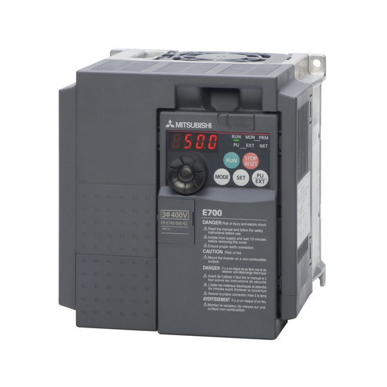
Inverter Type Symbol Voltage Class Symbol Type number E720S Single-phase 230V 3-digit display E740 Three-phase 400V class I001905E Fig. 1-1: Inverter Type FR-E700 EC FR-E700 EC 1 - 1... -
Page 20: Description Of The Case
Description of the Case Product Checking and Part Identification Description of the Case Operation panel Cooling fan (refer to section 4.3) (refer to section 8.1.7) PU connector (siehe Abschn. 3.5) Voltage/current input switch USB connector (refer to section 3.4) (mini-B connector) (refer to section 3.6) Connector for plug- in option connection... -
Page 21: Accessory
Tab. 1-1: Fan cover fixing screws NOTES The fan cover fixing screws are not delivered with models FR-E720S-008 to 030 and FR-E740-026 or less. For removal and reinstallation of the cooling fans, refer to section 8.1.7. FR-E700 EC 1 - 3... - Page 22 Description of the Case Product Checking and Part Identification 1 - 4...
-
Page 23: Installation
Example: FR-E740-095 I002050E Fig. 2-1: Removal of the front cover Reinstallation To reinstall, match the cover to the inverter front and install it straight. Example: FR-E740-095 I001908E Fig. 2-2: Reinstallation of the front cover FR-E700 EC 2 - 1... -
Page 24: Fr-E740-230 And Fr-E740-300
Removal and reinstallation of the front cover Installation 2.1.2 FR-E740-230 and FR-E740-300 Removal Loosen the installation screws of the front cover 1. Remove the front cover 1 by pulling it toward you in the direction of arrow. Remove the front cover 2 by pulling it toward you in the direction of arrow (refer to the figure be- low). - Page 25 The same serial number is printed on the capacity plate of the front cover and the rating plate of the inverter. Before reinstalling the front cover, check the serial numbers to ensure that the cover removed is reinstalled to the inverter from where it was removed. FR-E700 EC 2 - 3...
-
Page 26: Removal And Reinstallation Of The Wiring Cover
Removal and reinstallation of the wiring cover Installation Removal and reinstallation of the wiring cover The cover can be removed easily by pulling it toward you. To reinstall, fit the cover to the inverter along the guides. FR-E720S-050 to 110 FR-E720S-008 to 030 FR-E740-016 to 095 Guides... -
Page 27: Mounting
When encasing multiple inverters, install them in parallel as a cooling measure. Leave enough clearances around the inverter (refer to page 2-11). Fig. 2-7: Good heat dissipation is achieved through the vertical alignment of the frequency inverter, the side-by-side mounting and maintenance of minimum clearances. I001911E FR-E700 EC 2 - 5... - Page 28 Mounting Installation The inverter consists of precision mechanical and electronic parts. Never install or handle it in any of the following conditions as doing so could cause an operation fault or failure. High temperature, Direct sunlight Vibration (≥ 5,9 m/s²) Horizontal placement high humidity Transportation by holding...
-
Page 29: Enclosure Design
Tab. 2-1: Environmental standard specifications of inverter Temperature The permissible ambient temperature of the inverter FR-E700 is between −10 and +50°C. Al- ways operate the inverter within this temperature range. Operation outside this range will con- siderably shorten the service lives of the semiconductors, parts, capacitors and others. Take the following measures so that the ambient temperature of the inverter falls within the specified range. - Page 30 Enclosure design Installation Humidity Normally operate the inverter within the 45 to 90% range of the ambient humidity. Too high hu- midity will pose problems of reduced insulation and metal corrosion. On the other hand, too low humidity may produce a spatial electrical breakdown. The insulation distance specified in JEM1103 "Control Equipment Insulator"...
- Page 31 Especially when impact is imposed repeatedly, caution must be taken as the part pins are likely to break. ● Countermeasures – Provide the enclosure with rubber vibration isolators. – Strengthen the structure to prevent the enclosure from resonance. – Install the enclosure away from sources of vibration. FR-E700 EC 2 - 9...
- Page 32 Enclosure design Installation Cooling system types for inverter enclosure From the enclosure that contains the inverter, the heat of the inverter and other equipment (transformers, lamps, resistors, etc.) and the incoming heat such as direct sunlight must be dis- sipated to keep the in-enclosure temperature lower than the permissible temperatures of the in- enclosure equipment including the inverter.
-
Page 33: Inverter Placement
Mount the inverter on a wall as specified. Do not mount it horizontally or any other way. Above the inverter Heat is blown up from inside the inverter by the small fan built in the unit. Any equipment placed above the inverter should be heat resistant. FR-E700 EC 2 - 11... - Page 34 Enclosure design Installation Arrangement of multiple inverters When multiple inverters are placed in the same enclosure, generally arrange them horizontally as shown in the figure (a). When it is inevitable to arrange them vertically to minimize space, take such measures as to provide guides since heat from the bottom inverters can increase the tem- peratures in the top inverters, causing inverter failures.
-
Page 35: Wiring
Moulded case circuit breaker formed from (MCCB) or earth leakage circuit FR-PU07. Inverter (FR-E700 EC) breaker (ELB), fuse The life of the inverter is influenced by ambient tempera- The breaker ust be selected carefully ture. The ambient temperature should be as low as pos- since an in-rush current flows in the sible within the permissible range. - Page 36 Inverter and peripheral devices Wiring NOTES Do not install a power factor correction capacitor or surge suppressor on the inverter output side. This will cause the inverter to trip or the capacitor and surge suppressor to be dam- aged. If any of the above devices are connected, immediately remove them. Electromagnetic Compatibility Operation of the frequency inverter can cause electromagnetic interference in the input and output that can be propagated by cable (via the power input lines), by wireless radiation to...
-
Page 37: Peripheral Devices
When the breaker on the inverter primary side trips, check for the wiring fault (short circuit), damage to internal parts of the inverter, etc. Identify the cause of the trip, then remove the cause and power on the breaker. FR-E700 EC 3 - 3... -
Page 38: Terminal Connection Diagramm
Terminal connection diagramm Wiring Terminal connection diagramm Source Logic *1 DC reactor Main circuit terminal When connecting a DC reactor, remove the jumper across P1 and +. Control circuit terminal Brake unit *6 A brake transistor is not built-in to the (Option) MCCB FR-E720S-008 and 015. - Page 39 Wire offcuts can cause an alarm, failure or malfunction. Always keep the inverter clean. When drilling mounting holes in an enclosure etc., take care not to allow chips and other for- eign matter to enter the inverter. The output of the single-phase power input specification is three-phase 230V. FR-E700 EC 3 - 5...
-
Page 40: Main Circuit Connection
Main circuit connection Wiring Main circuit connection 3.3.1 Specification of main circuit terminal Terminal Name Description R/L1, AC power input Connect to the commercial power supply. S/L2, Keep these terminals open when using the high power factor converter T/L3 (FR-HC) or power regeneration common converter (FR-CV). U, V, W Inverter output Voltage ouput of the inverter... -
Page 41: Terminal Layout And Wiring
Power supply Motor Power supply I002035E I002034E FR-E740-230 and 300 Screw size (230: M4, 300: M5) Jumper — Screw size (230: M4, 300: M5) L1L2 L3 Motor Power supply I002058E Tab. 3-4: Terminal layout and wiring FR-E700 EC 3 - 7... - Page 42 Main circuit connection Wiring CAUTION: ● The power supply cables must be connected to R/L1, S/L2, T/L3. Never connect the power cable to the U, V, W of the inverter. Doing so will damage the inverter. (Phase sequence needs not to be matched.) ●...
- Page 43 Line voltage drop [V] ------------------------------------------------------------------------------------------------------------------------------------------------------------------------ - 1000 Use a larger diameter cable when the wiring distance is long or when it is desired to decrease the voltage drop (torque reduction) in the low speed range. FR-E700 EC 3 - 9...
- Page 44 Main circuit connection Wiring CAUTION: ● Tighten the terminal screw to the specified torque. A screw that has been tighten too loosely can cause a short circuit or malfunction. A screw that has been tighten too tightly can cause a short circuit or malfunction due to the unit breakage. ●...
- Page 45 Inverter Other Inverter Other Inverter Other equipment equipment equipment (I) Independent earthing (II)Common earthing (III) Common earthing (best solution) (good solution) (not allowed) I001016E Fig. 3-4: Earthing the drive FR-E700 EC 3 - 11...
- Page 46 Main circuit connection Wiring Total wiring length The maximum possible length of the motor cables depends on the capacity of the inverter and the selected carrier frequency. The lengths in the following table are for unshielded cables. When shielded cables are use di- vide the values listed in the table by 2.
- Page 47 Refer to section 6.15.1 for details of Pr. 72 "PWM frequency selection". When using the automatic restart after instantaneous power failure function with wiring length exceeding than 100m, select without frequency search (Pr. 162 = "1, 11"). FR-E700 EC 3 - 13...
-
Page 48: Control Circuit Specifications
Control circuit specifications Wiring Control circuit specifications The functions of the terminals highlighted in grey can be adjusted with parameters 178 – 184 "In- put terminal function assignment" (refer to section 6.10). The listed settings show the default configuration as shipped, which you can restore by resetting to the factory defaults. Input signals Rated Terminal... - Page 49 Applying a voltage with voltage/current input switch in "I" position (current input is selected) or a current with switch in"V" position (voltage input is selected) could cause component damage of the inverter or analog circuit of output devices. Refer to section 6.16 for details. FR-E700 EC 3 - 15...
- Page 50 Control circuit specifications Wiring Output signals Rated Terminal Name Description Refer to Specifications The alarm is output via relay contacts. The block diagram shows the normal operation and Contact voltage free status. If the protective function is capacity: activated, the relay picks up. Relay output 230V AC/0.3A A, B, C...
-
Page 51: Control Circuit Terminals
Edge thickness: 0,4mm × 2,5mm Tab. 3-12: Connection to the terminals CAUTION: Undertightening can cause cable disconnection or malfunction. Overtightening can cause a short circuit or malfunction due to damage to the screw or unit. FR-E700 EC 3 - 17... - Page 52 Control circuit specifications Wiring Common terminals of the control circuits PC, 5, SE Terminals PC, 5, and SE are all common terminals (0V) for I/O signals and are isolated from each other. Avoid connecting the terminal PC and 5 and the terminal SE and 5. Terminal PC is a common terminal for the contact input terminals (STF, STR, RH, RM, RL, MRS and RES).
-
Page 53: Wiring Instructions
● The wiring length should be 30m maximum. ● Do not short terminal PC and SD. Inverter may be damaged. FR-E700 EC 3 - 19... -
Page 54: Changing The Control Logic
3.4.3 Changing the control logic FR-E700 frequency inverters offer the possibility of choosing between two types of control logic. Depending on the direction of the flowing current, one distinguishes between: ● In sink logic, a signal switches on when a current flows from the corresponding signal input terminal. - Page 55 The capacity plate is placed on the front cover and the rating plate is on the inverter. Since these plates have the same serial numbers, always reinstall the removed cover onto the ori- ginal inverter. FR-E700 EC 3 - 21...
- Page 56 Control circuit specifications Wiring Using an external power supply ● Sink logic type Use terminal PC as a common terminal to prevent a malfunction caused by undesirable current. (Do not connect terminal SD of the inverter with terminal 0V of the external power supply.
-
Page 57: Pu Connector
FR-PU07/FR-PA07 along the guide until the tabs snap into place. Overall wiring length when the parameter unit is connected: max. 20m. PU connector Cable FR-CB (option) FR-PA07 FR-PU07 II002059E Fig. 3-15: Connecting the parameter unit FR-PU07/FR-PA07 using a connection cable FR-E700 EC 3 - 23... -
Page 58: Rs485 Communication
PU connector Wiring 3.5.2 RS485 communication When the PU connector is connected with a personal, FA or other computer by a communication cable, a user program can run and monitor the inverter or read and write to parameters. The protocol can be selected from Mitsubishi inverter and Modbus RTU. For detailed informa- tion refer to section 6.19. -
Page 59: Usb Connector
USB mini B connector (receptacle mini B type) Power supply Self-power supply Tab. 3-13: USB connector specifications USB connector USB cable Pull the cover in the direction Then turn it upward. of the arrow. I001921E Fig. 3-16: Connection to the USB connector FR-E700 EC 3 - 25... -
Page 60: Connection Of Stand-Alone Option Units
Connection of stand-alone option units Wiring Connection of stand-alone option units The inverter accepts a variety of stand-alone option units as required. CAUTION: Incorrect connection will cause inverter damage or accident. Connect and operate the option unit carefully in accordance with the corresponding option unit manual. 3.7.1 Magnetic contactors (MC) Inverter input side magnetic contactor (MC) - Page 61 When the magnetic contactor is turned on while the inverter is operating, overcurrent protection of the inverter and such will activate. When an MC is provided for switch- ing to the commercial power supply, for example, switch it on/off after the inverter and motor have stopped. FR-E700 EC 3 - 27...
-
Page 62: Connection Of A Dedicated External Brake Resistor Fr-Abr And Mrs (Fr-E720S-030 Or More, Fr-E740-016 Or More)
Connection of stand-alone option units Wiring 3.7.2 Connection of a dedicated external brake resistor FR-ABR and MRS (FR-E720S-030 or more, FR-E740-016 or more) Install a dedicated brake resistor (FR-ABR) outside when the motor is made to run by the load, quick deceleration is required, etc. - Page 63 Terminal PR I001923E Brake resistor FR-E740-120 to 300 Fig. 3-20: Jumper Connection of a brake resistor to the terminals + and PR for the inverters FR-E740-120 and FR-E740-300 Terminal + Terminal PR Brake resistor I001924E FR-E700 EC 3 - 29...
- Page 64 Connection of stand-alone option units Wiring It is recommended to configure a sequence, which shuts off power in the input side of the in- verter by the external thermal relay as shown below, to prevent overheat and burnout of the high duty brake resistor (FR-ABR) in case the regenerative brake transistor is damaged.
- Page 65 ● Brake resistor can not be used with the brake unit (FR-BU2), high power factor converter (FR-HC), power supply regeneration converter (FR-CV), etc. ● Do not connect a resistor directly to the DC terminals + and –. This could cause a fire. FR-E700 EC 3 - 31...
-
Page 66: Connection Of A Brake Unit Fr-Bu2
Connection of stand-alone option units Wiring 3.7.3 Connection of a brake unit FR-BU2 When connecting a brake unit to improve the brake capability at deceleration, make connection as shown below. Connection example with the GRZG type discharging resistor Inverter Motor 3-phase AC power supply ≤... - Page 67 ● Do not remove a jumper across terminal + and P1 except when connecting a DC reactor. NOTE Set "1" in Pr. 0 "Brake mode selection" of the FR-BU2 to use GRZG type discharging resis- tor. FR-E700 EC 3 - 33...
- Page 68 Connection of stand-alone option units Wiring Connection example with the FR-BR(-H) type resistor Inverter Motor 3-phase AC power supply ≤ 5m 002045E Fig. 3-24: Connection with the brake unit FR-BU2 If the control contacts are only specified for 230V control power you must install a transformer when using a 400V power supply.
-
Page 69: Connection Of The High Power Factor Converter Fr-Hc
Use sink logic when the FR-HC is connected. The FR-HC cannot be connected when source logic (factory setting) is selected. Do not remove a jumper across terminal + and P1 except when connecting a DC reactor. FR-E700 EC 3 - 35... -
Page 70: Connection Of The Power Regeneration Common Converter Fr-Cv
Connection of stand-alone option units Wiring 3.7.5 Connection of the power regeneration common converter FR-CV When connecting the power regeneration common converter (FR-CV), make connection so that the inverter terminals (+, −) and the terminal symbols of the power regeneration common con- verter (FR-CV) are the same. -
Page 71: Connection Of The Power Improving Dc Reactor Fr-Hel
When connecting the FR-HEL, remove the jumper across terminals + and P1. NOTES The wiring length between the FR-HEL and inverter should be 5m maximum and minimized. Use the same wire size as that of the power supply wire (R/L1, S/L2, T/L3). (Refer to page 3-9.) FR-E700 EC 3 - 37... -
Page 72: Electromagnetic Compatibility (Emc)
When the wiring length is long (50m or more) for the 400V class small-capacity model (FR-E700-170 or less), the external thermal relay is likely to operate unnecessarily because the ratio of the leakage current to the rated motor current increases. - Page 73 The earth leakage breaker must be either a Mitsubishi earth leakage breaker (ELB, for har- monics and surges) or an ELB with breaker designed for harmonic and surge suppression that is approved for use with frequency inverters. FR-E700 EC 3 - 39...
- Page 74 Electromagnetic compatibility (EMC) Wiring Note on selecting a suitable power supply ELCB If you install a Mitsubishi frequency inverter with a 3-phase power supply in locations where an earth leakage contact breaker is required by the VDE you must install a universal-current sen- sitive ELCB conforming to the specifications laid down in VDE 0160 / EN 50178 (ELCB Type B).
- Page 75 NV-2F earth leakage relay (except NV-ZHA), NV with AA neutral wire open-phase pro- tection. The other models are designed for harmonic and surge suppression: NV-C/NV-S/MN series, NV30-FA, NV50-FA, BV-C2, earth leakage alarm breaker (NF-Z), NV-ZHA, NV-H FR-E700 EC 3 - 41...
-
Page 76: Inverter-Generated Noises And Their Reduction Techniques
Electromagnetic compatibility (EMC) Wiring 3.8.2 Inverter-generated noises and their reduction techniques Some noises enter the inverter to malfunction it and others are radiated by the inverter to mal- function peripheral devices. Though the inverter is designed to be insusceptible to noises, it han- dles low-level signals, so it requires the following basic techniques. - Page 77 Electrical path ... Path through power supply propagated noise cable Ground wire by ... Path leakage current I001048E Fig. 3-31: Noise propagation Telephone Sensor power supply Inverter Receiver Instrument Sensor Motor I001049E Fig. 3-32: Noise paths FR-E700 EC 3 - 43...
- Page 78 Electromagnetic compatibility (EMC) Wiring Noise Measures Propagation Path When devices that handle low-level signals and are liable to malfunction due to noises, e.g. instruments, receivers and sensors, are contained in the enclosure that contains the inverter or when their signal cables are run near the inverter, the devices may be malfunctioned by air- propagated noises.
-
Page 79: Power Supply Harmonics
For power factor improvement, install a reactor on the inverter input side or in the DC circuit. FR-E700 EC 3 - 45... -
Page 80: Inverter-Driven 400V Class Motor
Electromagnetic compatibility (EMC) Wiring 3.8.4 Inverter-driven 400V class motor In the PWM type inverter, a surge voltage attributable to wiring constants is generated at the mo- tor terminals. Especially for a 400V class motor, the surge voltage may deteriorate the insula- tion. -
Page 81: Operation
Operation Precautions for use of the inverter The FR-E700 series is a highly reliable product, but incorrect peripheral circuit making or op- eration/handling method may shorten the product life or damage the product. Before starting operation, always recheck the following items. - Page 82 Precautions for use of the inverter Operation ● Do not use the inverter input side magnetic contactor to start/stop the inverter. Always use the start signal (ON/OFF of STF and STR signals) to start/stop the inverter. ● Across + and PR terminals, connect only an external regenerative brake discharging resistor. Do not connect a mechanical brake.
-
Page 83: Failsafe Of The System Which Uses The Inverter
In addition, negative logic can be set (on when the inverter is normal, off when the fault oc- curs). Inverter fault occurrence (trip) Time ON (no Alarm) (when output at NC contact) Reset processing Reset ON (about 1s) I001877E Fig. 4-2: Kontakt B-C opens when a fault occurs (initial setting) FR-E700 EC 4 - 3... - Page 84 Precautions for use of the inverter Operation Checking the inverter operating status by the inverter operation ready completion signal Operation ready signal (RY signal) is output when the inverter power is on and the inverter be- comes operative. Check if the RY signal is output after powering on the inverter. Checking the inverter operating status by the start signal input to the inverter and inverter running signal The inverter running signal (RUN signal) is output when the inverter is running (RUN signal is as-...
- Page 85 Check if there is no gap between the actual speed and commanded speed by comparing the inverter speed command and detected speed of the speed detector. Controller System failure Sensor Inverter (speed, temperature, air volume, etc.) To the alarm detection sensor I001879E Fig. 4-4: Backup method outside the inverter FR-E700 EC 4 - 5...
-
Page 86: Drive The Motor
Drive the motor Operation Drive the motor The inverter needs frequency command and start command. Refer to the flow chart below to perform setting. Step of operation Installation/mounting Frequency command Frequency [Hz] Wiring of the power supply and motor Output frequency Time [s] System examination... -
Page 87: Operation Panel
(Refer to section 6.18.3). I001732E Fig. 4-6: Operation panel of the FR-E700 The number of digits displayed on the operation panel is four. Only the upper four digits of values can be displayed and set. If the values to be displayed have five digits or more including decimal places, the fifth or later numerals can not be displayed nor set. - Page 88 Operation panel Operation Function Description Used to change the frequency setting and parameter values. Press to display the following. Digital dial Displays the set frequency in the monitor mode Currently set value is displayed during calibration Displays the order in the faults history mode RUN command for forward/reverse rotation.
-
Page 89: Basic Operation (Factory Setting)
The operation for displaying the alarm history is explained in section 7.5. The past eight alams can be displayed. (The latest alarm is ended by „.“.) When no alarm history exists, is displayed. I001736E Fig. 4-7: Overview of the basic functions of the operation panel FR-E700 EC 4 - 9... -
Page 90: Easy Operation Mode Setting (Easy Setting Mode)
Operation panel Operation 4.3.3 Easy operation mode setting (easy setting mode) A frequency inverter can be controlled alone via the control unit, through external signals (switch, SPC outputs, external setpoint sources, etc.) or through a combination of external sig- nals and inputs to the control unit. The choice of operation mode is done by setting parameter 79. - Page 91 – Setting can not be made during operation. Turn the start switch (RUN, STF or STR) off. ● The priorities of the frequency commands when Pr. 79 = "3" are "Multi-speed operation (RL/ RM/RH/REX) > PID control (X14) > terminal 4 analog input (AU) > digital input from the operation panel". FR-E700 EC 4 - 11...
-
Page 92: Operation Lock
Operation panel Operation 4.3.4 Operation lock Operation using the digital dial and key of the operation panel can be made invalid to prevent pa- rameter change and unexpected start and stop. Operation lock ● Set "10" or "11" in Pr. 161, then press the MODE key for 2s to make the digital dial key operation invalid. - Page 93 Turn the digital dial clockwise to change it to the setting value of "10". Press the SET key to set. Flicker ... Parameter setting complete! Press the MODE key for 2s to show the key lock mode. I001739E Fig. 4-9: Operation lock FR-E700 EC 4 - 13...
-
Page 94: Monitoring Of Output Current And Output Voltage
Operation panel Operation 4.3.5 Monitoring of output current and output voltage Monitor display of output frequency, output current and output voltage can be changed by push- ing the SET key during monitoring mode. Operation Display Press the MODE key during operation to choose the output frequency monitor. -
Page 95: Change The Parameter Setting Value
● "ER1" to "ER4" is displayed ... Why? – The error indication means: ER1: Write disable error ER2: Write error during operation ER3: Calibration error Er4: Mode designation error For details refer to section 7.1. FR-E700 EC 4 - 15... -
Page 96: Parameter Clear/All Parameter Clear
Operation panel Operation 4.3.9 Parameter clear/All Parameter clear ● Set "1" in Pr.CL "Parameter clear" or ALLC "all parameter clear" to initialize all parameters. (Parameters are not cleared when "1" is set in Pr. 77 "Parameter write selection".) ● Parameter clear returns all parameters except calibration parameters C1 (Pr. 901) to C7 (Pr. -
Page 97: Initial Value Change List
Pr. 160 is displayed independently of whether the setting value is changed or not. When parameter setting is changed after creating the initial value change list, the setting will be reflected to the initial value change list next time. FR-E700 EC 4 - 17... - Page 98 Operation panel Operation Operation Display Screen at powering on The monitor display appears. PU indication is lit. Press the PU/EXT key to choose the PU operation mode. PRM indication is lit. Press the MODE key to choose the parameter setting mode. The parameter number read previously appears..
-
Page 99: Basic Settings
3 %: FR-E740-120 and 170 2 %: FR-E740-230 and 300 Initial values differ according to the inverter capacity: 5 s: FR-E720S-110 or less, FR-D740-110 or less 10 s: FR-E740-120 and 170 15 s: FR-E740-2300 and 300 FR-E700 EC 5 - 1... -
Page 100: Overheat Protection Of The Motor By The Inverter
Simple mode parameter list Basic settings 5.1.1 Overheat protection of the motor by the inverter Set this parameter when using a motor other than the Mitsubishi standard motor (SF-JR) and Mitsubishi constant torque motor (SF-HRCA). Set the rated motor current in Pr. 9 "Electronic thermal O/L relay"... - Page 101 A special motor cannot be protected by the electronic thermal relay function. Use an exter- nal thermal relay. Electronic thermal relay does not work when 5% or less of inverter rated current is set to electronic thermal relay setting. FR-E700 EC 5 - 3...
-
Page 102: When The Rated Motor Frequency Is 60Hz (Pr. 3)
Simple mode parameter list Basic settings 5.1.2 When the rated motor frequency is 60Hz (Pr. 3) First, check the motor rating plate. If a frequency given on the rating plate is "60Hz" only, always set Pr. 3 "Base frequency" to "60Hz". Leaving the base frequency unchanged from "50Hz" may make the voltage low and the torque insufficient. -
Page 103: Increase The Starting Torque (Pr. 0)
(The guideline is for about 10% change at the greatest.) Fig. 5-3: Relation between output frequency and output voltage Setting range Pr. 0, Pr. 46 Base frequency Output frequency [Hz] I001098E FR-E700 EC 5 - 5... - Page 104 Simple mode parameter list Basic settings Operation Display Screen at powering on The monitor display appears. PU indication is lit. Press the PU/EXT key to choose the PU operation mode. PRM indication is lit. Press the MODE key to choose the parameter setting mode.
-
Page 105: Limit The Maximum And Minimum Output Frequency (Pr. 1, Pr. 2)
(Set "50"Hz to Pr. 1 "Maximum frequency".) Fig. 5-5: Minimum and maximum output frequency Output frequency [Hz] Clamped at the maximum frequency Pr. 1 Pr. 18 Frequency setting Pr. 2 5, 10V (4mA) (20mA) Clamped at the minimum frequency I001100E FR-E700 EC 5 - 7... - Page 106 Simple mode parameter list Basic settings Operation Display Screen at powering on The monitor display appears. PU indication is lit. Press the PU/EXT key to choose the PU operation mode. PRM indication is lit. Press the MODE key to choose the parameter setting mode.
-
Page 107: Change The Acceleration/Deceleration Time (Pr. 7, Pr. 8)
Too short acceleration/deceleration times may lead to an inverter shutoff with error message (E.THT, E.THM, E.OCT, E.OVT ...). Example Change the Pr. 7 "Acceleration time" setting from "5s" to "10s". Fig. 5-7: Acceleration/deceleration time Pr. 20 Pr. 7 Pr. 8 I000006C FR-E700 EC 5 - 9... - Page 108 Simple mode parameter list Basic settings Operation Display Screen at powering on The monitor display appears. PU indication is lit. Press the PU/EXT key to choose the PU operation mode. PU indication is lit. Press the MODE key to choose the parameter setting mode.
-
Page 109: Operation Mode (Pr. 79)
Pr. 184, refer to section 6.10.1. When the X12 signal is not assigned, function of the MRS signal switches from MRS (output stop) to PU operation interlock signal. NOTE Setting value "1" to "4" can be changed in the easy operation mode. (Refer to section 4.3.3.) FR-E700 EC 5 - 11... -
Page 110: Large Starting Torque And Low Speed Torque Are Necessary (Advance Magnetic Flux Control, General-Purpose Magnetic Flux Vector Control) (Pr. 71, Pr. 80, Pr. 81, Pr. 800)
Simple mode parameter list Basic settings 5.1.7 Large starting torque and low speed torque are necessary (Advance magnetic flux control, general-purpose magnetic flux vector control) (Pr. 71, Pr. 80, Pr. 81, Pr. 800) AD MFVC AD MFVC AD MFVC GP MFVC GP MFVC GP MFVC Advanced magnetic flux vector control can be selected by setting the capacity, poles and type... - Page 111 Uneven rotation slightly increases as compared to the V/F control. (It is not suitable for machines such as grinding machine and wrapping machine which requires less uneven rotation at low speed.) Use Pr. 89 to adjust the motor speed fluctuation at load fluctuation. (Refer to section 6-36.) FR-E700 EC 5 - 13...
- Page 112 Simple mode parameter list Basic settings Selection method of general-purpose magnetic flux vector control Perform secure wiring. (Refer to section 3.2.) Set the motor. (Pr. 71) (Refer to page 5-12.) Motor Pr. 71 Remarks SF-JR Initial value Standard motor, high efficiency SF-HR —...
-
Page 113: To Exhibit The Best Performance Of The Motor Performance (Offline Auto Tuning) (Pr. 9, Pr. 71, Pr. 83, Pr. 84, Pr. 96)
Reading/writing/copy of motor constants tuned by offline auto tuning are enabled. The offline auto tuning status can be monitored with the operation panel and PU (FR-PU04/ FR-PU07). FR-E700 EC 5 - 15... - Page 114 Simple mode parameter list Basic settings Before performing offline auto tuning Check the following before performing offline auto tuning. ● Make sure advanced magnetic flux vector control or general-purpose magnetic flux vector control (Pr. 80, Pr. 81) is selected (refer to section 5.1.7). (Tuning can be performed even under V/f control selected by turning on X18.) ●...
- Page 115 When executing offline auto tuning, input the run command after switching on the main cir- cuit power (R/L1, S/L2, T/L3) of the inverter. Do not perform ON/OFF switching of the second function selection signal (RT) during execu- tion of offline auto tuning. Auto tuning is not excecuted properly. FR-E700 EC 5 - 17...
- Page 116 Simple mode parameter list Basic settings Monitor display during auto tuning Monitor is displayed on the operation panel and parameter unit (FR-PU04/FR-PU07) during tun- ing as below. Parameter Unit Operation Panel Indication (FR-PU04/FR-PU07) Display Parameter 96 Setting READ:List READ:List STOP STOP Tuning in progress...
- Page 117 As the motor may run slightly during offline auto tuning, fix the motor securely with a mechanical brake or make sure that there will be no problem in safety if the motor runs. Note that if the motor runs slightly, tuning performance is unaffected. FR-E700 EC 5 - 19...
-
Page 118: Pu Operation Mode
PU operation mode Basic settings PU operation mode From where is the frequency command given? ● Operation at the frequency set in the frequency setting mode of the operation panel. (Refer to section 5.2.1.) ● Operation using the digital dial as the volume. (Refer to section 5.2.2.) ●... -
Page 119: Set The Set Frequency To Operate
PU/EXT key to change to the PU operation mode.) ● Operation does not change to the PU operation mode. – Check that "0" (initial value) is set in Pr. 79 Operation mode selection. – Check that the start command is not on. FR-E700 EC 5 - 21... - Page 120 PU operation mode Basic settings Change the acceleration time using Pr. 7 (refer to section 5.1.5) and the deceleration time using Pr. 8 (refer to section 5.1.5). The maximum output frequency is set in Pr. 1. (Refer to section 5.1.4.) NOTES Press the digital dial to show the set frequency.
-
Page 121: Use The Digital Dial Like A Potentiometer To Perform Operation
Independently of whether the inverter is running or at a stop, the frequency can be set by merely turning the digital dial. Use Pr. 295 "Magnitude of frequency change setting" to change the frequency setting incre- ments of the digital dial. FR-E700 EC 5 - 23... -
Page 122: Use Switches To Give The Frequency Command (Multi-Speed Setting)
Use switches to give the frequency command (multi-speed setting) In frequency inverters of the FR-E700 series up to 15 frequency setpoints (and thus rpms and speeds) can be selected via the RH, RM, RL and REX terminals. Manually activated switches or relay outputs of a programmble logic controller (PLC), for example, can be used to select a frequency. - Page 123 – Check for the Pr. 79 setting once again. (Pr. 79 must be set to "4".) (Refer to section 5.1.6.) NOTE Refer to section 5.3.2 to change the running frequency at each terminal in Pr. 4 "Multi-speed setting (highspeed)", Pr. 5 "Multi-speed setting (middle speed)", and Pr. 6 "Multi-speed set- ting (low speed)". FR-E700 EC 5 - 25...
-
Page 124: Perform Frequency Setting By Analog Voltage Input
PU operation mode Basic settings 5.2.4 Perform frequency setting by analog voltage input In this type of setpoint selection a potentiometer is connected to the frequency inverter. The po- tentiometer is supplied with a voltage of 5V through terminal 10 of the frequency inverter. Inverter Motor Power supply... - Page 125 Pr. 125 "Terminal 2 frequency setting gain frequency". (Refer to section 5.3.4.). Change the frequency (0Hz) of the minimum value of potentiometer (at 0V) by adjusting the frequency in calibration parameter C2 "Terminal 2 frequency setting bias frequency". (Refer to section 6.16.3.) FR-E700 EC 5 - 27...
-
Page 126: Perform Frequency Setting By Analog Current Input
PU operation mode Basic settings 5.2.5 Perform frequency setting by analog current input An external current source is connection to the frequency inverter for setpoint default setting. Inverter Power supply Motor AU signal Current signal source (0/4–20mA DC) I001773E Fig. 5-19: Frequency setting by analog current input ●... - Page 127 Pr. 126 "Terminal 4 frequency setting gain frequency". (Refer to section 5.3.6). Change the frequency (0Hz) at the minimum value of potentiometer (at 4mA) by adjusting the frequency in calibration parameter C5 "Terminal 4 frequency setting bias frequency". (Refer to section 6.16.3.) FR-E700 EC 5 - 29...
-
Page 128: External Operation
External operation Basic settings External operation From where is the frequency command given? ● Operation at the frequency set in the frequency setting mode of the operation panel. (Refer to section 5.3.1.) ● Give a frequency command by switch (multi-speed setting). (Refer to section 5.3.2). ●... - Page 129 (Refer to section 5.3.2.) Possible faults: ● Pressing th STOP/RESET key of the operation panel changed the display – Turn the start switch (STF or STR) off. – The display can be reset by PU/EXT. FR-E700 EC 5 - 31...
-
Page 130: Use Switches To Give A Start Command And A Frequency Command (Multi-Speed Setting) (Pr. 4 To Pr. 6)
External operation Basic settings 5.3.2 Use switches to give a start command and a frequency command (multi- speed setting) (Pr. 4 to Pr. 6) ● Start command by terminal STF (STR)-PC. ● Frequency command by terminal RH, RM, RL and STR-PC. ●... - Page 131 Forward rotation Stop Reverse rotation Turn the start switch (STF or STR) off. The motor stops according to Pr. 8 Stop "Deceleration time". I001778E Fig. 5-25: Operate the inverter by using external signals FR-E700 EC 5 - 33...
- Page 132 External operation Basic settings Possible faults: ● The EXT lamp is not lit even when the PU/EXT key is pressed. – Switchover of the operation mode with is valid when Pr. 79 = 0 (initial value). ● 50Hz, 30Hz and 10Hz are not output from RH, RM and RL respectively when they are turned on. –...
-
Page 133: Perform Frequency Setting By Analog Voltage Input
The frequency setting potentiometer is supplied with 5V of power from the inverter (terminal 10). Inverter Power supply Motor Forward rotation start Reverse rotation start Frequency setting potentiometer (1kΩ/2W) I001090E Fig. 5-26: Frequency setting by analog voltage input FR-E700 EC 5 - 35... - Page 134 External operation Basic settings Operation Display Power on → operation mode check For the initial setting, the inverter operates in the external operation mode "EXT" when powering on. Check that the operation command indication is "EXT". If not displayed, press the PU/EXT key to change to the external "EXT"...
- Page 135 – Check that the EXT lamp is lit. The external operation mode is valid when Pr. 79 = 0 (initial value). Use the PU/EXT key to change into the external operation mode. – Check that wiring is correct. Check once again. FR-E700 EC 5 - 37...
-
Page 136: Change The Frequency (40Hz) Of The Maximum Value Of Potentiometer (At 5V)
External operation Basic settings 5.3.4 Change the frequency (40Hz) of the maximum value of potentiometer (at 5V) Example The frequency of the maximum analog voltage of the potentiometer (at 5V) has to be changed from the initial setting of 50Hz to 40 Hz. Set 40Hz in Pr. 125. Operation Display Turn the digital dial until P.125 (Pr. -
Page 137: Perform Frequency Setting By Analog Current Input
For the analog current input (0/4 to 20 mA) to become effective for setpoint default setting, the AU signal on the AU terminal must be activated. This is done, for example, by means of a bridge as shown in Fig. 5-29. FR-E700 EC 5 - 39... - Page 138 External operation Basic settings Operation Display Power on → operation mode check For the initial setting, the inverter operates in the external operation mode "EXT" when powering on. Check that the operation command indication is "EXT". If not displayed, press the PU/EXT key to change to the external "EXT"...
-
Page 139: Change The Frequency (40Hz) Of The Maximum Value Of Potentiometer (At 20Ma)
(Refer to section 6.16.3 for the setting method of calibration parameter C7.) When performing a high speed operation at 120Hz or more, setting of Pr. 18 "High speed maximum frequency" is necessary. (Refer to section 6.4.1.) FR-E700 EC 5 - 41... - Page 140 External operation Basic settings 5 - 42...
-
Page 141: Parameter
Set the lower limit of the output ✔ ✔ ✔ Minimum frequency 0.01Hz 0–120Hz frequency 6-50 High speed maximum Set when performing operation at ✔ ✔ ✔ 0.01Hz 120Hz 120–400Hz frequency 120Hz or more Tab. 6-1: Parameter overview (1) FR-E700 EC 6 - 1... - Page 142 Parameter overview Parameter Para- Para- Para- Parameter meter meter meter copy clear clear Refer Func- Incre- Initial Setting Name Description tion ments value range page ✔: enabled —: disabled Set the frequency when the motor ✔ ✔ ✔ Base frequency 0.01Hz 50Hz 0–400Hz...
- Page 143 Made valid when the RT signal is 0–500A on. Set the rated motor current. 6-80 Second electronic ✔ ✔ ✔ 0.01A 9999 thermal O/L relay Second electronic thermal O/L 9999 relay invalid Tab. 6-1: Parameter overview (3) FR-E700 EC 6 - 3...
- Page 144 Parameter overview Parameter Para- Para- Para- Parameter meter meter meter copy clear clear Refer Func- Incre- Initial Setting Name Description tion ments value range page ✔: enabled —: disabled DC injection brake Set the operation frequency of the ✔ ✔ ✔...
- Page 145 Set this parameter when a high Special regenerative ✔ ✔ ✔ 0.1% 0–30% duty brake resistor or power brake duty regeneration converter is used. Tab. 6-1: Parameter overview (5) FR-E700 EC 6 - 5...
- Page 146 Parameter overview Parameter Para- Para- Para- Parameter meter meter meter copy clear clear Refer Func- Incre- Initial Setting Name Description tion ments value range page ✔: enabled —: disabled 0–400Hz/ ✔ ✔ ✔ Frequency jump 1A 0.01Hz 9999 9999 0–400Hz/ ✔...
- Page 147 — — carrying-over times 65535h is displayed. Reading only The numbers of operation time Operating time monitor exceeded 65535h is dis- 0–65535 — — — carrying-over times played. Reading only Tab. 6-1: Parameter overview (7) FR-E700 EC 6 - 7...
- Page 148 Parameter overview Parameter Para- Para- Para- Parameter meter meter meter copy clear clear Refer Func- Incre- Initial Setting Name Description tion ments value range page ✔: enabled —: disabled Set the full-scale value to output Frequency monitoring ✔ ✔ ✔ 0.01Hz 50Hz 0–400Hz...
- Page 149 Acceleration/decelera- Calculates only acceleration time ✔ ✔ ✔ tion separate selection for the shortest acceleration/decel- eration mode. Calculates only deceleration time for the shortest acceleration/decel- eration mode Tab. 6-1: Parameter overview (9) FR-E700 EC 6 - 9...
- Page 150 Parameter overview Parameter Para- Para- Para- Parameter meter meter meter copy clear clear Refer Func- Incre- Initial Setting Name Description tion ments value range page ✔: enabled —: disabled ✔ ✔ ✔ Retry selection 0–5 An alarm for retry can be selected. No retry function Set the number of retries at alarm 1–10...
- Page 151 Thermal characteristics of a stand- ard motor Thermal characteristics of the Mit- ✔ ✔ ✔ Second applied motor 9999 subishi constant-torque motor Second motor is invalid (thermal 9999 characteristic of the first motor (Pr.71)) Tab. 6-1: Parameter overview (11) FR-E700 EC 6 - 11...
- Page 152 Parameter overview Parameter Para- Para- Para- Parameter meter meter meter copy clear clear Refer Func- Incre- Initial Setting Name Description tion ments value range page ✔: enabled —: disabled PWM carrier frequency can be PWM frequency changed. The setting displayed is ✔...
- Page 153 (all clear) is executed from RS-485 communication. (Refer to section 6.19 for RS-485 communication) Note that when using a three-phase power input specification model, Pr. 345 and Pr. 346 are set back to initial values. FR-E700 EC 6 - 13...
- Page 154 Parameter overview Parameter Para- Para- Para- Parameter meter meter meter copy clear clear Refer Func- Incre- Initial Setting Name Description tion ments value range page ✔: enabled —: disabled Tuning data (The value measured by offline auto tuning is automati- 0–500A * cally set.) Motor excitation cur-...
- Page 155 Pr. 71 setting. Use the Mitsubishi motor (SF-JR, 9999 SF-HRCA) constants Refer to Pr. 81 — – Refer to Pr. 82 to 84 Refer to Pr. 82 to 84 Tab. 6-1: Parameter overview (15) FR-E700 EC 6 - 15...
- Page 156 Parameter overview Parameter Para- Para- Para- Parameter meter meter meter copy clear clear Refer Func- Incre- Initial Setting Name Description tion ments value range page ✔: enabled —: disabled Set the inverter station numbers when two or more inverters are connected to one personal compu- PU communication 0–31...
- Page 157 (all clear) is executed from RS-485 communication. (Refer to section 6.19 for RS-485 communication) Note that when using a three-phase power input specification model, Pr. 345 and Pr. 346 are set back to initial values. FR-E700 EC 6 - 17...
- Page 158 Parameter overview Parameter Para- Para- Para- Parameter meter meter meter copy clear clear Refer Func- Incre- Initial Setting Name Description tion ments value range page ✔: enabled —: disabled Terminal 2 frequency Set the frequency of terminal 2 ✔ ✔ 0.01Hz 50Hz 0–400Hz...
- Page 159 (P) action. As ✔ ✔ ✔ PID differential time 0.01s 9999 the differential time increases, greater response is made to a deviation change. 9999 No differential control. Tab. 6-1: Parameter overview (19) FR-E700 EC 6 - 19...
- Page 160 Parameter overview Parameter Para- Para- Para- Parameter meter meter meter copy clear clear Refer Func- Incre- Initial Setting Name Description tion ments value range page ✔: enabled —: disabled Japanese English German French PU display language ✔ — — 6-306 selection Spanish Italian...
- Page 161 62: Inverter reset 64: PID forward/reverse action RES terminal function ✔ ✔ — switchover selection 65: NET/PU operation switchover 66: External/NET operation switchover 67: Command source switchover 9999: No function Tab. 6-1: Parameter overview (21) FR-E700 EC 6 - 21...
- Page 162 Parameter overview Parameter Para- Para- Para- Parameter meter meter meter copy clear clear Refer Func- Incre- Initial Setting Name Description tion ments value range page ✔: enabled —: disabled 0/100: Inverter running 1/101: Up to frequencych 0/1/3/4/7/8/ 3/103: Overload alarm 11–16/20/ 25/26/46/ 4/104: Output frequency...
- Page 163 Start signal 8888 STR signal: Forward/reverse When the signal start signal is turned off, the STF signal: motor decel- Forward rotation erates to stop. start 9999 STR signal: Reverse rotation start Tab. 6-1: Parameter overview (23) FR-E700 EC 6 - 23...
- Page 164 Parameter overview Parameter Para- Para- Para- Parameter meter meter meter copy clear clear Refer Func- Incre- Initial Setting Name Description tion ments value range page ✔: enabled —: disabled Without output phase failure protection Output phase failure ✔ ✔ ✔ protection selection With output phase failure protection...
- Page 165 6-291 Set the time constant of the pri- Droop filter time ✔ ✔ ✔ 0.01s 0.3s 0–1s mary delay filter applied to the constant torque current. Tab. 6-1: Parameter overview (25) FR-E700 EC 6 - 25...
- Page 166 Parameter overview Parameter Para- Para- Para- Parameter meter meter meter copy clear clear Refer Func- Incre- Initial Setting Name Description ments value range tion page ✔: enabled —: disabled — Refer to Pr. 61 Invalid Magnitude of fre- The setting increments when the ✔...
- Page 167 (all clear) is executed from RS-485 communication. (Refer to section 6.19 for RS-485 communication) Note that when using a three-phase power input specification model, Pr. 345 and Pr. 346 are set back to initial values. FR-E700 EC 6 - 27...
- Page 168 Parameter overview Parameter Para- Para- Para- Parameter meter meter meter copy clear clear Refer Func- Incre- Initial Setting Name Description ments value range tion page ✔: enabled —: disabled Set the time taken to average the ✔ ✔ ✔ Current average time 0.1s 0.1–1.0s current during start bit output...
- Page 169 Initial value change list Displays the parameters changed from the initial value. 4-17 Tab. 6-1: Parameter overview (29) NOTE The parameter number in parentheses is the one for use with the parameter unit (FR-PU04/ FR-PU07). FR-E700 EC 6 - 29...
-
Page 170: Control Mode
Control mode Parameter Control mode V/f control (initial setting), advanced magnetic flux vector control and general-purpose magnetic flux vector control are available with this inverter. V/f control It controls frequency and voltage so that the ratio of frequency (f) to voltage (V) is constant when changing frequency. -
Page 171: Change The Control Method (Pr. 80, Pr. 81, Pr. 800)
Tab. 6-2: Selection of control method Control method is V/f control regardless of the setting value of Pr. 800 when "9999" is set in Pr. 80 "Motor capacity" or Pr. 81 "Number of motor poles". FR-E700 EC 6 - 31... - Page 172 Control mode Parameter Control method switching by external terminals (X18 signal) ● Use the V/f switchover signal (X18) to change the control method (V/f control-advanced magnetic flux vector control (general-purpose magnetic flux vector control)) with external terminal. ● Turn the X18 signal on to change the currently selected control method (advanced magnetic flux vector control or general-purpose magnetic flux vector control) to V/f control.
- Page 173 Set the torque boost value 0–30% when the RT signal is on. Second torque 9999 boost Without second torque 9999 boost The above parameter can be set when Pr. 160 "User group read selection" = 0. FR-E700 EC 6 - 33...
- Page 174 Adjust the output torque (current) of the motor Parameter Starting torque adjustment On the assumption that Pr. 19 "Base frequency voltage" is 100%, set the output voltage at 0Hz in % to Pr. 0 (Pr. 46). Fig. 6-1: Relationship between output frequency and output voltage [ % ] Setting range Pr.
- Page 175 Pr. 0 setting changes to 2%. Changing the terminal assignment using Pr. 178 to Pr. 189 "Input terminal function selec- tion" may affect the other functions. Please make setting after confirming the function of each terminal. FR-E700 EC 6 - 35...
- Page 176 Adjust the output torque (current) of the motor Parameter 6.3.2 Advanced magnetic flux vector control (Pr. 71, Pr. 80, Pr. 81, Pr.89, Pr. 800) AD MFVC AD MFVC AD MFVC Advanced magnetic flux vector control can be selected by setting the capacity, poles and type of the motor used in Pr.
- Page 177 Uneven rotation slightly increases as compared to the V/f control. It is not suitable for machines such as grinding machine and wrapping machine which requires less uneven rotation at low speed. When a surge voltage suppression filter (FFR-DT) is connected between the inverter and motor, output torque may decrease. FR-E700 EC 6 - 37...
- Page 178 The motor speed fluctuation at load fluctuation can be adjusted using Pr. 89. (It is useful when the speed command does not match the motor speed after the FR-E500 series inverter is re- placed with the FR-E700 series inverter, etc.) Fig. 6-3:...
- Page 179 30m.) ● Permissible wiring length between inverter and motor differs according to the inverter capacity and setting value of Pr. 72 "PWM frequency selection" (carrier frequency). (Refer to page 3-12). FR-E700 EC 6 - 39...
- Page 180 Adjust the output torque (current) of the motor Parameter Selection method of general-purpose magnetic flux vector control Perform secure wiring. (Refer to section 3.2.) Set the motor. (Pr. 71) Motor Pr. 71 Remarks SF-JR Mitsubishi standard (initial value) motor SF-HR Mitsubishi high effi- ciency motor Others...
-
Page 181: Adjust The Output Torque (Current) Of The Motor
Set the Pr. 1 "Maximum frequency" value a little higher than the set frequency. Slip compensation is always valid when advanced magnetic flux vector control is selected, the Pr. 245 to Pr. 247 settings are invalid. FR-E700 EC 6 - 41... -
Page 182: Stall Prevention
Adjust the output torque (current) of the motor Parameter 6.3.5 Stall prevention operation (Pr. 22, Pr. 23, Pr. 48, Pr. 66, Pr. 156, Pr. 157, Pr. 277) This function monitors the output current and automatically changes the output frequency to prevent the inverter from coming to trip due to overcurrent, overvoltage, etc. - Page 183 When stall prevention operation is performed, the OL signal is output. Output current Pr. 22 Output frequency Constant speed Time I001120E Fig. 6-6: Stall prevention operation example NOTE If an overload status lasts long, an inverter trip (e.g. electronic thermal relay function "E.THM") may occur. FR-E700 EC 6 - 43...
- Page 184 Adjust the output torque (current) of the motor Parameter A machine protection and load limit by torque limit (Pr. 277) When Pr. 277 "Stall prevention current switchover" = 1, torque limit can be set. When output torque (torque current) exceeds the stall prevention operation level, the output fre- quency is controlled to limit the output torque.
- Page 185 (E.OLT) appears to trip the inverter output. Changing the terminal assignment using Pr. 190 to Pr. 192 "Output terminal function selec- tion" may affect the other functions. Make setting after confirming the function of each termi- nal. FR-E700 EC 6 - 45...
- Page 186 Adjust the output torque (current) of the motor Parameter Setting of stall prevention operation in high frequency range (Pr. 22, Pr. 23, Pr. 66) During high-speed operation above the rated motor frequency, acceleration may not be made because the motor current does not increase. If operation is performed in a high frequency range, the current at motor lockup becomes smaller than the rated output current of the inverter, and the protective function (OL) is not executed if the motor is at a stop.
- Page 187 Changing the terminal assignment using Pr. 178 to Pr. 184 "Input terminal function selec- tion" may affect the other functions. Make setting after confirming the function of each termi- nal. The RT signal acts as the second function selection signal and makes the other second functions valid. FR-E700 EC 6 - 47...
- Page 188 Adjust the output torque (current) of the motor Parameter Limit the stall prevention operation and fast-response current limit operation according to the operating status (Pr. 156) Refer to the following table and select whether fast-response current limit operation will be per- formed or not and the operation to be performed at OL signal output: Stall Prevention Operation Level OL Signal Output...
- Page 189 Stall prevention operation during acceleration may increase the acceleration time. Stall prevention operation performed during constant speed may cause sudden speed changes. Stall prevention operation during deceleration may increase the deceleration time, increasing the deceleration distance. FR-E700 EC 6 - 49...
-
Page 190: Limit The Output Frequency
Limit the output frequency Parameter Limit the output frequency Refer to Purpose Parameters that must be set Section Set upper limit and lower limit of output Maximum/minimum frequency Pr. 1, Pr. 2, 6.4.1 frequency Pr. 18 Perform operation by avoiding machine Frequency jump Pr. - Page 191 If the Pr. 2 setting is higher than the Pr. 13 "Starting frequency" value, note that the motor will run at the set frequency according to the acceleration time setting by merely switching the start signal on, without entry of the command frequency. FR-E700 EC 6 - 51...
-
Page 192: Avoid Mechanical Resonance Points (Frequency Jumps)
Limit the output frequency Parameter 6.4.2 Avoid mechanical resonance points (frequency jumps) (Pr. 31 to Pr. 36) When it is desired to avoid resonance attributable to the natural frequency of a mechanical sys- tem, these parameters allow resonant frequencies to be jumped. Refer to Name Initial Value... - Page 193 Pr.32 (1B) Pr.31 (1A) Pr.31 (1A) Pr.32 (1B) Set frequency Set frequency I00019aC Fig. 6-12: Selection of the jump point NOTE During acceleration/deceleration, the running frequency within the set area is valid. FR-E700 EC 6 - 53...
-
Page 194: Set V/F Pattern
Set V/f pattern Parameter Set V/f pattern Refer to Purpose Parameters that must be set Section Set motor ratings Base frequency, Base frequency voltage Pr. 3, Pr. 19, 6.5.1 Pr. 47 Select a V/f pattern according to Load pattern selection Pr. - Page 195 Changing the terminal assignment using Pr. 178 to Pr. 184 "Input terminal function selec- tion" may affect the other functions. Make setting after confirming the function of each termi- nal. Note that the output voltage of the inverter cannot exceed the power supply voltage. FR-E700 EC 6 - 55...
-
Page 196: Load Pattern Selection (Pr. 14)
Set V/f pattern Parameter 6.5.2 Load pattern selection (Pr. 14) You can select the optimum output characteristic (V/f characteristic) for the application and load characteristics. Initial Refer to Name Setting Range Description Parameters referred to Value Section For constant torque load Torque boost 6.3.1 Second torque... - Page 197 Changing the terminal assignment using Pr. 178 to Pr. 184 "Input terminal function selec- tion" may affect the other functions. Make setting after confirming the function of each termi- nal. FR-E700 EC 6 - 57...
-
Page 198: Frequency Setting By External Terminals
Frequency setting by external terminals Parameter Frequency setting by external terminals Refer to Purpose Parameters that must be set Section Make frequency setting by combina- Multi-speed operation Pr. 4–Pr. 6, 6.6.1 tion of terminals Pr. 24–Pr. 27 Pr. 232–Pr. 239 Perform jog operation Jog operatio Pr. - Page 199 "0 (RL)", "1 (RM)", "2 (RH)" in any of Pr. 178 to Pr. 184 "Input terminal function assig- nment", you can assign the signals to other terminals. For the terminal used for REX signal input, set "8" in any of Pr. 178 to Pr. 184 to assign the function. FR-E700 EC 6 - 59...
- Page 200 Frequency setting by external terminals Parameter Fig. 6-19: Connection example Forward rotation I001127E NOTES The priorities of the frequency commands by the external signals are "jog operation > multi- speed operation > terminal 4 analog input > terminal 2 analog input". (Refer to section 6.16 for the frequency command by analog input.) Valid in external operation mode or PU/external combined operation mode (Pr.
-
Page 201: Jog Operation (Pr. 15, Pr. 16)
Inverter Power Motor supply Forward rotation start Reverse rotation start Jog operation When assigning the jog signal to the terminal RH I001788E Fig. 6-20: Connection diagram for external jog operation FR-E700 EC 6 - 61... - Page 202 Frequency setting by external terminals Parameter Fig. 6-21: Jog operation signal timing chart frequency Forward rotation Pr. 20 Pr. 15 Pr. 16 Reverse rotation I001324C Operation Display Screen at powering on Confirm that the external operation mode is selected. (EXT indication is lit) If not displayed, press the PU/EXT key to change to the external operation mode If the operation mode still does not change, set Pr.
- Page 203 Turn the digital dial to set the value to "10.00" (10.00Hz). Press the SET key to set. Perform the operations in steps The motor rotates at 10Hz. Flicker ... Parameter setting complete! I001791E Fig. 6-24: JOG operation performed from PU FR-E700 EC 6 - 63...
- Page 204 Frequency setting by external terminals Parameter NOTES When Pr. 29 "Acceleration/deceleration pattern selection" = "1" (S-pattern acceleration/ deceleration A), the acceleration/deceleration time is the period of time required to reach Pr. 3 "Base frequency". The Pr. 15 setting should be equal to or higher than the Pr. 13 "Starting frequency setting". The JOG signal can be assigned to the input terminal using any of Pr.
-
Page 205: Remote Setting Function (Pr. 28)
Pr. 59 = 2, 3 Time Acceleration RH Deceleration RM Clear RL Forward rotation STF Power supply I001133E Fig. 6-26: Example of the remote setting function * External operation frequency (other than multi-speed) or PU running frequency. FR-E700 EC 6 - 65... - Page 206 Frequency setting by external terminals Parameter Remote setting function When using the remote setting function, following frequencies can be compensated to the fre- quency set by RH and RM operation according to the operation mode. During external operation (including Pr. 79 = 4): external frequency command other than multi-speed settings...
- Page 207 The RH, RM, RL signals can be assigned to the input terminal using any Pr. 178 to Pr. 184 "Input terminal function selection". When terminal assignment is changed, the other func- tions may be affected. Please make setting after confirming the function of each terminal. Also available for the network operation mode. FR-E700 EC 6 - 67...
- Page 208 Frequency setting by external terminals Parameter During jog operation or PID control operation, the remote setting function is invalid. Set frequency = 0 Hz ● Even when the remotely-set frequency is cleared by turning on the RL (clear) signal after turn off (on) of both the RH and RM signals, the inverter operates at the remotely-set frequency stored in the last operation if power is reapplied before one minute has elapsed since turn off (on) of both the RH and RM signals.
-
Page 209: Acceleration And Deceleration
The above parameters can be set when Pr. 160 "User group read selection" = 0. Depends on the Pr. 21 "Acceleration/deceleration time increments" setting. The initial value for the setting range is "0 to 3600s" and the setting increments is "0.1s". FR-E700 EC 6 - 69... - Page 210 Acceleration and deceleration Parameter Acceleration time setting (Pr. 7, Pr. 20) Use Pr. 7 "Acceleration time" to set the acceleration time required to reach Pr. 20 "Acceleration/ deceleration reference frequency" from 0Hz. Fig. 6-29: Acceleration/deceleration time Pr. 20 Pr. 7 Pr.
- Page 211 When the RT signal turns on, the acceleration/deceleration time switches to the second acceleration/deceleration time even when the output frequency is not reached to Pr. 147 setting. Output frequency [Hz] Set frequency Acceleration time Deceleration time I001929E Fig. 6-30: Automatic switching of the acceleration/deceleration time FR-E700 EC 6 - 71...
- Page 212 Acceleration and deceleration Parameter S-shaped acceleration/deceleration pattern If a S-shaped acceleration/deceleration pattern A is selected in pr. 29, the set time is the period required to reach the base frequency set in Pr. 3 "Base frequency". Acceleration/deceleration time formula when the set frequency is the base frequency or higher. ×...
-
Page 213: Starting Frequency And Start-Time Hold Function
Note that when Pr. 13 is set to any value lower than Pr. 2 "Minimum frequency", simply turning on the start signal will run the motor at the preset frequency even if the command frequency is not input. FR-E700 EC 6 - 73... - Page 214 Acceleration and deceleration Parameter Start-time hold function (Pr. 571) This function holds the time set in Pr. 571 and the output frequency set in Pr. 13 "Starting frequency". This function performs initial excitation to smooth the motor drive at a start. Forward rotation Output frequency [Hz]...
-
Page 215: Acceleration And Deceleration Pattern (Pr. 29, Pr. 140 To Pr. 143)
Linear acceleration/deceler- ation has a uniform frequency/time slope (refer to Fig. 6-33). Fig. 6-33: Characteristic for parameter 29 = 0 linear Time I000015C FR-E700 EC 6 - 75... - Page 216 Acceleration and deceleration Parameter S-pattern acceleration/deceleration A (Pr. 29 = 1) For machine tool spindle applications, etc. Used when acceleration/deceleration must be made in a short time to a high-speed range of not lower than base frequency. In this acceleration/deceleration pattern, Pr. 3 "Base frequency" (fb) is the inflection point of the S-pattern (refer to Fig.
-
Page 217: (Automatic Acceleration/Deceleration)
Only acceleration is made in the shortest arate selection acceleration/deceleration mode Only deceleration is made in the shortest acceleration/deceleration mode The above parameters can be set when Pr. 160 "User group read selection" = 0. FR-E700 EC 6 - 77... - Page 218 Acceleration and deceleration Parameter Shortest acceleration/deceleration mode (Pr. 292 = 1, 11, Pr. 293) ● Set when you want to accelerate/decelerate the motor for the shortest time. It is desired to make acceleration/decelerationin a shorter time for a machine tool etc. but the design values of machine constants are unknown.
- Page 219 Since the Pr. 61 to Pr. 63 settings automatically return to the initial value (9999) if the Pr. 292 setting is changed, set Pr. 292 first when you need to set Pr. 61 to Pr. 63. FR-E700 EC 6 - 79...
-
Page 220: Selection And Protection Of A Motor
6.8.1 Motor overheat protection (Electronic thermal O/L relay) (Pr. 9, Pr. 51) The FR-E700 EC frequency inverters have an internal electronic motor protection function that monitors the motor frequency and motor current. Overload conditions are identified and the mo- tor protection function is triggered on the basis of these two factors, in combination with the rated motor current. - Page 221 The % value denotes the percentage to the inverter rated output current. It is not the percentage to the motor rated current. When you set the electronic thermal relay function dedicated to the Mitsubishi constant- torque motor, this characteristic curve applies to operation at 6Hz or higher. FR-E700 EC 6 - 81...
- Page 222 Selection and protection of a motor Parameter NOTES Fault by electronic thermal relay function is reset by inverter power reset and reset signal input. Avoid unnecessary reset and power-off. When multiple motors are operated by a single inverter, protection cannot be provided by the electronic thermal relay function.
- Page 223 Output current is assumed as 0A to perform integration processing. (cooling processing) — Electronic thermal relay function is not activated. NOTE The RT signal acts as the second function selection signal and makes the other second functions valid. (Refer to section 6.10.3.) FR-E700 EC 6 - 83...
- Page 224 Selection and protection of a motor Parameter Electronic thermal relay function prealarm (TH) and alarm signal (THP signal) The alarm signal (THP) is output and electronic thermal relay function prealarm (TH) is dis- played when the electronic thermal O/L relay cumulative value reaches 85% of the level set in Pr.
-
Page 225: Applied Motor (Pr. 71, Pr. 450)
Number of motor 6.8.3 Set when using the second poles motor. 82–84 Motor constants 6.8.3 Second applied motor 9999 Second motor is invalid 90–94 9999 (thermal characteristic of the first motor (Pr. 71)) Control method 6.2.1 selection FR-E700 EC 6 - 85... - Page 226 Selection and protection of a motor Parameter Set the motor to be used Refer to the following list and set this parameter according to the motor used. Motor Thermal Characteristic of the Electronic Thermal Pr. 71 Pr. 450 Standard Constant torque Relay Function (SF-JR, etc.) (SF-JRCA, etc.)
- Page 227 ● Set the electronic thermal relay function to the thermal characteristic for the constant-torque motor when using a geared motor (GM-G, GM-D, GM-SY, GM-HY2 series) to perform advanced magnetic flux vector control or general-purpose magnetic-flux vector control. FR-E700 EC 6 - 87...
-
Page 228: To Exhibit The Best Performance Of The Motor Performance
Selection and protection of a motor Parameter 6.8.3 To exhibit the best performance of the motor performance (offline auto tuning) (Pr. 71, Pr. 80 to Pr. 84, Pr. 90 to Pr. 94, Pr. 96, Pr. 859) The motor performance can be maximized with offline auto tuning. What is offline auto tuning? ●... - Page 229 ● Reading/writing/copy of motor constants tuned by offline auto tuning are enabled. ● The offline auto tuning status can be monitored with the operation panel and PU (FR-PU04/ FR-PU07). ● Do not connect a surge voltage suppression filter (FFR-DT) between the inverter and motor. FR-E700 EC 6 - 89...
- Page 230 Selection and protection of a motor Parameter Before performing offline auto tuning Check the following before performing offline auto tuning. ● Make sure advanced magnetic flux vector control or general-purpose magnetic flux vector control (Pr. 80, Pr. 81) is selected. (Tuning can be performed even under V/f control selected by turning on X18.) ●...
- Page 231 Do not perform ON/OFF switching of the second function selection signal (RT) during execu- tion of offline autotuning. Auto tuning is not excecuted properly. Do not connect a surge voltage suppression filter (FFR-DT) between the inverter and motor. FR-E700 EC 6 - 91...
- Page 232 Selection and protection of a motor Parameter Display during tuning Monitor is displayed on the operation panel and parameter unit (FR-PU04/FR-PU07) during tun- ing as below. Parameter Unit Operation Panel Indication (FR-PU04/FR-PU07) Display Pr. 96 Setting READ:List READ:List STOP STOP Tuning in progress TUNE...
- Page 233 As the motor may run slightly, fix the motor securely with a mechanical brake or make sure that there will be no problem in safety if the motor runs (caution is required especially in elevator). Note that tuning performance is unaffected even if the motor runs slightly. FR-E700 EC 6 - 93...
- Page 234 Selection and protection of a motor Parameter Utilizing or changing offline auto tuning data for use The data measured in the offline auto tuning can be read and utilized or changed. Set Pr. 71 according to the motor used.: Motor Pr.
- Page 235 JRCA, SF-HRCA) constants are used. If "star connection" is mistaken for "delta connection" or vice versa during setting of Pr. 71, advanced magnetic flux vector control and general-purpose magnetic flux vector control cannot be exercised properly. FR-E700 EC 6 - 95...
- Page 236 Selection and protection of a motor Parameter To enter the Pr. 90 and Pr. 94 motor constants in [mH] Set Pr. 71 according to the motor used: Motor Pr. 71 SF-JR Mitsubishi standard motor, Mitsubishi high efficiency motor SF-HR SF-JRCA 4P Mitsubishi constant-torque motor SF-HRCA Tab.
- Page 237 0.01Hz 50Hz Tab. 6-23: Setting of parameter 83 and 84 NOTE When "9999" is set in Pr. 82, Pr. 90 to Pr. 94, Pr. 859, Mitsubishi motor (SF-JR, SF-HR, SF- JRCA, SF-HRCA) constants are used. FR-E700 EC 6 - 97...
-
Page 238: Motor Brake And Stop Operation
6.9.1 DC injection brake (Pr. 10 to Pr. 12) The FR-E700 EC frequency inverter has an adjustable DC brake function. This function uses the eddy current brake principle, stopping the motor by applying a pulsed DC voltage to the motor stator. - Page 239 When the motor does not stop due to large load moment (J), increasing the setting produces an effect. When Pr. 11 = 0s, the DC injection brake is not operated. (At a stop, the motor coasts.) FR-E700 EC 6 - 99...
- Page 240 Motor brake and stop operation Parameter Operation voltage (torque) setting (Pr. 12) Use Pr. 12 to set the percentage to the power supply voltage. When Pr. 12 = 0%, the DC injection brake is not operated. (At a stop, the motor coasts.) When using the constant-torque motor (SF-JRCA) and energy saving motor (SF-HR, SF-HRCA), change the Pr.12 setting as follows: Constant-torque motor:...
-
Page 241: Selection Of A Regenerative Brake (Pr. 30, Pr. 70)
When using the high-duty brake resistor (FR-ABR) (FR-E720S-030 or more, FR-E740-016 or more) Set "1" in Pr. 30. Set Pr. 70 as follows. ● FR-E720S-100 or less, FR-E740-170 or less..... 10% ● FR-E740-230 and 300 ..........6% FR-E700 EC 6 - 101... - Page 242 Motor brake and stop operation Parameter When a high power factor converter (FR-HC) is used and automatic restart after instan- taneous power failure function is made valid. ● When automatic restart after instantaneous power failure function of both the FR-HC and inverter is made valid (when avalue other than "9999"...
-
Page 243: Stop Selection (Pr. 250)
Output Deceleration starts when start signal turns off frequency [Hz] Deceleration time (Time set to Pr. 8, etc.) DC brake Time Start signal RUN signal I001143E Fig. 6-43: Stop operation when parameter 250 = 9999 FR-E700 EC 6 - 103... - Page 244 Motor brake and stop operation Parameter Use Pr. 250 to set the time from when the start signal turns off until the output is shut off. When any of "1000" to "1100" is set, the output is shut off after (Pr. 250 − 1000)s. The output is shut off when the time set in Pr.
- Page 245 0–9 for stop-on-contact control. PWM carrier frequency at 9999 stop-on contact As set in Pr. 72 "PWM frequency 9999 selection". The parameter can be set when Pr. 160 "User group read selection" = 0. FR-E700 EC 6 - 105...
- Page 246 Motor brake and stop operation Parameter Mechanical brake MCCB Power supply Motor Forward rotation command High-speed operation command Middle-speed operation command Stop-on contact selection 0 Stop-on contact selection 1 I001568E Fig. 6-46: Connection example The input signal terminal used differs according to the Pr. 180 to Pr. 184 settings. Normal mode Stop-on-contact control mode Pr.
- Page 247 Output frequency is 3Hz or less Carrier frequency Pr. 72 When Pr. 276 setting (Pr. 72 when Pr. 276 = 9999) Fast-response current limit Valid Invalid Tab. 6-24: Function switching of stop-on-contact control selection FR-E700 EC 6 - 107...
- Page 248 Motor brake and stop operation Parameter Set frequency when stop-on-contact control (Pr. 270 = 1) is selected The following table lists the frequencies set when the input terminals (RH, RM, RL, RT, JOG) are selected together. Bold frame indicates stop-on-contact control is valid. Stop-on-contact control is invalid when remote setting function is selected (Pr.
-
Page 249: Brake Sequence Function (Pr. 278 To Pr. 283, Pr. 292)
Normal operation mode Shortest acceleration/deceleration mode 1/11 Automatic acceleration/ (Refer to page 6-78.) deceleration Brake sequence mode 1 Brake sequence mode 2 The above parameters can be set when Pr. 160 "User group read selection" = 0. FR-E700 EC 6 - 109... - Page 250 Motor brake and stop operation Parameter Mechanical brake Power Motor supply 24V DC Start signal Multi-speed signal BOF signal BRI signal BOF signal: Brake opening request signal BRI signal: Brake opening completion signal I001793E Fig. 6-48: Connection example with mechanical brake (Pr. 184 = 15, Pr. 190 = 20) The input signal terminal used differs according to the Pr.
- Page 251 Pr. 280 Pr. 282 Pr. 281 Pr. 278 Pr. 13 Time Pr. 283 Pr. 279 Output currrent BOF signal BRI signal Electromagnetic brake Opened Closed Closed operation I001571E Fig. 6-49: Operation when parameter 292 = 7 FR-E700 EC 6 - 111...
- Page 252 Motor brake and stop operation Parameter With brake opening completion signal input (Pr. 292 = 8) ● When the start signal is input to the inverter, the inverter starts running. When the internal speed command reaches the value set in Pr. 278 and the output current is not less than the value set in Pr.
- Page 253 If the sum of the time between Pr. 13 "Starting frequency" and Pr. 278 "Brake opening fre- quency" + Pr. 280 "Brake opening current detection time" is more than 2s, E.MB4 occurs. Output frequency [Hz] Time Brake opening request (BOF signal) FR-E700 EC 6 - 113...
-
Page 254: Function Assignment Of External Terminals
Function assignment of external terminals Parameter 6.10 Function assignment of external terminals Refer to Purpose Parameters that must be set Section Assign function to input terminal Input terminal function selection Pr. 178–Pr. 184 6.10.1 Set MRS signal (output shutoff) to nor- MRS input selection Pr. - Page 255 When Pr. 270 "Stop-on contact control selection" = 1, functions of RL and RT signals are changed as in the table. The OH signal turns on when the relay contact "opens". FR-E700 EC 6 - 115...
- Page 256 Function assignment of external terminals Parameter NOTES Changing the terminal assignment using Pr. 178 to Pr. 184 "Input terminal function selection" may affect the other functions. Please make setting after confirming the function of each terminal. One function can be assigned to two or more terminals. In this case, the terminal inputs are ORed.
-
Page 257: Inverter Output Shutoff Signal (Mrs Signal, Pr. 17)
● Coast the motor to a stop. When the start signal is turned off, the inverter decelerates the motor to a stop in the preset deceleration time, but when the MRS signal is turned on, the motor coasts to a stop. FR-E700 EC 6 - 117... - Page 258 Function assignment of external terminals Parameter MRS signal logic inversion When Pr. 17 is set to "2", the MRS signal (output stop) can be changed to the normally closed (NC contact) input specification. When the MRS signal turns on (opens), the inverter shuts off the output.
-
Page 259: Condition Selection Of Function Validity By Second
When the RT signal is on, the above second function is selected at the same time. Changing the terminal assignment using Pr. 178 to Pr. 184 "Input terminal function selection" may affect the other functions. Make setting after confirming the function of each terminal. FR-E700 EC 6 - 119... -
Page 260: Start Signal Selection (Terminal Stf, Str, Stop, Pr. 250)
Function assignment of external terminals Parameter 6.10.4 Start signal selection (Terminal STF, STR, STOP, Pr. 250) You can select the operation of the start signal (STF/STR). Used to select the stopping method (deceleration to a stop or coasting) when the start signal turns off. - Page 261 The STF and STR signals are assigned to the STF and STR terminals in the initial setting. The STF signal can be assigned to Pr. 178 "STF terminal function selection" and the STR signal to Pr. 179 "STR terminal function selection" only. FR-E700 EC 6 - 121...
- Page 262 Function assignment of external terminals Parameter 3-wire type (terminals STF, STR and STOP) A three-wire type connection is shown below. The start self-holding selection becomes valid when the STOP signal is turned on. In this case, the forward/reverse rotation signal functions only as a start signal. If the start signal (STF or STR) is turned on and then off, the start signal is held and makes a start.
- Page 263 Function assignment of external terminals Start signal selection Setting Inverter Status Pr. 250 = 0–100s/9999 Pr. 250 = 1000–1100s/8888 Stop Stop Reverse rotation Forward rotation Forward rotation Stop Reverse rotation Tab. 6-30: Start signal selection FR-E700 EC 6 - 123...
-
Page 264: Output Terminal Function Selection (Pr. 190 To Pr. 192)
Function assignment of external terminals Parameter 6.10.5 Output terminal function selection (Pr. 190 to Pr. 192) You can change the functions of the open collector output terminal and relay output terminal. Initial Refer to Name Initial Signal Setting Range Parameters referred to Value Section RUN terminal... - Page 265 Pr. 261 6-162 until release) is executed. During PID control activated Output during PID control. Pr. 127–Pr. 134 6-270 Output during retry During retry Pr. 65–Pr. 69 6-166 processing. Tab. 6-31: Output terminal function assignment (2) FR-E700 EC 6 - 125...
- Page 266 Function assignment of external terminals Parameter Setting Related Parame- Refer to Terminal Function Operation Source Sink ters Page Logic Logic Output when any of the con- trol circuit capacitor, main cir- cuit capacitor and inrush Life alarm Pr. 255–Pr. 259 6-296 current limit circuit or the cooling fan approaches the...
- Page 267 Signal Signal tion) Tab. 6-32: Output signal output This signal turns OFF during power failure or undervoltage. NOTE The RUN signal (positive logic) is assigned to the terminal RUN in the initial setting. FR-E700 EC 6 - 127...
- Page 268 Function assignment of external terminals Parameter Alarm output signal (ALM) If the inverter comes to trip, the ALM signal is output. (Refer to section 7.1.) Inverter alarm occurrence (output shutoff) Time Reset ON Reset processing (about 1s) I001797E Fig. 6-60: Alarm signals NOTE The ALM signal is assigned to the ABC contact in the default setting.
-
Page 269: Detection Of Output Frequency (Su, Fu, Pr. 41 To Pr. 43)
When using the SU signal, set "1 (positive logic) or 101 (negative logic)" in Pr. 190 to Pr. 192 "Output terminal function selection" to assign function to the output terminal. Fig. 6-61: Running frequency Output of the SU signal Adjustment frequency range Pr. 41 signal I000020C FR-E700 EC 6 - 129... - Page 270 Function assignment of external terminals Parameter Output frequency detection (FU, Pr. 42, Pr. 43) The output frequency detection signal (FU) is output when the output frequency reaches or ex- ceeds the Pr. 42 setting. This function can be used for electromagnetic brake operation, open signal, etc.
-
Page 271: Output Current Detection Function (Y12, Y13, Pr. 150 To Pr. 153)
For the Y12 signal, set "12 (positive logic) or 112 (negative logic)" in Pr. 190 to Pr. 192 "Output terminal function selection" and assign functions to the output terminal. Output current Pr. 150 Pr. 151 Time 100ms Output current detection signal Y12 I001155E Fig. 6-63: Output current detection FR-E700 EC 6 - 131... - Page 272 Function assignment of external terminals Parameter Zero current detection (Y13, Pr. 152, Pr. 153) If the output current remains lower than the Pr. 152 setting during inverter operation for longer than the time set in Pr. 153, the zero current detection (Y13) signal is output from the inverter's open collector or relay output terminal.
-
Page 273: Remote Output Function (Rem, Pr. 495 To Pr. 497)
Set "96 (positive logic) or 196 (negative logic)" to any of Pr. 190 to Pr. 192 "Output terminal func- tion selection", and assign the remote output (REM) signal to the terminal used for remote out- put. FR-E700 EC 6 - 133... - Page 274 Function assignment of external terminals Parameter When you refer to Fig. 6-65 and set "1" to the terminal bit (terminal where the REM signal has been assigned) of Pr. 496 or Pr. 497, the output terminal turns on (off for sink logic). By setting "0", the output terminal turns off (on for sink logic).
- Page 275 Pr. 497 values turn to "0". When Pr.495 = 1 or 11, however, they are the settings at power off. (The settings are stored at power off.) When Pr. 495 = 10 or 11, they are the same as before an inverter reset is made. FR-E700 EC 6 - 135...
-
Page 276: Monitor Display And Monitor Output Signals
Monitor display and monitor output signals Parameter 6.11 Monitor display and monitor output signals Refer to Purpose Parameters that must be set Section Display motor speed Speed display and speed setting Pr. 37 6.11.1 Set speed Change PU monitor display data DU/PU main display data selection Pr. - Page 277 FR-A7NC E kit, frequency is displayed for monitor description regardless of Pr. 37 setting. CAUTION: Make sure that the running speed setting is correct. Otherwise, the motor might run at extremely high speed, damaging the machine. FR-E700 EC 6 - 137...
-
Page 278: Monitor Display Selection Of Du/Pu And Terminal Am (Pr. 52, Pr. 158, Pr. 170, Pr. 171, Pr. 268, Pr. 563, Pr. 564)
Monitor display and monitor output signals Parameter 6.11.2 Monitor display selection of DU/PU and terminal AM (Pr. 52, Pr. 158, Pr. 170, Pr. 171, Pr. 268, Pr. 563, Pr. 564) The monitor to be displayed on the main screen of the control panel and parameter unit (FR-PU04/FR-PU07) can be selected. - Page 279 Cumulative — — You can check the numbers of the energization time monitor value exceeded 65535h with Pr. 563. Reference voltage output — — — Terminal AM: Output 10V Tab. 6-35: Monitor description list (1) FR-E700 EC 6 - 139...
- Page 280 Monitor display and monitor output signals Parameter Pr. 52 Terminal Opera- Pr. 158 (AM) Types of Monitor Unit Description tion Setting Full Scale Main panel Value Monitor Adds up and displays the inverter operation time. Actual operation You can check the numbers of the —...
- Page 281 When Pr. 52 is set to "20" (cumulative energizing time), the monitor is displayed on the oper- ation panel as described below. Power on monitor (first monitor) Second Third monitor Alarm monitor With fault Output frequency Cumulative energizing time Output current I001801C Fig. 6-68: Selection of the third monitor FR-E700 EC 6 - 141...
- Page 282 Monitor display and monitor output signals Parameter Display set frequency during stop (Pr. 52) When "100" is set in Pr. 52, the set frequency and output frequency are displayed during stop and operation respectively. (LED of Hz flickers during stop and is lit during operation.). Parameter 52 During running/stop During stop...
- Page 283 Centre line is always on FR-A7AR E kit Decimal point LED of second digit LED is always on I001163E Fig. 6-71: Displaying the signal states when the option FR-A7AY E kit or FR-A7AR E kit is mounted FR-E700 EC 6 - 143...
- Page 284 Monitor display and monitor output signals Parameter Cumulative energizing power monitor and clear (Pr. 170) On the cumulative power monitor (Pr. 52 = 25), the output power monitor value is added up and is updated in 1h increments. The operation panel, parameter unit (FR-PU04/FR-PU07) and communication (RS-485 communication, communication option) display increments and dis- play ranges are as indicated below: Operation Panel...
- Page 285 The monitored digits in 1 increments are displayed as they are. Tab. 6-39: Selection of decimal digits NOTE The number of display digits on the cumulative energization time (Pr. 52 = 20) and actual operation time (Pr. 52 = 23) does not change. FR-E700 EC 6 - 145...
-
Page 286: Reference Of The Terminal Am (Analog Voltage Output)
Monitor display and monitor output signals Parameter 6.11.3 Reference of the terminal AM (analog voltage output) (Pr. 55, Pr. 56) Analog voltage output from the terminal AM is available. Set the reference of the signal output from terminal AM. Initial Setting Refer to Name... - Page 287 AM are proportional. (The maximum output voltage is 10V DC.) Fig. 6-73: Current monitoring reference 10V DC 500A Rated output current (initial value) Setting range of Pr. 56 I001165E FR-E700 EC 6 - 147...
-
Page 288: Terminal Am Calibration
Monitor display and monitor output signals Parameter 6.11.4 Terminal AM calibration [calibration parameter Pr. 645, C1 (Pr.901)] By using the operation panel or parameter unit, you can calibrate terminal AM to full scale de- flection. Initial Setting Refer to Pr. No. Name Description Parameters referred to... - Page 289 When C1 is used to calibrate the full meter deflection in this mode a value of "1000" is displayed. Afterwards you can then reset Pr. 158 to the required monitor signal setting. FR-E700 EC 6 - 149...
- Page 290 Monitor display and monitor output signals Parameter How to calibrate the terminal AM when using the operation panel The following example shows how to calibrate the maximum value of the AM terminal to the 60Hz output frequency. This operation is performed in PU mode. Operation Display (When Pr.
-
Page 291: Operation Selection At Power Failure
(Pr. 30, Pr. 57, Pr. 58, Pr. 96, Pr. 162, Pr. 165, Pr. 298, Pr. 299, Pr. 611) You can restart the inverter without stopping the motor in the following cases. ● when power comes back on after an instantaneous power failure ● when motor is coasting at start FR-E700 EC 6 - 151... - Page 292 Operation selection at power failure Parameter Initial Setting Refer to Name Description Parameters referred to Value Range Section The motor starts at the starting fre- Acceleration time 6.7.1 quency when MRS (X10) turns on then Acceleration/ 6.7.1 Regenerative function off. deceleration time selection increments...
- Page 293 Therefore, if the instantaneous power fai- lure time exceeds 0.2s and the stored value cannot be retained, the inverter starts at Pr. 13 "Starting frequency" (initial value = 0.5Hz) in the starting direction upon power restoration. FR-E700 EC 6 - 153...
- Page 294 Operation selection at power failure Parameter ● With frequency search When "0 (initial value) or 10" is set in Pr. 162, the inverter smoothly starts after detecting the motor speed upon power restoration. (The motor capacity should be equal to or one rank lower than the inverter capacity.) When using the frequency search, perform offline autotuning.
- Page 295 = 1). If the frequency search result exceeds the set frequency, the output frequency is limited at the set frequency. When the wiring length exceeds 100m, select without frequency search (Pr. 162 = 1 or 11). FR-E700 EC 6 - 155...
- Page 296 Operation selection at power failure Parameter ● Restart operation at every start When Pr. 162 = "10" or "11", automatic restart operation is also performed every start, in addition to the automatic restart after instantaneous power failure. When Pr. 162 = "0", automatic restart operation is performed at the first start after power supply-on, but not performed at the second time or later.
- Page 297 Others SF-JRCA 4P Mitsubishi constant-torque motor SF-HRCA Others (SF-JRC, etc.) Other manufacturer's standard motor — Other manufacturer's constant torque motor — Tab. 6-41: Motor selection Refer to section 6.8.2, for other settings of Pr. 71. FR-E700 EC 6 - 157...
- Page 298 Operation selection at power failure Parameter Execution of tuning CAUTION: Before performing tuning, check the monitor display of the operation panel or parameter unit (FR-PU04/FR-PU07) if the inverter is in the status for tuning. (Refer to Tab. 6-13). When performing tuning or PU operation, press the RUN key of the operation panel. For external operation, turn on the run command (STF signal or STR signal).
- Page 299 Do not change the Pr. 96 setting after completion of tuning (23). If the Pr. 96 setting is changed, tuning data is made invalid. If the Pr. 96 setting is changed, tuning must be per- formed again. FR-E700 EC 6 - 159...
- Page 300 Operation selection at power failure Parameter If offline auto tuning ended in error (see the table below), motor constants are not set. Perform an inverter reset and restart tuning. Error Display Error cause Remedy Force end Set "21" in Pr. 96 and perform tuning again. Inverter protective function operation Make setting again.
- Page 301 CAUTION stickers in easily visible places. When the start signal is turned off or is pressed during the restart cushion time after instantaneous power failure, deceleration starts after Pr. 58 "Restart cushion time" has elapsed. FR-E700 EC 6 - 161...
-
Page 302: Power Failure-Time Deceleration-To-Stop Function (Pr. 261)
Operation selection at power failure Parameter 6.12.2 Power failure-time deceleration-to-stop function (Pr. 261) When a power failure or under voltage occurs, the inverter can be decelerated to a stop or can be decelerated and re-accelerated to the set frequency. Initial Setting Refer to Name... - Page 303 (STF/STR) input. After switching on the power, turn off the start signal once and then on again to make a start. Power supply Not started as inverter is Output stopped due to power frequency failure I001175E Fig. 6-83: Restart at power restoration FR-E700 EC 6 - 163...
- Page 304 Operation selection at power failure Parameter Operation continuation at instantaneous power failure function (Pr. 261 = 2) When power is restored during deceleration after a power failure, acceleration is made again up to the set frequency. When power is restored during Pr.
- Page 305 CAUTION: If power-failure deceleration operation is set, some loads may cause the inverter to trip and the motor to coast. The motor will coast if enough regenerative energy is given from the motor. FR-E700 EC 6 - 165...
-
Page 306: Operation Setting At Alarm Occurrence
Operation setting at alarm occurrence Parameter 6.13 Operation setting at alarm occurrence Refer to Purpose Parameters that must be set section Recover by retry operation at alarm Retry operation Pr. 65, 6.13.1 occurrence Pr. 67–Pr. 69 Do not input/output phase failure Input/output phase failure protection Pr. - Page 307 Retry success count I001178E Fig. 6-86: Retry success example Output frequency Time First Second Third retry retry retry Retry failure E.RET Alarm Alarm Alarm occurrence occurrence occurrence Alarm signal I001179E Fig. 6-87: Retry failure example FR-E700 EC 6 - 167...
- Page 308 Operation setting at alarm occurrence Parameter Using Pr. 65 you can select the alarm that will cause a retry to be executed. No retry will be made for the alarm not indicated. Alarm Parameter 65 Setting Display Name for Retry ✔...
-
Page 309: Input/Output Phase Failure Protection Selection (Pr. 251, Pr. 872)
Phase loss can not be detected during regeneration load operation. If parameter copy is performed from single-phase power input specification model to three- phase power input specification model, Pr. 872 setting may be changed. Check Pr. 872 set- ting after parameter copy. FR-E700 EC 6 - 169... -
Page 310: Earth (Ground) Fault Detection At Start (Pr. 249)
Operation setting at alarm occurrence Parameter 6.13.3 Earth (ground) fault detection at start (Pr. 249) You can choose whether to make earth (ground) fault detection at start valid or invalid. Earth (Ground) fault detection is executed only right after the start signal is input to the inverter. Protective function will not activate if an earth (ground) fault occurs during operation. -
Page 311: Energy Saving Operation
Optimum excitation control will not be performed during an automatic restart after instanta- neous power failure. Since output voltage is controlled by optimum excitation control, output current may slightly increase. FR-E700 EC 6 - 171... -
Page 312: Motor Noise, Emi Measures, Mechanical Resonance
Motor noise, EMI measures, mechanical resonance Parameter 6.15 Motor noise, EMI measures, mechanical resonance Refer to Purpose Parameters that must be set Section Reduction of the motor noise Carrier frequency and Soft-PWM selection Pr. 72, Pr. 240 6.15.1 Measures against EMI and leakage currents Reduce mechanical resonance Speed smoothing control... -
Page 313: Speed Smoothing Control (Pr. 653)
If vibration becomes large by increasing the Pr. 653 setting, gradually decrease the Pr. 653 set- ting than 100% to check the effect in a similar manner. NOTE Depending on the machine, vibration may not be reduced enough or an effect may not be produced. FR-E700 EC 6 - 173... -
Page 314: Frequency Setting By Analog Input (Terminal 2, 4)
Frequency setting by analog input (terminal 2, 4) Parameter 6.16 Frequency setting by analog input (terminal 2, 4) Refer to Purpose Parameters that must be set Section Selection of voltage/current input Analog input selection Pr. 73, Pr. 267 6.16.1 (terminal 2, 4) Perform forward/reverse rotation by analog input. - Page 315 (electrical load in the analog signal output circuit of signal output devices increases) V (voltage input) Current input This could cause component damage of the inverter signal input circuit. (output power in the analog signal output circuit of sig- nal output devices increases) FR-E700 EC 6 - 175...
- Page 316 Frequency setting by analog input (terminal 2, 4) Parameter Refer to the following table and set Pr. 73 and Pr. 267. The half-tone screened areas indicate the main speed setting. Terminal 4 Pr. 73 Terminal 2 Polarity Reversible AU signal 0–10V (initial 0–5V...
- Page 317 OFF position changes the terminal 4 to the voltage input specification. When the AU signal turns on, the terminal 4 input becomes valid. NOTE The wiring length of the terminal 10, 2, 5 should be 30m maximum. FR-E700 EC 6 - 177...
- Page 318 Frequency setting by analog input (terminal 2, 4) Parameter Perform operation by analog input current When the pressure or temperature is controlled constant by a fan, pump, etc., automatic operation can be performed by inputting the output signal 0/4 to 20mA of the adjuster to across the terminals 4-5.
-
Page 319: Input Filter Time Constant (Pr. 74)
Increase the filter time constant if steady operation cannot be performed due to noise. A larger setting results in slower response. (The time constant can be set between approximately 1ms to 1s with the setting of 0 to 8.) FR-E700 EC 6 - 179... -
Page 320: Bias And Gain Of Frequency Setting Voltage (Current) [Pr. 125, Pr. 126, Pr. 241, C2 (Pr. 902) To C7 (Pr. 905)]
Frequency setting by analog input (terminal 2, 4) Parameter 6.16.3 Bias and gain of frequency setting voltage (current) [Pr. 125, Pr. 126, Pr. 241, C2 (Pr. 902) to C7 (Pr. 905)] You can set the magnitude (slope) of the output frequency as desired in relation to the frequency setting signal (0 to 5V, 0 to 10V or 0/4 to 20mA DC). - Page 321 Parameter C7 (Pr. 905) sets the gain of the input signal on terminal 4, i.e. the maximum value of the analog signal connected to terminal 4. When the signal on this terminal is higher than this value the frequency set point value is limited to the value set with Pr. 126. FR-E700 EC 6 - 181...
- Page 322 Frequency setting by analog input (terminal 2, 4) Parameter Initial value 50Hz Gain Pr. 125 Bias (Pr. 902) 100% Frequency setting signal C3 (Pr. 902) C4 (Pr. 903) I001191E Fig. 6-93: Signal adjustment of terminal 2 Initial value 50Hz Gain Pr. 126 Bias (Pr.
- Page 323 Tab. 6-48: Units when displaying the set value Note that the LED A also light up as an additional indicator when Pr. 241 is set to "1" and the dis- play is set to the settings for C3/C4 or C6/C7. FR-E700 EC 6 - 183...
- Page 324 Frequency setting by analog input (terminal 2, 4) Parameter Frequency setting signal (current) bias/gain adjustment method 1. Method to adjust any point by application of voltage (current) to across the terminals 2-5 (4-5). The following example illustrating the procedure assumes that Pr. 241 is set to "0": Operation Display Confirmation of the RUN indication and...
- Page 325 Fig. 6-96: Bias and gain adjustment without application of an reference signal NOTE By pressing the digital dial after step , you can confirm the current frequency setting bias/ gain setting. It cannot be confirmed after execution of step FR-E700 EC 6 - 185...
- Page 326 Frequency setting by analog input (terminal 2, 4) Parameter 3. Method to adjust only the frequency without adjustment of a gain voltage (current). (The gain frequency is changed from 50 Hz to 40 Hz.) Operation Display Turn the digital dial until P.125 (Pr. 125) or P.126 (Pr.
-
Page 327: Misoperation Prevention And Parameter Setting Restriction
PU, external and communication opera- Reset input always enabled. When the PU is discon- tion modes. nected, the inverter output is Enabled only when the protective function shut off. is activated Tab. 6-49: Setting of parameter 75 FR-E700 EC 6 - 187... - Page 328 Misoperation prevention and parameter setting restriction Parameter Reset selection You can select the enable condition of reset function (RES signal, reset command through com- munication) input. When Pr. 75 is set to any of "1, 3, 15, 17", a reset can be input only when the inverter is tripped. NOTES When the reset signal (RES) is input during operation, the motor coasts since the inverter being reset shuts off the output.
- Page 329 STOP key is valid only in the PU operation mode. NOTE During operation in the PU operation mode through USB communication or RS-485 commu- nication from the PU connector, the motor decelerates to stop (PU stop) when STOP is entered from the operation panel. FR-E700 EC 6 - 189...
- Page 330 Misoperation prevention and parameter setting restriction Parameter Restarting method when stop was made by pressing the STOP key from the PU during external operation ("PS" is displayed) Operation panel After the motor has decelerated to a stop, turn off the STF or STR signal. Press the PU/EXT key to change to the PU operation mode.
- Page 331 When Pr. 551 = "9999", the priorities of the PU control source is USB connector > parameter unit (FR-PU04/FR-PU07) > operation panel. CAUTION: Do not reset the inverter while the start signal is being input. Otherwise, the motor will start instantly after resetting, leading to potentially hazardous conditions. FR-E700 EC 6 - 191...
-
Page 332: Parameter Write Selection (Pr. 77)
Misoperation prevention and parameter setting restriction Parameter 6.17.2 Parameter write selection (Pr. 77) You can select whether write to various parameters can be performed or not. Use this function to prevent parameter values from being rewritten by misoperation. Initial Setting Refer to Name Description... - Page 333 Frequency command sign selection (CC-Link) (Parameter for the plug-in option FR-A7NC E kit) Energization time carrying-over times Operating time carrying-over times Control method selection Torque current Tab. 6-51: Parameters that cannot be written during operation FR-E700 EC 6 - 193...
-
Page 334: Reverse Rotation Prevention Selection (Pr. 78)
Misoperation prevention and parameter setting restriction Parameter 6.17.3 Reverse rotation prevention selection (Pr. 78) In some applications (fans, pumps) it is necessary to ensure that the motor cannot be reversed. This can be achieved with Pr. 78. Initial Setting Refer to Name Description Parameters referred to... -
Page 335: User Groups (Pr. 160, Pr. 172 To Pr. 174)
Without communication option: invalid (initial value) (all readable) Pr. 15 "Jog frequency", Pr. 16 "Jog acceleration/deceleration time", and Pr. 991 "PU contrast adjustment" are displayed as simple mode parameter when the parameter unit (FR-PU04/ FR-PU07) is fitted. FR-E700 EC 6 - 195... - Page 336 Misoperation prevention and parameter setting restriction Parameter User group function (Pr. 160, Pr. 172 to Pr. 174) The user group function is designed to display only the parameters necessary for setting. From among all parameters, a maximum of 16 parameters can be registered to a user group. When Pr.
- Page 337 Pr. 77, Pr. 160 and Pr. 172 to Pr. 174 cannot be registered to the user group. When Pr. 174 is read, "9999" is always displayed. Although "9999" can be written, no func- tion is available. When any value other than "9999" is set to Pr. 172, no function is available. FR-E700 EC 6 - 197...
-
Page 338: Selection Of Operation Mode And Operation Location
Selection of operation mode and operation location Parameter 6.18 Selection of operation mode and operation location Refer to Purpose Parameters that must be set Section Operation mode selection Operation mode selection Pr. 79 6.18.1 Started in network operation mode Operation mode at power on Pr. - Page 339 The stop function (PU stop selection) activated by pressing the STOP/RESET key of the operation panel and parameter unit (FR-PU04/FR-PU07) is valid even in other than the PU operation mode in the initial setting. (Refer to Pr. 75 "Reset selection/disconnected PU detection/PU stop selection" (section 6.17.1).) FR-E700 EC 6 - 199...
- Page 340 Selection of operation mode and operation location Parameter Switching the operation mode External operation Switching from the PU Switching from the network Press Switch to the external operation mode from the the PU to light Press network. Switch to the network operation mode from the network.
- Page 341 From the operation panel Disabled From communication (communication option) Communication frequency setting Connection of communication option command sending (Refer to the corresponding commu- Pr. 340 = 1 Communication start command nication option instruction manual) sending FR-E700 EC 6 - 201...
- Page 342 Selection of operation mode and operation location Parameter External operation mode (Pr. 79 = 0, 2) Select the external operation mode when performing operation by providing a frequency setting potentiometer, start switch, etc. externally and connecting them to the control circuit terminals of the inverter.
- Page 343 PU signal output, assign the function by setting "10 (source logic) or 110 (sink logic)" in any of Pr. 190 to Pr. 192 "Output terminal function selection". Fig. 6-105: PU operation mode Inverter Power Motor supply Operation panel I001825E FR-E700 EC 6 - 203...
- Page 344 Selection of operation mode and operation location Parameter PU/external combined operation mode 1 (Pr. 79 = 3) Select the PU/external combined operation mode 1 when applying frequency command from the operation panel or parameter unit (FR-PU04/FR-PU07) and inputting the start command with the external start switch.
- Page 345 (yet) received any control commands. It is extremely important to take this into account and take the necessary steps to ensure that performing these switch-over operations cannot cause hazardous condi- tions. FR-E700 EC 6 - 205...
- Page 346 Selection of operation mode and operation location Parameter PU operation interlock (Pr. 79 = 7) The PU operation interlock function is designed to forcibly change the operation mode to ex- ternal operation mode when the PU operation interlock signal (X12) input turns off. This function prevents the inverter from being inoperative by the external command if the mode is accidentally left unswitched from the PU operation mode.
- Page 347 Pr. 79 > X12 > X66 > X65 > X16 > Pr. 340 Changing the terminal assignment using Pr. 178 to Pr. 184 "Input terminal function selec- tion" may affect the other functions. Please make setting after confirming the function of each terminal. FR-E700 EC 6 - 207...
- Page 348 Selection of operation mode and operation location Parameter Switching of operation mode by external terminal (X65, X66) When Pr. 79 = any of "0, 2, 6", the operation mode switching signals (X65, X66) can be used to change the PU or external operation mode to network operation mode during a stop (during a motor stop or start command off).
- Page 349 Pr. 79 > X12 > X66 > X65 > X16 > Pr. 340 Changing the terminal assignment using Pr. 178 to Pr. 184 "Input terminal function selec- tion" may affect the other functions. Please make setting after confirming the function of each terminal. FR-E700 EC 6 - 209...
-
Page 350: Operation Mode At Power On (Pr. 79, Pr. 340)
Selection of operation mode and operation location Parameter 6.18.2 Operation mode at power on (Pr. 79, Pr. 340) When power is switched on or when power comes back on after instantaneous power failure, the inverter can be started up in network operation mode. After the inverter has started up in the network operation mode, parameter write and operation can be performed from a program. - Page 351 The operation mode cannot be switched directly between the PU operation mode and network operation mode. Operation mode can be changed between the PU operation mode and network operation mode with th PU/EXT key of the operation panel and X65 signal. FR-E700 EC 6 - 211...
-
Page 352: Start Command Source And Frequency Command Source During Communication Operation (Pr. 338, Pr. 339, Pr. 550, Pr. 551)
Selection of operation mode and operation location Parameter 6.18.3 Start command source and frequency command source during communication operation (Pr. 338, Pr. 339, Pr. 550, Pr. 551) When the RS-485 communication with the PU connector or communication option is used, the external start command and frequency command can be made valid. - Page 353 Since Pr. 550 = 9999 (automatic communication option recognition) in the initial setting, parameter write, start command and frequency command cannot be executed by communi- cation using the unit RS-485 terminals when the communication option is fitted. FR-E700 EC 6 - 213...
- Page 354 Selection of operation mode and operation location Parameter Selects the command source of the PU operation mode (Pr. 551) Any of the operation panel, PU connector, or USB connector can be specified as the command source in the PU operation mode. In the PU operation mode, set Pr.
- Page 355 Running frequency Other than the — — — — — setting above Parameter write — — — — — ✔ ✔ ✔ ✔ ✔ Inverter reset — Tab. 6-60: Functions in the single operation modes (1) FR-E700 EC 6 - 215...
- Page 356 Selection of operation mode and operation location Parameter Operation Mode Oper- External/PU External/PU NET operation ation Condition NET operation combined combined (when Command External (when Loca- (Pr. 551) PU operation operation operation communica- operation using PU tion mode 1 mode 2 tion option is connector) (Pr.
- Page 357 When Pr. 550 "NET mode operation command source selection" = 0 (communication option valid) or Pr. 550 "NET mode operation command source selection" = 9999 and the communication option is fitted. FR-E700 EC 6 - 217...
- Page 358 Selection of operation mode and operation location Parameter Selection of control source in network operation mode (Pr. 338, Pr. 339) As control sources, there are the operation command source that controls the signals related to the inverter start command and function selection and the speed command source that controls the signals related to frequency setting.
- Page 359 The Pr. 338 and Pr. 339 settings can be changed while the inverter is running when Pr. 77 = 2. Note that the setting change is reflected after the inverter has stopped. Until the inverter has stopped, communication operation command source and communication speed com- mand source before the setting change are valid. FR-E700 EC 6 - 219...
- Page 360 Selection of operation mode and operation location Parameter Switching of command source by external terminal (X67) In the network operation mode, the command source switching signal (X67) can be used to switch the start command source and speed command source. Set "67"...
-
Page 361: Communication Operation And Setting
Pins No. 2) and 8) provide power to the operation panel or parameter unit. Do not use these pins for RS-485 communication. Do not connect the PU connector to the computer's LAN board, FAX modem socket or tele- phone modular connector. The product could be damaged due to differences in electrical specifications. FR-E700 EC 6 - 221... - Page 362 Communication operation and setting Parameter PU connector communication system configuration and wiring ● Connecting the PU to the inverter Fig. 6-109: Inverter Connecting the PU to the PU connector connector FR-PU07 RJ-45-connector FR-A5CBL I001829E ● Connecting a computer to a single inverter Fig.
- Page 363 If the PU connector is used to make a connection, use a distributor since a terminating resistor cannot be fitted. Connect the terminating resistor to only the inverter remotest from the computer. (Terminating resistor: 100Ω) FR-E700 EC 6 - 223...
- Page 364 Communication operation and setting Parameter Connection with RS-485 computer ● Wiring of one RS-485 computer and one inverter Inverter PU connector Computer side terminals Receive data Cable connection and signal direction Receive data Send data Send data 0,2 mm² or more Signal ground I001938E Fig.
- Page 365 A program should be created so that transmission is disabled (receiving state) when the computer is not sending and reception is disabled (sending state) during sending to prevent the computer from receiving its own data. The passed wiring length should be as short as possible. FR-E700 EC 6 - 225...
-
Page 366: Initial Settings And Specifications Of Rs-485 Communication
Communication operation and setting Parameter 6.19.2 Initial settings and specifications of RS-485 communication (Pr. 117 to Pr. 120, Pr. 123, Pr. 124, Pr. 549) Used to perform required settings for RS-485 communication between the inverter and personal computer. Use PU connector of the inverter for communication. ●... - Page 367 E.PUE output functions The above parameters can be set when Pr. 160 "User group read selection" = 0. However, it can be set any time when the communication option is connected. (Refer to section 6.17.4.) FR-E700 EC 6 - 227...
- Page 368 Communication operation and setting Parameter Retry count setting (Pr.121) Set the permissible number of retries at data receive error occurrence. (Refer to page 6-239 for data receive error for retry.) When data receive errors occur consecutively and exceed the permissible number of retries set, an inverter trips (E.PUE) and a motor stops (as set in Pr.
- Page 369 RES signal or by switching power off. If communication is broken due to signal cable breakage, computer fault etc., the inverter does not detect such a fault. This should be fully noted. FR-E700 EC 6 - 229...
- Page 370 Communication operation and setting Parameter Stop operation selection at occurrence of communication fault (Pr. 502) Stop operation when retry count excess (Mitsubishi inverter protocol only) or signal loss detec- tion error occurs can be selected. Pr. 502 Operation Indication Fault output 0 (initial value) Coasts to stop.
- Page 371 When "2" is set in Pr. 502, run command/speed command at restarting follows the command before an fault occurrence. When "2" is set in Pr. 502 at occurrence of a communication error and the error is removed during deceleration, the inverter accelerates again at that point. FR-E700 EC 6 - 231...
-
Page 372: Communication E²Prom Write Selection (Pr. 342)
Communication operation and setting Parameter 6.19.3 Communication E²PROM write selection (Pr. 342) When parameter write is performed from the inverter PU connector, USB communication, and communication option, parameters storage device can be changed from E²PROM + RAM to RAM only. Set when a frequent parameter change is necessary. When changing the parameter values frequently, set "1"... -
Page 373: Mitsubishi Inverter Protocol (Computer Link Communication)
Check (even, odd) or no check can be selected Pr. 120 Error check Sum code check — Terminator CR/LF (presence or absence can be selected) Pr. 124 Waiting time setting Selectable between presence and absence Pr. 123 Tab. 6-67: Communication specifications FR-E700 EC 6 - 233... - Page 374 Communication operation and setting Parameter Communication procedure Data communication between the computer and inverter is made in the following procedure: Computer When data is read ⇓ Data flow Inverter Inverter ⇓ Data flow Computer When data is written I000030C Fig. 6-121: Schematic diagram of data exchange If a data error is detected and a retry must be made, execute retry operation with the user program.
- Page 375 LF (line feed) are automatically set at the end of a data group on some computers. In this case, setting must also be made on the inverter according to the computer. Whether the CR and LF codes will be present or absent can be selected using Pr. 124 "CR, LF selection". FR-E700 EC 6 - 235...
- Page 376 Communication operation and setting Parameter ● Data reading format Communication request data from the computer to the inverter Number of Characters Format Wait- Inverter Instruction station Sum check code time number Reply data from the inverter to the computer when data is read (no data error detected) Number of Characters Format Inverter...
- Page 377 When Pr. 123 "Waiting time setting" ≠ 9999, create the communication request data without NOTES "waiting time" in the data format. (The number of characters decreases by 1.) The data check time changes depending on the instruction code. (Refer to page 6-240). FR-E700 EC 6 - 237...
- Page 378 Communication operation and setting Parameter ● Sum check code The sum check code is 2-digit ASCII (hexadecimal) representing the lower 1 byte (8 bits) of the sum (binary) derived from the checked ASCII data. Example 1 Binary Instruction code Station Data code check...
-
Page 379: Error Code
Invalid data has been specified for parameter write, fre- Instruction code error quency setting, etc. Data range error — — — — — — — — Tab. 6-70: Error codes FR-E700 EC 6 - 239... - Page 380 Communication operation and setting Parameter ● Response time Data sending time (Refer to the following formula) Inverter data processing time = Waiting time Data check time (setting × 10ms) (Depends on the Computer instruction code (see Tab. 6-72)) ⇓ Data flow Inverter Time Inverter...
- Page 381 //**** Displays the receive data **** for(i = 0;i < nRx;i++) { printf("%02X ",(BYTE)szRx[i]); //Consol output of receive data //Displays ASCII coder in hexadecimal. Displays 30 when "0" printf("\n\r"); CloseHandle(hCom); //Close communication port Fig. 6-125:Programming example FR-E700 EC 6 - 241...
- Page 382 Communication operation and setting Parameter Port open Communication setting Time out setting Send data processing Data setting Sum code calculation Data transmission Receive data waiting Receive data processing Data retrieval Screen display Fig. 6-126: General flowchart NOTES Always set the communication check time interval before starting operation to prevent haz- ardous conditions.
- Page 383 (B, E/D) (extended) signals such as forward rotation, reverse rotation and inverter running (RUN). Inverter status monitor Read (Refer to page 6-249 for details.) (B, E1/D) Tab. 6-73: Setting of the instruction codes and data (1) FR-E700 EC 6 - 243...
- Page 384 Communication operation and setting Parameter Number Read/ Instruction of Data No. Item Data Description Code Digits write (Format) Set frequency (RAM) Read set frequency/speed from RAM or E²PROM. H0000 to HFFFF: Set frequency in 0.01Hz increments (B, E/D) Speed increments 0.001 (when Pr. 37 = Read 0.01 to 9998) Set frequency (E²PROM)
- Page 385 Set 65520 (HFFF0) as a parameter value "8888" and 65535 (HFFFF) as "9999". For the instruction codes HFF, HEC and HF3, their values are held once written but cleared to zero when an inverter reset or all clear is performed. FR-E700 EC 6 - 245...
- Page 386 Communication operation and setting Parameter Example When reading the C3 (Pr. 902) and C6 (Pr. 904) settings from the inverter of station No. 0. Computer Send Data Inverter Send Data Description Set "H01" to the extended link parameter. ENQ 00 FF 0 01 82 ACK 00 Set "H01"...
- Page 387 — — — — Details of option output terminal monitor (output terminal status of FR-A7AX E kit/A7AR E kit) (All terminals are off when an option is not fitted.) — — — — — — FR-E700 EC 6 - 247...
- Page 388 Communication operation and setting Parameter ● Fault data Refer to section 7.1 for details of alarm description. Data Description Data Description Data Description No fault present E.BE E.USB E.OC1 E.GF E.MB4 E.OC2 E.LF E.MB5 E.OC3 E.OHT E.MB6 E.OV1 E.OP1 E.MB7 E.OV2 E.PE E.OV3...
- Page 389 "RES terminal function selection" (section 6.10.1) (Reset can be executed with the instruc- tion code HFD.) When Pr. 551 = 2 (PU Mode control source is PU connector), only forward rotation and reverse rotation can be used. FR-E700 EC 6 - 249...
- Page 390 Communication operation and setting Parameter ● Inverter status monitor Instruction Item Bits Description Example Code b0: RUN (inverter running) b1: Forward rotation Example 1: H02 (During forward rotation) b2: Reverse rotation b3: SU (up to frequency) Inverter b4: OL (overload) status b5: —...
-
Page 391: Modbus-Rtu Communication (Pr. 117, Pr. 118, Pr. 120, Pr. 122, Pr. 343, Pr. 549)
When PU connector is selected as NET mode operation source (when Pr. 550 "NET mode operation command source selection" = 2 or 9999 (initial value) without communication option), Modbus RTU communication operation can be performed. (Refer to section 6.19.2). FR-E700 EC 6 - 251... - Page 392 Communication operation and setting Parameter Communication specifications Related Item Description Parameters Communication protocol Modbus-RTU protocol Pr. 549 Conforming standard EIA-485 (RS-485) — Number of inverters connected 1 : N (maximum 32 units), setting is 0 to 247 stations Pr. 117 Communication speed Can be selected from 4800/9600/19200 and 38400bps Pr.
- Page 393 In this communication, the slaves do not return a response to the master. NOTE The inverter executes the function independently of the inverter station number setting (Pr. 117) during broadcast communication. FR-E700 EC 6 - 253...
- Page 394 Communication operation and setting Parameter Message frame (protocol) Communication method Basically, the master sends a query message (question) and the slave returns a response mes- sage (response). When communication is normal, Device Address and Function Code are cop- ied as they are, and when communication is abnormal (function code or data code is illegal), bit 7 (= 80h) of Function Code is turned on and the error code is set to Data Bytes.
- Page 395 Data are read in order of Hi byte Data and Lo byte, and set in order of starting address data, starting address + 1 data, starting address + 2 data, ... Tab. 6-84: Description of normal response FR-E700 EC 6 - 255...
- Page 396 Communication operation and setting Parameter Example To read the register values of 41004 (Pr. 4) to 41006 (Pr. 6) from the slave address 17 (H11). Query message Slave Ad- Function Starting Address No. of Points CRC Check dress (8 bits) (8 bits) (8 bits) (8 bits)
- Page 397 Same data as the query message. NOTE For broadcast communication, no response is returned in reply to a query. Therefore, the next query must be made when the inverter processing time has elapsed after the previous query. FR-E700 EC 6 - 257...
- Page 398 Communication operation and setting Parameter ● Function diagnosis (H08 or 08) A communication check can be made since the query message sent is returned unchanged as a response message (function of subfunction code H00). Subfunction code H00 (Return Query Data). Query message Slave Function...
- Page 399 (8 bits) Normal response (Response message) Slave Starting No. of Byte Function CRC Check Address Address Registers Count (8 bits) (8 bits) (8 bits) (8 bits) (8 bits) (8 bits) (8 bits) (8 bits) (8 bits) FR-E700 EC 6 - 259...
- Page 400 Communication operation and setting Parameter ● Read holding register access log (H46 or 70) A response can be made to a query made by the function code H03 or H10. The starting address of the holding registers that succeeded in access during previous communication and the number of successful registers are returned.
- Page 401 NOTES An error will occur if all accessed holding registers do not exist. Data read from a non-existing holding register is 0, and data written there is invalid. FR-E700 EC 6 - 261...
- Page 402 Communication operation and setting Parameter To detect the mistakes of message data from the master, they are checked for the following er- rors. If an error is detected, an alarm stop will not occur. Error Item Error Definition Inverter Side Operation The data received by the inverter differs from Parity error the specified parity (Pr.
- Page 403 For write, set the data as a control input instruction. For read, data is read as an inverter operating status. For write, set data as the operation mode setting. For read, data is read as the operation mode status. FR-E700 EC 6 - 263...
- Page 404 Communication operation and setting Parameter Definition Control input instruction Inverter status Stop command RUN (inverter running) Forward rotation command Forward rotation Reverse rotation command Reverse rotation SU (up to frequency) RH (high speed operation command) OL (overload) RM (middle speed operation command) RL (low speed operation command) FU (frequency detection) RT (second function selection)
- Page 405 — — — — — Details of option output terminal monitor (output terminal status of FR-A7AY E kit/A7AR E kit)(All terminals are off when an option is not fitted.) — — — — — — FR-E700 EC 6 - 265...
- Page 406 Communication operation and setting Parameter ● Parameter Parameters Register Parameter Name Read/write Remarks Refer to the parameter list The parameter number + 41000– 0–999 (Tab. 6-1) for the parameter Read/write 41999 41000 is the register number. names. Terminal 2 frequency setting bias C2 (902) 41902 Read/write...
- Page 407 E.OHT E.MB6 E.OV1 E.OP1 E.MB7 E.OV2 E.PE E.OV3 E.PUE E.THT E.RET E.THM E.PE2 E.FIN E.CPU E.13 E.ILF E.IOH E.OLT E.AIE Tab. 6-99: Fault code list NOTE Refer to section 7.1 for details of fault definition. FR-E700 EC 6 - 267...
- Page 408 Communication operation and setting Parameter Communication error count (Pr. 343) You can check the cumulative number of communication errors. Parameters Setting Range Minimum Setting Range Initial Value (Read only) Tab. 6-100: Number of communication errors NOTE The number of communication errors is temporarily stored into the RAM. As it is not stored into the E²PROM, performing a power supply reset or inverter reset clears the value to 0.
-
Page 409: Usb Communication (Pr. 547, Pr. 548)
Pull the cover in the direction of arrow. I001921E Fig. 6-131: Connection to the USB connector You can perform parameter setting and monitoring with the FR Configurator. Refer to the in- struction manual of the FR Configurator for details. FR-E700 EC 6 - 269... -
Page 410: Special Operation
Special operation Parameter 6.20 Special operation Refer to Purpose Parameters that must be set Section Perform process control such as PID control Pr. 127–Pr. 134 6.20.1 pump and air volume. Dancer control PID control (dancer control setting) Pr. 44, Pr. 45, 6.20.2 Pr. - Page 411 The above parameters can be set when Pr. 160 "User group read selection" = 0. Pr. 129, Pr. 130, Pr. 133 and Pr. 134 can be set during operation. They can also be set independently of the operation mode. FR-E700 EC 6 - 271...
- Page 412 Special operation Parameter PID control basic configuration Inverter Motor Manipulated Pr. 133 or variable terminal 2 Kp 1+ +Td S • Ti S • Set point 0–5V DC PID operation Terminal 4 (0–10V DC) Feedback signal (measured value), 4–20mA DC (0–5V DC, 0–10V DC) Kp: Proportionality constant;...
- Page 413 The PI action and PD action are combined to utilize the advantages of both actions for control. Fig. 6-135: Set point Operation example for proportional changes of measured value Deviation Measured value P action I action D action PID action I001233E FR-E700 EC 6 - 273...
- Page 414 Special operation Parameter Reverse action Increases the manipulated variable fi (output frequency) if deviation X = (set point − measured value) is positive, and decreases the manipulated variable if deviation is negative. Deviation Set point X>0 Cold → fi increased Set point Hot →...
- Page 415 The used input signal terminal changes depending on the Pr. 178 to Pr. 184 "Input terminal selection" setting. The used output signal terminal changes depending on the Pr. 190 to Pr. 192 "Output terminal selection" setting. The AU signal need not be input. FR-E700 EC 6 - 275...
- Page 416 Special operation Parameter I/O signals and parameter setting Set "20, 21, 50, 51, 60 or 61" in Pr. 128 to perform PID operation. Set "14" in any of Pr. 178 to Pr. 184 "Input terminal function selection" to assign PID control selection signal (X14) to turn the X14 signal on.
- Page 417 Make setting after confirming the function of each terminal. When the Pr. 267 setting was changed, check the voltage/current input switch setting. Differ- ent setting may cause a fault, failure or malfunction. (Refer to page 6-175 for setting.) FR-E700 EC 6 - 277...
- Page 418 Special operation Parameter PID control automatic switchover control (Pr. 127) For a fast system start-up at an operation start, the system can be started up in normal operation mode only at a start. When the frequency is set to Pr. 127 "PID control automatic switchover frequency" within the range 0 to 400Hz, the system starts up in normal operation mode from a start until Pr.
- Page 419 (Pr. 129) to a larger value, the proportional band (Pr. 129) an the inte- integral time (Pr. 130) to a slightly gral time (Pr. 130) may be decreased. longer time. Adjustment end I001237E Fig. 6-141: Calibration example FR-E700 EC 6 - 279...
- Page 420 Special operation Parameter Set point input calibration Apply the input voltage of 0% set point setting (e.g. 0V) across terminals 2-5. Enter in C2 (Pr. 902) the frequency which should be output by the inverter at the deviation of 0% (e.g. 0Hz). In C3 (Pr.
- Page 421 PID operation using 0Hz as standard is used without the fre- quency during the operation. PID set point Frequency command Frequency command during normal operation PID action Normal Normal operation operation operation Operation when control is switched to PID control during normal operation FR-E700 EC 6 - 281...
-
Page 422: Dancer Control (Pr. 44, Pr. 45, Pr. 128 To Pr. 134)
Special operation Parameter 6.20.2 Dancer control (Pr. 44, Pr. 45, Pr. 128 to Pr. 134) Performs PID control by feedbacking the position detection of the dancer roller, controlling the dancer roller is in thespecified position. Initial Setting Refer to Pr. No. Name Description Parameters referred to Value... - Page 423 Make setting after confirming the function of each terminal. When the Pr. 267 setting was changed, check the voltage/current input switch setting. Differ- ent setting may cause a fault, failure or malfunction. (Refer to page 6-175 for setting.) FR-E700 EC 6 - 283...
- Page 424 Special operation Parameter Dancer control overview Performs dancer control by setting 40 to 43 in Pr. 128 "PID action selection". The main speed command is the speed command of each operation mode (external, PU, Network). Performs PID control by the position detection signal of the dancer roller, then the result is added to the main speed command.
- Page 425 The half-tone screened areas indicate the parameter initial values. When 100 or larger value is set in any of Pr. 190 to Pr. 192 "Output terminal function selection", the terminal output has negative logic. (For details, refer to section 6.10.5.) FR-E700 EC 6 - 285...
- Page 426 Special operation Parameter NOTES Changing the terminal function using any of Pr. 178 to Pr. 184 and Pr. 190 to Pr. 192 may affect the other functions. Make setting after confirming the function of each terminal. When the Pr. 267 setting was changed, check the voltage/current input switch setting. Differ- ent setting may cause a fault, failure or malfunction.
- Page 427 For the Pr. 133 "PID action set point" setting, set frequency of Pr. 902 is equivalent to 0% and Pr. 903 to 100%. When 9999 is set in Pr. 133, 50% is the set point. NOTE Pr. 127 "PID control automatic switchover frequency" is invalid. FR-E700 EC 6 - 287...
- Page 428 Special operation Parameter Output signal Output terminal assignment during dancer control (PID control) operation PID signal turns on during dancer control (PID control) or at a stop by PID control (in the status PID operation being performed inside) (The signal is off during normal operation.) For the terminal used for PID signal output, assign the function by setting "47 (positive logic) or 147 (negative logic)"...
- Page 429 % of the feed back value.) Set 50% in Pr.133. NOTE When the Pr. 267 setting was changed, check the voltage/current input switch setting. Differ- ent setting may cause a fault, failure or malfunction. (Refer to page 6-175 for setting.) FR-E700 EC 6 - 289...
- Page 430 Special operation Parameter NOTES In normal PID control, PID control is stopped when multi-speed operation signal (RH, RM, RL, REX signal) or JOG signal is input. In dancer control, however, PID control continues handling the signals as the main speed. During dancer control, Second acceleration/deceleration time of Pr.
-
Page 431: Droop Control (Pr. 286 To Pr. 287)
100 [%] Synchronous speed at base frequency Droop control is invalid during PID control operation. The maximum value of frequency after droop compensation is either 120Hz or Pr. 1 "Maxi- mum frequency", whichever is smaller. FR-E700 EC 6 - 291... -
Page 432: Regeneration Avoidance Function (Pr. 665, Pr. 882, Pr. 883, Pr. 885, Pr. 886)
Special operation Parameter 6.20.4 Regeneration avoidance function (Pr. 665, Pr. 882, Pr. 883, Pr. 885, Pr. 886) This function detects a regeneration status and increases the frequency to avoid the regener- ation status. Possible to avoid regeneration by automatically increasing the frequency and continue opera- tion if the fan happens to rotate faster than the set speed due to the effect of another fan in the same duct. - Page 433 While over voltage stall (oL) stops the output frequency during deceleration, the regenera- tion avoidance function is always on and increases the frequency according to the regenera- tion amount. FR-E700 EC 6 - 293...
- Page 434 Special operation Parameter Limit regeneration avoidance operation frequency (Pr. 885) You can limit the output frequency compensated for (increased) by the regeneration avoidance function. The frequency is limited to the output frequency (frequency prior to regeneration avoidance op- eration) + Pr. 885 "Regeneration avoidance compensation frequency limit value" during accel- eration or constant speed.
-
Page 435: Useful Functions
"198" (sink logic). NOTE When terminal assignment is changed using Pr. 190 to Pr. 192 "Output terminal function selection", the other functions may be affected. Please make setting after confirming the function of each terminal. FR-E700 EC 6 - 295... -
Page 436: Display Of The Life Of The Inverter Parts (Pr. 255 To Pr. 259)
Useful functions Parameter 6.21.2 Display of the life of the inverter parts (Pr. 255 to Pr. 259) Degrees of deterioration of main circuit capacitor, control circuit capacitor, cooling fan and in- rush current limit circuit and can be diagnosed by monitor. When any part has approached the end of its life, an alarm can be output by self diagnosis to pre- vent a fault. - Page 437 100%. As soon as the control circuit capacitor life falls below 10%, Pr. 255 bit 0 is turned on and also an alarm is output to the Y90 signal. FR-E700 EC 6 - 297...
- Page 438 Useful functions Parameter Main circuit capacitor life display (Pr. 258, Pr. 259) The deterioration degree of the main circuit capacitor is displayed in Pr. 258 as a life. On the assumption that the main circuit capacitor capacitance at factory shipment is 100%, the capacitor life is displayed in Pr.
- Page 439 (FR-PU04/FR-PU07). As an alarm display, Pr. 255 bit 2 is turned on and also an alarm is output to the Y90 signal. NOTE When the inverter is mounted with two or more cooling fans, "FN" is displayed with one or more fans with speed of 50% or less. FR-E700 EC 6 - 299...
-
Page 440: Maintenance Timer Alarm (Pr. 503, Pr. 504)
Useful functions Parameter 6.21.3 Maintenance timer alarm (Pr. 503, Pr. 504) When the cumulative energizing time of the inverter reaches the parameter set time, the main- tenance timer output signal (Y95) is output. "MT" is displayed on the operation panel. This can be used as a guideline for the maintenance time of peripheral devices. -
Page 441: Current Average Value Monitor Signal (Pr. 555 To Pr. 557)
The above parameters can be set when Pr. 160 "User group read selection" = 0. The above parameters allow its setting to be changed during operation in any operation mode even if "0" (initial value) is set in Pr. 77 "Parameter write selection". FR-E700 EC 6 - 301... - Page 442 Useful functions Parameter The pulse output of the current average value monitor signal (Y93) is shown below. From acceleration to constant speed operation Output frequency Time 1 cycle (20s) Next cycle Data output mask time End pulse When the speed has changed to constant from output as low pulse shape acceleration/deceleration, Y93 signal is not output for 1 to 16.5s...
- Page 443 Signal output time for the maintenance output value Maintenance timer value I001267E Note that the output time range is 2 to 9s, and it is 2s when Pr. 503 is less than16000h and 9s when it exceeds 72000h. FR-E700 EC 6 - 303...
- Page 444 Useful functions Parameter NOTES Mask of data output and sampling of output current are not performed during acceleration/ deceleration. When the speed is changed to acceleration/deceleration from constant speed during start bit output, the data is judged as invalid, the start bit is output as high pulse shape for 3.5s, and the end signal is output as low pulse shape for 16.5s.
-
Page 445: Free Parameters (Pr. 888, Pr. 889)
The above parameters allow its setting to be changed during operation in any operation mode even if "0" (initial value) is set in Pr. 77 "Parameter write selection". NOTE Pr. 888 and Pr. 889 do not influence the inverter operation. FR-E700 EC 6 - 305... -
Page 446: Setting For The Parameter Unit, Operation Panel
Setting for the parameter unit, operation panel Parameter 6.22 Setting for the parameter unit, operation panel Refer to Purpose Parameters that must be set Section Selection of rotation direction by the RUN key rotation direction selection Pr. 40 6.22.1 RUN key of the operation panel Switch the display language of the PU display language selection Pr. -
Page 447: Operation Panel Frequency Setting/Key Lock Operation Selection
You can find a detailed description of the operation panel with examples in section 4.3 "Operation Panel". When the setting dial and key operation is made invalid, "HOLD" appears on the operation panel while pressing a key. The STOP/RESET key is valid even in the operation lock status. FR-E700 EC 6 - 307... -
Page 448: Magnitude Of Frequency Change Setting (Pr. 295)
Setting for the parameter unit, operation panel Parameter 6.22.4 Magnitude of frequency change setting (Pr. 295) When setting the set frequency with the setting dial, frequency changes in 0.01Hz increments in the initial status. Setting this parameter increases the magnitude of frequency which changes according to the rotated amount of the setting dial, improving operability. -
Page 449: Buzzer Control (Pr. 990)
The above parameter is displayed as simple mode parameter only when the parameter unit FR- PU04/FR-PU07 is connected. The above parameters allow its setting to be changed during operation in any operation mode even if "0" (initial value) is set in Pr. 77 "Parameter write selection". FR-E700 EC 6 - 309... - Page 450 Setting for the parameter unit, operation panel Parameter 6 - 310...
-
Page 451: Troubleshooting
After the cause of the fault has been found and corrected the inverter can be reset and operations continue. FR-E700 EC 7 - 1... -
Page 452: List Of Alarm Display
List of alarm display Troubleshooting List of alarm display Refer to Operation Panel Indication Name Page E--- Faults history 7-18 HOLD Operation panel lock Error message Er1 to Er4 Parameter write error Err. Inverter reset Stall Prevention (overcurrent) Stall prevention (overvoltage) Regenerative brake prealarm Warnings Electronic thermal relay function prealarm... - Page 453 Internal circuit fault 7-15 E.13 Tab. 7-1: List of alarm display (2) If when employing the operation unit FR-PU04 one of the errors "E.ILF, E.PE2, E.IOH, E.AIE, E.USB" occurs, then "Fault 14" will be displayed. FR-E700 EC 7 - 3...
-
Page 454: Causes And Corrective Actions
Causes and corrective actions Troubleshooting Causes and corrective actions Error Message A message regarding operational troubles is displayed. Output is not shutoff. Operation Panel HOLD Indication Name Operation panel lock Operation lock mode is set. Operation other than STOP/RESET is made invalid. (Refer to Description section 4.3.4.) Check point... - Page 455 2) After setting "2" in Pr. 72, make parameter setting. Operation Panel Err. Indication 1) Executing reset using RES signal, or reset command from communication or PU. Description 2) Displays at powering off. Corrective action 1) Turn off the RES signal. FR-E700 EC 7 - 5...
- Page 456 Causes and corrective actions Troubleshooting Warnings When the protective function is activated, the output is not shut off. FR-PU04 Operation Panel Indication FR-PU07 Name Stall prevention (overcurrent) During When the output current (output torque when Pr. 277 "Stall prevention acceleration current switchover"...
- Page 457 The Pr. 503 "Maintenance timer" setting is larger than the Pr. 504 "Maintenance timer Check point alarm output set time" setting. (Refer to section 6.21.3.) Corrective action Setting "0" in Pr. 503 "Maintenance timer" erases the signal. FR-E700 EC 7 - 7...
- Page 458 Causes and corrective actions Troubleshooting FR-PU04 Operation Panel — Indication FR-PU07 Name Undervoltage If the power supply voltage of the inverter decreases, the control circuit will not perform nor- mal functions. In addition, the motor torque will be insufficient and/or heat generation will Description increase.
- Page 459 ¼ Check that regeneration avoidance function (Pr. 882, Pr. 883, Pr. 885, Pr. 886) is used. (Refer to section 6.20.4) Corrective action ¼ Use the brake resistor, brake unit or power regeneration common converter (FR-CV) as required. 2) Set a correct value in Pr. 22 "Stall prevention operation level". FR-E700 EC 7 - 9...
- Page 460 Causes and corrective actions Troubleshooting FR-PU04 Operation Panel E.OV3 OV During Dec Indication FR-PU07 Name Regenerative over voltage shut-off during deceleration or stop If regenerative energy causes the inverter's internal main circuit DC voltage to reach or Description exceed the specified value, the protective circuit is activated to stop the inverter output. The circuit may also be activated by a surge voltage produced in the power supply system.
- Page 461 In this case, the inverter must be powered off immediately. Reduce the load inertia. Check point heck that the frequency of using the brake is proper. Corrective action Replace the inverter. FR-E700 EC 7 - 11...
- Page 462 Causes and corrective actions Troubleshooting FR-PU04 Operation Panel E.GF Ground Fault Indication FR-PU07 Name Output phase failure protection The inverter trips if an earth (ground) fault overcurrent flows at start due to an earth Description (ground) fault that occurred on the inverter's output side (load side). Whether this protective function is used or not is set with Pr.
- Page 463 RS-485 communication with the PU connector. Check that the parameter unit (FR-PU04/FR-PU07) is fitted tightly. Check point Check the Pr. 75 setting. Corrective action Connect the parameter unit (FR-PU04/FR-PU07) securely. FR-E700 EC 7 - 13...
- Page 464 Causes and corrective actions Troubleshooting FR-PU04 Operation Panel E.RET Retry No Over Indication FR-PU07 Name Retry count excess If operation cannot be resumed properly within the number of retries set, this function trips Description the inverter. Functions only when Pr. 67 "Number of retries at fault occurrence" is set. When the initial value (Pr.
- Page 465 If protective functions of E.ILF, E.AIE, E.USB, E.IOH, E.PE2 are activated when using the FR-PU04, "Fault 14" is displayed. Also when the faults history is checked on the FR-PU04, the display is "E.14". If faults other than the above appear, contact your sales representative. FR-E700 EC 7 - 15...
-
Page 466: Reset Method Of Protective Function
Reset method of protective function Troubleshooting Reset method of protective function Eliminate the cause of the error before you reset the inverter. Note that the internal thermal in- tegrated value of the electronic thermal relay function and the number of retries are cleared (erased) by resetting the inverter. -
Page 467: Led Display
Troubleshooting LED display LED display There are the following correspondences between the actual alphanumeric characters and the digital characters displayed on the operation panel. I000299C Fig. 7-4: Correspondences between digital and actual characters (operation panel) FR-E700 EC 7 - 17... -
Page 468: Check And Clear Of The Fault History
Check and clear of the fault history Troubleshooting Check and clear of the fault history Check for the fault history Monitor/frequency setting Parameter setting Operation panel is used for Parameter setting change operation Faults history Procedure for displaying the faults history and the status values for the time of the fault Eight past faults can be displayed with the digital dial. - Page 469 By turning the digital dial, you can read another parameter. Press the SET key to show the setting again. Press the SET key twice to show the next parameter. I001858E Fig. 7-6: Clearing the fault history FR-E700 EC 7 - 19...
-
Page 470: Check First When You Have Troubles
Check first when you have troubles Troubleshooting Check first when you have troubles 7.6.1 Motor does not start Refer to Check points Possible Cause Countermeasures page Power ON a moulded case circuit breaker (MCCB), an earth leakage circuit breaker Appropriate power supply voltage is not (ELB), or a magnetic contactor (MC). - Page 471 Shaft is locked. Inspect the machine (motor). — When any fault occurs, take an appropri- Operation panel display shows an error Others ate corrective action, then reset the (e.g. E.OC1). inverter, and resume the operation. FR-E700 EC 7 - 21...
-
Page 472: Motor Or Machine Generates Abnormal Noise
Check first when you have troubles Troubleshooting 7.6.2 Motor or machine generates abnormal noise Refer to Check points Possible Cause Countermeasures page Input signal Take countermeasures against EMI. 3-38 Disturbance due to EMI when frequency Increase the Pr. 74 "Input filter time con- command is given from analog input (ter- Parameter stant"... -
Page 473: Motor Generates Heat Abnormally
"higher according to the load. (Setting Pr. Stall prevention is activated due to a heavy 6-42 Setting 22 too large may result in frequent over- load. current trip (E.OC ).) Check the capacities of the inverter and Motor — the motor. FR-E700 EC 7 - 23... -
Page 474: Acceleration/Deceleration Is Not Smooth
Check first when you have troubles Troubleshooting 7.6.7 Acceleration/deceleration is not smooth Refer to Check points Possible Cause Countermeasures page Acceleration/deceleration time is too Increase acceleration/deceleration time. 6-69 short. Torque boost (Pr. 0, Pr. 46) setting is Increase/decrease Pr. 0 "Torque boost" improper under V/f control, so the stall setting value by 0.5% increments to the 6-33... -
Page 475: Speed Varies During Operation
0.5% increments for low-speed oper- 6-33 ation. Wiring length is too long for V/f control, and a voltage drop occurs. Change to Advanced magnetic flux vector control or General-purpose magnetic flux 6-39 vector control. FR-E700 EC 7 - 25... -
Page 476: Operation Mode Is Not Changed Properly
Check first when you have troubles Troubleshooting 7.6.9 Operation mode is not changed properly Refer to Check points Possible Cause Countermeasures page Check that the STF and STR signals are Input signal Start signal (STF or STR) is ON. OFF. When either is ON, the operation 6-198 mode cannot be changed. -
Page 477: Motor Current Is Too Large
(E.OC ).) Check the capacities of the inverter and — the motor. Auto tuning is not performed under Advanced magnetic flux vector control or Perform offline auto tuning. 6-88 General-purpose magnetic flux vector control. FR-E700 EC 7 - 27... -
Page 478: Speed Does Not Accelerate
Check first when you have troubles Troubleshooting 7.6.12 Speed does not accelerate Refer to Check points Possible Cause Countermeasures page Start command and frequency command Check if the start command and the fre- — are chattering. quency command are correct. The wiring length used for analog fre- quency command is too long, and it is Perform analog input bias/gain calibration. -
Page 479: Unable To Write Parameter Setting
Check Pr. 79, Pr. 338, Pr. 339, Pr. 550, Operation mode and a writing device do 6-198, Pr. 551, and select an operation mode 6-212 not correspond. suitable for the purpose. FR-E700 EC 7 - 29... -
Page 480: Meters And Measuring Methods
Meters and measuring methods Troubleshooting Meters and measuring methods NOTE For further information about measurements at the inverter refer to section 8.2. Since voltages and currents in the primary and secondary side of the inverter include harmonics, different meters indicate different measured values. When making measurement with the me- ters designed for commercial frequency, use the following measuring instruments and circuits: When installing meters etc. -
Page 481: Measurement Of Powers
Clamp-on wattmeter (Hall device power arithmetic type) (Hall device power arithmetic type) Example of measuring inverter input power Example of measuring inverter input power I001301E, I001302E, Fig. 7-8: Differences when measuring power with different instruments FR-E700 EC 7 - 31... -
Page 482: Measurement Of Voltages And Use Of Pt
Meters and measuring methods Troubleshooting 7.7.2 Measurement of voltages and use of PT Inverter input side As the input side voltage has a sine wave and it is extremely small in distortion, accurate meas- urement can be made with an ordinary AC meter. Inverter output side Since the output side voltage has a PWM-controlled rectangular wave, always use a rectifier type voltmeter. -
Page 483: Use Of Ct And Transducer
400VDC to 450VDC (800VDC to 900VDC for the 400V class) max- imum. When this value is reached the alarm message E.OV is displayed and the inverter out- put is shut off. FR-E700 EC 7 - 33... - Page 484 Meters and measuring methods Troubleshooting 7 - 34...
-
Page 485: Maintenance And Inspection
Tighten them according to the specified tighten- ing torque. (Refer to page 3-9.) ● Check the conductors and insulating materials for corrosion and damage. ● Measure insulation resistance. ● Check and change the cooling fan and relay. FR-E700 EC 8 - 1... -
Page 486: Daily And Periodic Inspection
Inspection Maintenance and inspection 8.1.3 Daily and periodic inspection Interval Inspection Corrective Action at Alarm Description Item Occurrence Surrounding Check the ambient temperature, humidity, dirt, ✔ Improve environment environment corrosive gas, oil mist , etc. ✔ Overall unit Check for unusual vibration and noise. Check alarm location and retighten Power supply ✔... - Page 487 It is recommended to install a device to monitor voltage for checking the power supply voltage to the inverter. One to two years of periodic inspection cycle is recommended. However, it differs according to the installation environment. Consult us for periodic inspection. FR-E700 EC 8 - 3...
-
Page 488: Display Of The Life Of The Inverter Parts
Inspection Maintenance and inspection 8.1.4 Display of the life of the inverter parts The self-diagnostic alarm is output when the life span of the control circuit capacitor, cooling fan and each parts of the inrush current limit circuit is near to give an indication of replacement time. For the life check of the main circuit capacitor, the alarm signal (Y90) will not be output if a meas- uring method using Parameter 259 is not performed. -
Page 489: Checking The Inverter And Converter Modules
Discontinuity − Discontinuity Continuity Inverter module − Continuity Discontinuity − Discontinuity Continuity − Continuity Discontinuity Tab. 8-3: Continuity check of the modules T/L3, D3 and D6 are only for the three-phase power input specification models. FR-E700 EC 8 - 5... -
Page 490: Cleaning
Inspection Maintenance and inspection 8.1.6 Cleaning Always run the inverter in a clean status. When cleaning the inverter, gently wipe dirty areas with a soft cloth immersed in neutral detergent or ethanol. CAUTION: Do not use solvent, such as acetone, benzene, toluene and alcohol, as they will cause the inverter surface paint to peel off. - Page 491 Fig. 8-2: Removal of the fan cover Disconnect the fan connector. Remove the fan. FR-E720S-050 to 110, FR-E740-120 or more FR-E740-095 or less Fan cover Fan cover Fan connector Fan connector I001941E Fig. 8-3: Removal of the fan FR-E700 EC 8 - 7...
- Page 492 Inspection Maintenance and inspection ● Reinstallation of the fan After confirming the orientation of the fan, reinstall the fan so that the arrow on the left of "AIR FLOW" faces up. Fig. 8-4: Orientation of the fan AIR FLOW Fan side face I001864E NOTE Installing the fan in the opposite air flow direction can cause the inverter life to be shorter.
- Page 493 ● Sealing plate: Check for remarkable warp and extreme crack. ● Check for external crack, discoloration, fluid leakage, etc. Relays To prevent a contact fault, etc., relays must be replaced according to the cumulative number of switching times (switching life). FR-E700 EC 8 - 9...
-
Page 494: Inverter Replacement
Inspection Maintenance and inspection 8.1.8 Inverter replacement The inverter can be replaced with the control circuit wiring kept connected. Before replacement, remove the wiring cover of the inverter. WARNING: Before starting inverter replacement, switch power off, wait for at least 10 minutes, and then check the voltage with a tester and such to ensure safety. -
Page 495: Measurements On The Main Circuit
NOTE For the continuity test of the control circuit, use a tester (high resistance range) and do not use the megger or buzzer. 8.2.2 Pressure test Do not conduct a pressure test. Deterioration may occur. FR-E700 EC 8 - 11... -
Page 496: Measurement Of Voltages And Currents
Measurements on the main circuit Maintenance and inspection 8.2.3 Measurement of voltages and currents Since voltages and currents in the primary and secondary side of the inverter include harmonics, different meters indicate different measured values. When making measurement with the me- ters designed for commercial frequency, use the following measuring instruments and circuits: When installing meters etc. - Page 497 When the carrier frequency exceeds 5kHz, do not use this instrument since using it may increase eddy-current losses produced in metal parts inside the instrument, leading to burnout. In this case, use an approximate-effective value type. T/L3 is only for the three-phase power input specification models. FR-E700 EC 8 - 13...
- Page 498 Measurements on the main circuit Maintenance and inspection Measuring Item Measuring Point Remarks (Reference Measurement Value) Instrument Frequency Across 2 (positive) Moving-coil type 0 to 10V DC, 4 to 20mA "5" is setting signal and 5 (Tester and such common may be used) Across 4 (positive) (Internal resist-...
-
Page 499: Appendix
The power supply capacity varies with the value of the power supply side inverter impedance (including those of the input reactor and cables). FR-E700 EC A - 1... -
Page 500: 3-Phase, 400V Class
Specifications Appendix A.1.2 3-phase, 400V class Model FR-E740- 0.75 Rated motor capacity [kW] 13.0 17.5 23.0 Output capacity [kVA] Rated current [A] (1.4) (2.2) (3.8) (5.4) (8.7) 200% of rated motor capacity for 3 s; 150% for 60 s Overload current rating 3-phase AC, 0V to power supply voltage Voltage 3-phase, 380–480V AC, −15%/+10%... -
Page 501: Common Specifications
PID set point, PID measured value, output power 0 to 10VDC using Pr. 158 "AM terminal function selection". Tab. A-3: Common specifications (1) FR-E700 EC A - 3... - Page 502 Common specifications Appendix FR-E740 Specification You can select from among output frequency, motor current (steady), output voltage, frequency setting, cumulative energization time, actual operation time, motor torque, converter output volt- age, regenerative brake duty, electronic thermal relay function load factor, output current peak Operating status value, converter output voltage peak value, motor load factor, PID set point, PID measured value, Operation panel or...
-
Page 503: A.3 Outline Dimension Drawings
When the FR-A7NC E kit is mounted, a terminal block pro- trudes making the depth approx. 2mm greater. All dimensions in mm Inverter Type FR-E720S-008, 015 80.5 95.6 FR-E720S-030 142.5 157.6 I002066E Fig. A-1: Dimensions FR-E720S-008 to 030 FR-E700 EC A - 5... -
Page 504: Fr-E720S-050 And 080
Outline dimension drawings Appendix A.3.2 FR-E720S-050 and 080 When used with the plug-in option Capacity plate When the FR-A7NC E kit is mounted, a terminal block pro- trudes making the depth approx. 2mm greater. All dimensions in mm Inverter Type FR-E720S-050 135.5 150.6... -
Page 505: A.3.3 Fr-E720S-110 And Fr-E740-016 To 095
2mm greater. All dimensions in mm Inverter Type FR-E720S-110 155.5 170.6 FR-E740-016, 026 129.1 FR-E740-040 to 095 150.1 I001945E Fig. A-3: Dimensions FR-E720S-110 and FR-E740-016 to 095 FR-E700 EC A - 7... -
Page 506: Fr-E740-230 And 300
Outline dimension drawings Appendix A.3.4 FR-E740-120 and 170 When used with the plug-in option Capacity plate When the FR-A7NC E kit is mounted, a terminal block pro- trudes making the depth approx. 2mm greater. All dimensions in mm I001946E Fig. A-4: Dimensions FR-E740-120 and 170 A.3.5 FR-E740-230 and 300 When used with the plug-in... -
Page 507: Parameter Unit Fr-Pu07
Fig. A-6: Parameter unit FR-PU07 NOTES When installing the FR-PU07 on the enclosure, etc., remove screws or fix the screws to the FR-PU07 with M3 nuts. The effective depth of the M3 installation screw hole is 5.0mm. FR-E700 EC A - 9... -
Page 508: Parameter Unit Fr-Pa07
Outline dimension drawings Appendix A.3.7 Parameter unit FR-PA07 Panel cut dimension drawing All dimensions in mm I0001953E Fig. A-7: Parameter unit FR-PA07 A - 10... -
Page 509: Parameter List With Instruction Codes
✔ ✔ Multi-speed setting 6-58 ✔ ✔ ✔ ✔ ✔ ✔ Acceleration time 6-69 ✔ ✔ ✔ Deceleration time ✔ ✔ ✔ Electronic thermal O/L relay 6-80 Tab. A-5: Parameter list with instruction codes (1) FR-E700 EC A - 11... - Page 510 Parameter list with instruction codes Appendix Control Mode-based Instruction Code Correspondence Table General- Para- Refer Customer Advanced Function Name purpose meter to Page Setting magnetic V/f control magnetic flux vector flux vector control control ✔ ✔ ✔ Frequency DC injection ✔...
- Page 511 Reverse rotation prevention ✔ ✔ ✔ — 6-194 selection ✔ ✔ ✔ — Operation mode selection 6-198 Tab. A-5: Parameter list with instruction codes (3) Can be written by only communication from the PU connector. FR-E700 EC A - 13...
- Page 512 Parameter list with instruction codes Appendix Control Mode-based Instruction Code Correspondence Table General- Para- Refer Customer Advanced Function Name purpose meter to Page Setting magnetic V/f control magnetic flux vector flux vector control control ✔ ✔ Motor capacity — 6-36 ✔...
- Page 513 RES terminal ✔ ✔ ✔ RUN terminal Output terminal ✔ ✔ ✔ Function FU terminal function 6-124 selection assignment A, B and C ✔ ✔ ✔ terminal Tab. A-5: Parameter list with instruction codes (5) FR-E700 EC A - 15...
- Page 514 Parameter list with instruction codes Appendix Control Mode-based Instruction Code Correspondence Table General- Para- Refer Customer Advanced Function Name purpose meter to Page Setting magnetic V/f control magnetic flux vector flux vector control control ✔ ✔ ✔ Multi-speed setting (speeds 8) ✔...
- Page 515 Analog meter voltage output ✔ ✔ ✔ selection Setting for zero analog meter ✔ ✔ ✔ voltage output Setting for maximum analog ✔ ✔ ✔ meter voltage output Tab. A-5: Parameter list with instruction codes (7) FR-E700 EC A - 17...
- Page 516 Parameter list with instruction codes Appendix Control Mode-based Instruction Code Correspondence Table General- Para- Refer Customer Advanced Function Name purpose meter to Page Setting magnetic V/f control magnetic flux vector flux vector control control ✔ ✔ ✔ Y0 terminal ✔ ✔...
- Page 517 ✔ ✔ — Control method selection — 6-36 ✔ ✔ — Torque current — 6-88 Protective Input phase loss protection ✔ ✔ ✔ 6-169 selection function Tab. A-5: Parameter list with instruction codes (9) FR-E700 EC A - 19...
- Page 518 Parameter list with instruction codes Appendix Control Mode-based Instruction Code Correspondence Table General- Para- Refer Customer Advanced Function Name purpose meter to Page Setting magnetic V/f control magnetic flux vector flux vector control control Regeneration avoidance ✔ ✔ ✔ operation selection Regeneration avoidance ✔...
- Page 519 Control modes ......6-30 Cooling ....... 2-10 FR-E700 EC A - 21...
- Page 520 Index Appendix Fault history Maintenance ......8-1 clear ......7-18 Maintenance timer read .
- Page 521 Parameter deletion ....6-197 User groups Parameter ......6-195 FR-E700 EC A - 23...
- Page 522 Index Appendix V/f control ......6-30 V/f pattern Parameter ......6-54 Vector control Parameter .
- Page 524 Fax: +380 (0)44 / 494-33-66 Fax: +370 (0)5 / 232 2980 MITSUBISHI ELECTRIC Mitsubishi Electric Europe B.V. /// FA - European Business Group /// Gothaer Straße 8 /// D-40880 Ratingen /// Germany Tel.: +49(0)2102-4860 /// Fax: +49(0)2102-4861120 /// [email protected] /// www.mitsubishi-automation.com FACTORY AUTOMATION...