Mitsubishi Electric FR-E700 Basic Instruction Manual
Hide thumbs
Also See for FR-E700:
- Instruction manual (608 pages) ,
- Installation manuallines (38 pages) ,
- Installation manualline (30 pages)
Table of Contents
INVERTER
FR-E700
INSTRUCTION MANUAL (BASIC)
FR-E720-0.1K to 15K
FR-E740-0.4K to 15K
FR-E720S-0.1K to 2.2K
FR-E710W-0.1K to 0.75K
Thank you for choosing this Mitsubishi Inverter.
This Instruction Manual (basic) is intended for users who "just want to run the inverter".
If you are going to utilize functions and performance, refer to the Instruction Manual (applied) [IB-0600277ENG]. The
Instruction Manual (applied) is separately available from where you purchased the inverter or your Mitsubishi sales
representative.
1
PRODUCT CHECKING AND PARTS IDENTIFICATION ............................. 1
2
INSTALLATION AND WIRING ..................................................................... 2
2.1
Peripheral devices..................................................................................................... 3
2.2
Removal and reinstallation of the cover.................................................................... 4
2.3
Installation of the inverter and instructions ............................................................... 7
2.4
Wiring ........................................................................................................................ 9
2.5
When using the brake resistor (MRS type, MYS type, FR-ABR) ........................... 26
2.6
Power-OFF and magnetic contactor (MC).............................................................. 27
2.7
Precautions for use of the inverter.......................................................................... 28
2.8
Failsafe of the system which uses the inverter....................................................... 30
3
DRIVE THE MOTOR ................................................................................... 31
3.1
Step of operation..................................................................................................... 31
3.2
Operation panel....................................................................................................... 32
3.3
Before operation...................................................................................................... 40
3.4
Start/stop from the operation panel (PU operation)................................................ 55
3.5
Make a start and stop with terminals (external operation)...................................... 61
3.6
Parameter list .......................................................................................................... 71
4
TROUBLESHOOTING ................................................................................ 96
4.1
Reset method of protective function ....................................................................... 96
4.2
List of fault or alarm indications .............................................................................. 97
4.3
Causes and corrective actions................................................................................ 98
4.4
Correspondences between digital and actual characters..................................... 107
4.5
Check and clear of the faults history..................................................................... 108
4.6
Check first when you have some troubles............................................................ 110
5
PRECAUTIONS FOR MAINTENANCE AND INSPECTION..................... 117
5.1
Inspection items .................................................................................................... 117
6
SPECIFICATIONS..................................................................................... 125
6.1
Rating .................................................................................................................... 125
6.2
Common specifications......................................................................................... 127
6.3
Outline dimension drawings.................................................................................. 128
APPENDIX................................................................................................. 133
CONTENTS
700
1
2
3
4
5
6
Table of Contents

Related Manuals for Mitsubishi Electric FR-E700


Summary of Contents for Mitsubishi Electric FR-E700
- Page 1 INVERTER FR-E700 INSTRUCTION MANUAL (BASIC) FR-E720-0.1K to 15K FR-E740-0.4K to 15K FR-E720S-0.1K to 2.2K FR-E710W-0.1K to 0.75K Thank you for choosing this Mitsubishi Inverter. This Instruction Manual (basic) is intended for users who "just want to run the inverter". If you are going to utilize functions and performance, refer to the Instruction Manual (applied) [IB-0600277ENG]. The Instruction Manual (applied) is separately available from where you purchased the inverter or your Mitsubishi sales representative.
- Page 2 This instruction manual (basic) provides handling information and precautions for use of the equipment. Please forward this instruction manual (basic) to the end user. 1. Electric Shock Prevention This section is specifically about safety matters WARNING Do not attempt to install, operate, maintain or inspect the While power is ON or when the inverter is running, do not inverter until you have read through the Instruction Manual open the front cover.
- Page 3 3.Injury Prevention (3) Trial run CAUTION CAUTION Apply only the voltage specified in the instruction manual Before starting operation, confirm and adjust the to each terminal. Otherwise, burst, damage, etc. may parameters. A failure to do so may cause some machines occur.
- Page 4 (5) Emergency stop CAUTION Provide a safety backup such as an emergency brake which will prevent the machine and equipment from hazardous conditions if the inverter fails. When the breaker on the inverter input side trips, check for the wiring fault (short circuit), damage to internal parts of the inverter, etc.
-
Page 5: Table Of Contents
CONTENTS PRODUCT CHECKING AND PARTS IDENTIFICATION INSTALLATION AND WIRING Peripheral devices ....................3 Removal and reinstallation of the cover ............... 4 2.2.1 Front cover............................. 4 2.2.2 Wiring cover........................... 6 Installation of the inverter and instructions ............7 Wiring ........................9 2.4.1 Terminal connection diagram ...................... - Page 6 3.2.9 Parameter clear/all parameter clear .................... 38 3.2.10 Initial value change list ........................ 39 Before operation ....................40 3.3.1 Simple mode parameter list......................40 3.3.2 Overheat protection of the motor by the inverter (Pr. 9) .............. 41 3.3.3 When the rated motor frequency is 50Hz (Pr. 3) ................ 43 3.3.4 Increase the starting torque (Pr.
- Page 7 Correspondences between digital and actual characters ....... 107 Check and clear of the faults history ..............108 Check first when you have some troubles ............110 4.6.1 Motor does not start........................110 4.6.2 Motor or machine is making abnormal acoustic noise............... 112 4.6.3 Inverter generates abnormal noise ....................
-
Page 8
Appendix 2 Instructions for compliance with the European Directives ....135 Appendix 3 Instructions for UL and cUL..............138
PU: Operation panel and parameter unit (FR-PU04, FR-PU07) Inverter: Mitsubishi inverter FR-E700 series FR-E700: Mitsubishi inverter FR-E700 series Pr.: Parameter number PU operation: Operation using the PU (operation panel/FR-PU04/FR-PU07) - Page 9 MEMO...
-
Page 10: Product Checking And Parts Identification
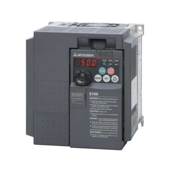
1 PRODUCT CHECKING AND PARTS IDENTIFICATION Unpack the inverter and check the capacity plate on the front cover and the rating plate on the inverter side face to ensure that the product agrees with your order and the inverter is intact. Inverter type FR - E740... -
Page 11: Installation And Wiring
(Refer to page 23) Moulded case circuit breaker (MCCB) or earth leakage circuit breaker (ELB), fuse Inverter (FR-E700) The breaker must be selected carefully since an in-rush current flows in the The life of the inverter is influenced by inverter at power on. -
Page 12: Peripheral Devices
Peripheral devices Peripheral devices Check the inverter type of the inverter you purchased. Appropriate peripheral devices must be selected according to the capacity. Refer to the following list and prepare appropriate peripheral devices: Moulded Case Circuit Breaker (MCCB) ∗1 Magnetic Contactor (MC) Motor Reactor or Earth Leakage Circuit Breaker... -
Page 13: Removal And Reinstallation Of The Cover
Removal and reinstallation of the cover Removal and reinstallation of the cover 2.2.1 Front cover FR-E720-3.7K or less, FR-E740-7.5K or less, FR-E720S, FR-E710W Removal (Example of FR-E740-3.7K) Remove the front cover by pulling it toward you in the direction of arrow. Reinstallation (Example of FR-E740-3.7K) To reinstall, match the cover to the inverter front and install it straight. - Page 14 Removal and reinstallation of the cover FR-E720-5.5K to 15K, FR-E740-11K, 15K Removal (Example of FR-E740-11K) 1) Loosen the installation screws of the front cover 1. 2) Remove the front cover 1 by pulling it toward you in the direction of arrow. 3) Remove the front cover 2 by pulling it toward you in the direction of arrow.
-
Page 15: Wiring Cover
Removal and reinstallation of the cover 2.2.2 Wiring cover Removal and reinstallation The cover can be removed easily by pulling it toward you. To reinstall, fit the cover to the inverter along the guides. FR-E720-1.5K to 3.7K FR-E720-0.1K to 0.75K FR-E740-0.4K to 3.7K FR-E720S-0.1K to 0.4K FR-E720S-0.75K to 2.2K... -
Page 16: Installation Of The Inverter And Instructions
Installation of the inverter and instructions Installation of the inverter and instructions Installation of the inverter Enclosure surface mounting Remove the front cover and wiring cover to fix the inverter to the surface. FR-E720-1.5K or more FR-E720-0.1K to 0.75K FR-E740-0.4K or more FR-E720S-0.1K to 0.4K FR-E720S-0.75K or more FR-E710W-0.1K to 0.4K... -
Page 17: Installation Of The Inverter And Instructions
Installation of the inverter and instructions The inverter consists of precision mechanical and electronic parts. Never install or handle it in any of the following conditions as doing so could cause an operation fault or failure. Vibration (5.9m/s or less at High temperature, Horizontal placement Direct sunlight... -
Page 18: Wiring
Wiring Wiring 2.4.1 Terminal connection diagram 1. DC reactor (FR-HEL) Sink logic When connecting a DC reactor, remove the Main circuit terminal jumper across P1 and P/+ *6 Terminal P1 is not available for single- Control circuit terminal Not available for single-phase 100V power phase 100V power input model. -
Page 19: Specification Of Main Circuit Terminal
Wiring 2.4.2 Specification of main circuit terminal Terminal Terminal Name Description Symbol R/L1, Connect to the commercial power supply. S/L2, AC power input Keep these terminals open when using the high power factor converter (FR-HC) or T/L3 ∗1 power regeneration common converter (FR-CV). U, V, W Inverter output Connect a three-phase squirrel-cage motor. -
Page 20: Terminal Arrangement Of The Main Circuit Terminal, Power Supply And The Motor Wiring
Wiring 2.4.3 Terminal arrangement of the main circuit terminal, power supply and the motor wiring Three-phase 200V class FR-E720-0.1K to 0.75K FR-E720-1.5K to 3.7K Jumper Jumper Screw size (M3.5) N/- P/+ Screw size (M4) R/L1 S/L2 T/L3 R/L1 S/L2 T/L3 Screw size Screw size (M4) - Page 21 Wiring Single-phase 200V class FR-E720S-0.1K to 0.4K FR-E720S-0.75K to 2.2K Jumper Jumper Screw size (M3.5) N/- P/+ Screw size (M4) R/L1 S/L2 R/L1 S/L2 Screw size Screw size (M4) (M3.5) Motor Power supply Power supply Motor Single-phase 100V class FR-E710W-0.1K to 0.4K FR-E710W-0.75K Jumper Jumper...
- Page 22 Wiring (1) Cable sizes etc., of the main control circuit terminals and earth (ground) terminals Select the recommended cable size to ensure that a voltage drop will be 2% max. If the wiring distance is long between the inverter and motor, a main circuit cable voltage drop will cause the motor torque to decrease especially at the output of a low frequency.
- Page 23 Wiring NOTE Tighten the terminal screw to the specified torque. A screw that has been tighten too loosely can cause a short circuit or malfunction. A screw that has been tighten too tightly can cause a short circuit or malfunction due to the unit breakage.
- Page 24 Wiring (3) Total wiring length The overall wiring length for connection of a single motor or multiple motors should be within the value in the table below. Pr. 72 PWM frequency selection 3.7K Setting 0.1K 0.2K 0.4K 0.75K 1.5K 2.2K or More (carrier frequency) 100V class,...
-
Page 25: Standard Control Circuit Terminal
Wiring 2.4.4 Standard control circuit terminal indicates that terminal functions can be selected using Pr. 178 to Pr. 184, Pr. 190 to Pr. 192 (I/O terminal function selection). ( Refer to the Instruction Manual (applied)). (1) Input signal Terminal Refer to Type Terminal Name Description... - Page 26 Wiring Terminal Refer to Type Terminal Name Description Rated Specifications Symbol Page Used as power supply when connecting potentiometer for frequency setting (speed setting) from outside of 5VDC Frequency setting power the inverter. permissible load current 59, 65 supply 10mA Refer to the chapter 4 of the Instruction Manual (applied)) Inputting 0 to 5VDC (or 0 to 10V) provides the...
- Page 27 Wiring (2) Output signal Terminal Reference Type Terminal Name Description Rated Specifications Symbol Page 1 changeover contact output indicates that the inverter Contact capacity:230VAC Instruction Relay output (fault protective function has activated and the output stopped. 0.3A A, B, C Manual output) Fault: discontinuity across B-C (continuity across A-C),...
-
Page 28: Changing The Control Logic
Wiring 2.4.5 Changing the control logic The input signals are set to sink logic (SINK) when shipped from the factory. To change the control logic, the jumper connector above the control terminal must be moved to the other position. To change to source logic, change the jumper connector in the sink logic (SINK) position to source logic (SOURCE) position using tweezers, a pair of long-nose pliers etc. - Page 29 Wiring (1) Sink logic type and source logic type In sink logic, a signal switches ON when a current flows from the corresponding signal input terminal. Terminal SD is common to the contact input signals. Terminal SE is common to the open collector output signals. In source logic, a signal switches ON when a current flows into the corresponding signal input terminal.
-
Page 30: Wiring Of Control Circuit
Wiring 2.4.6 Wiring of control circuit (1) Standard control circuit terminal layout Terminal screw size M3: (Terminal A, B, C) M2: (Other than the above) 4 RUN FU SE STF STR (2) Wiring method 1) Strip off the sheath of the wire of the control circuit to wire. Strip off the sheath about the size below. - Page 31 Wiring (3) Wiring instructions 1) Terminals SD, SE and 5 are common to the I/O signals. Do not earth (ground) them. 2) Use shielded or twisted wires for connection to the control circuit terminals and run them away from the main and power circuits (including the 200V relay sequence circuit).
-
Page 32: Connection To The Pu Connector
Wiring 2.4.7 Connection to the PU connector Using the PU connector, you can perform communication operation from the parameter unit (FR-PU07), enclosure surface operation panel (FR-PA07) or a personal computer etc. Refer to the figure below to open the PU connector cover. PU connector To open the cover Place a flathead screwdriver, etc. - Page 33 Pins No. 2 and 8 provide power to the parameter unit. Do not use these pins for RS-485 communication. When making RS-485 communication between the FR-E700 series, FR-E500 series and FR-S500 series, incorrect connection of pins No.2 and 8 (parameter unit power supply) of the above PU connector may result in the inverter malfunction or failure.
-
Page 34: Usb Connector
Wiring 2.4.8 USB connector A personal computer and an inverter can be connected with a USB (Ver1.1) cable. You can perform parameter setting and monitoring with the FR Configurator (FR-SW3-SETUP-W ). Interface Conforms to USB1.1 Transmission 12Mbps speed Wiring length Maximum 5m Connector USB mini B connector (receptacle mini B type) -
Page 35: When Using The Brake Resistor (Mrs Type, Mys Type, Fr-Abr)
When using the brake resistor (MRS type, MYS type, FR-ABR) When using the brake resistor (MRS type, MYS type, FR-ABR) It is recommended to configure a sequence, which shuts off power in the input side of the inverter by the external thermal relay as shown below, to prevent overheat and burnout of the brake resistor (MRS, MYS) and high duty brake resistor (FR- ABR) in case the regenerative brake transistor is damaged. -
Page 36: Power-Off And Magnetic Contactor (Mc)
Power-OFF and magnetic contactor (MC) Power-OFF and magnetic contactor (MC) (1) Inverter input side magnetic contactor (MC) On the inverter input side, it is recommended to provide an MC for the following purposes. (Refer to page 3 for selection.) 1) To release the inverter from the power supply when the fault occurs or when the drive is not functioning (e.g. emergency stop operation). -
Page 37: Precautions For Use Of The Inverter
Precautions for use of the inverter Precautions for use of the inverter The FR-E700 series is a highly reliable product, but incorrect peripheral circuit making or operation/handling method may shorten the product life or damage the product. Before starting operation, always recheck the following items. - Page 38 Precautions for use of the inverter (12) Do not apply a voltage higher than the permissible voltage to the inverter I/O signal circuits. Application of a voltage higher than the permissible voltage to the inverter I/O signal circuits or opposite polarity may damage the I/O devices.
-
Page 39: Failsafe Of The System Which Uses The Inverter
Failsafe of the system which uses the inverter Failsafe of the system which uses the inverter When a fault occurs, the inverter trips to output a fault signal. However, a fault output signal may not be output at an inverter fault occurrence when the detection circuit or output circuit fails, etc. -
Page 40: Drive The Motor
Step of operation 3 DRIVE THE MOTOR Step of operation The inverter needs frequency command and start command. Turning the start command on starts the motor rotating and the frequency command (set frequency) determines the motor speed. Refer to the flow chart below to make setting. Step of operation Installation/mounting Frequency command... -
Page 41: Operation Panel
Operation panel Operation panel 3.2.1 Names and functions of the operation panel The operation panel cannot be removed from the inverter. Operating status display Operation mode indication ∗ PU: Lit to indicate PU operation mode. Lit or flicker during inverter operation. EXT: Lit to indicate External operation mode. -
Page 42: Basic Operation (Factory Setting)
Operation panel 3.2.2 Basic operation (factory setting) Operation mode switchover At powering on (external operation mode) PU Jog operation mode (Example) PU operation mode Value change and frequency flicker. (output frequency monitor) Frequency setting has been written and completed!! STOP Output current monitor Output voltage monitor Display the... -
Page 43: Easy Operation Mode Setting (Easy Setting Mode)
Operation panel 3.2.3 Easy operation mode setting (easy setting mode) Setting of Pr. 79 Operation mode selection according to combination of the start command and speed command can be easily made. Operation Start command: external (STF/STR), frequency command: operate with example Operation Display... -
Page 44: Operation Lock (Press [Mode] For A While (2S))
Operation panel 3.2.4 Operation lock (Press [MODE] for a while (2s)) Operation using the setting dial and key of the operation panel can be set invalid to prevent parameter change, and unexpected start or frequency setting. Set "10 or 11" in Pr. 161, then press for 2s to make the setting dial and key operation invalid. -
Page 45: Monitoring Of Output Current And Output Voltage
Operation panel 3.2.5 Monitoring of output current and output voltage POINT Monitor display of output frequency, output current and output voltage can be changed by pressing during monitoring mode. Operation Display Press during operation to choose the Hz is lit output frequency monitor Independently whether the inverter is running in any operation mode or at a stop, the output... -
Page 46: Change The Parameter Setting Value
Operation panel 3.2.8 Change the parameter setting value Changing Change the Pr. 1 Maximum frequency setting. example Operation Display Screen at powering ON The monitor display appears. PU indication is lit. Press to choose the PU operation mode. PRM indication is lit. Press to choose the parameter setting mode. -
Page 47: Parameter Clear/All Parameter Clear
Operation panel 3.2.9 Parameter clear/all parameter clear POINT Set "1" in Pr.CL Parameter clear, ALLC all parameter clear to initialize all parameters. (Parameters are not cleared when "1" is set in Pr. 77Parameter write selection.) Refer to the extended parameter list on page 74 for parameters cleared with this operation. Operation Display Screen at powering ON... -
Page 48: Initial Value Change List
Operation panel 3.2.10 Initial value change list Displays and sets the parameters changed from the initial value. Operation Display Screen at powering ON The monitor display appears. PU indication is lit. Press to choose the PU operation mode. PRM indication is lit. Press to choose the parameter setting mode. -
Page 49: Before Operation
Before operation Before operation 3.3.1 Simple mode parameter list For simple variable-speed operation of the inverter, the initial setting of the parameters may be used as they are. Set the necessary parameters to meet the load and operational specifications. Parameter setting, change and check can be made from the operation panel. -
Page 50: Overheat Protection Of The Motor By The Inverter (Pr. 9)
Before operation 3.3.2 Overheat protection of the motor by the inverter (Pr. 9) Set the rated motor current in Pr. 9 Electronic thermal O/L relay to protect the motor from overheat. Parameter Name Initial Value Setting Range Description Number Electronic thermal O/L Rated Inverter 0 to 500A Set the rated motor current. - Page 51 Before operation Electronic thermal relay function operation characteristic This function detects the overload (overheat) Pr. 9 = 100% setting of inverter rating*2 of the motor, stops the operation of the Pr. 9 = 50% setting of inverter rating*1, 2 inverter's output transistor, and stops the output.
-
Page 52: When The Rated Motor Frequency Is 50Hz (Pr. 3)
Before operation 3.3.3 When the rated motor frequency is 50Hz (Pr. 3) First, check the motor rating plate. If a frequency given on the rating plate is "50Hz" only, always set Pr. 3 Base frequency to "50Hz". Leaving the base frequency unchanged from "60Hz" may make the voltage low and the torque insufficient. It may result in an inverter trip (E.OC ) due to overload. -
Page 53: Increase The Starting Torque (Pr. 0)
Before operation 3.3.4 Increase the starting torque (Pr. 0) Set this parameter when "the motor with a load will not rotate", "an alarm [OL] is output, resulting in an inverter trip due to [OC1]," etc. Parameter Name Initial Value Setting Range Description Number 0.1K to 0.75K... -
Page 54: Limit The Maximum And Minimum Output Frequency (Pr. 1, Pr. 2)
Before operation 3.3.5 Limit the maximum and minimum output frequency (Pr. 1, Pr. 2) Motor speed can be limited. Parameter Name Initial Value Setting Range Description Number Maximum frequency 120Hz 0 to 120Hz Set the upper limit of the output frequency. Minimum frequency 0 to 120Hz Set the lower limit of the output frequency. -
Page 55: Change Acceleration And Deceleration Time Of The Motor (Pr. 7, Pr. 8)
Before operation 3.3.6 Change acceleration and deceleration time of the motor (Pr. 7, Pr. 8) Set in Pr. 7 Acceleration time a larger value for a slower speed increase and a smaller value for a faster speed increase. Set in Pr. 8 Deceleration time a larger value for a slower speed decrease and a smaller value for a faster speed decrease. Parameter Name Initial Value... -
Page 56: Selection Of The Start Command And Frequency Command Locations (Pr. 79)
Before operation 3.3.7 Selection of the start command and frequency command locations (Pr. 79) Select the start command location and frequency command location. POINT Setting value "1" to "4" can be changed in the easy setting mode. (Refer to page 34) Indication Parameter Initial... -
Page 57: Large Starting Torque And Low Speed Torque Are Necessary (Advanced Magnetic Flux Vector Control, General-Purpose Magnetic Flux Vector Control) (Pr. 71, Pr. 80, Pr. 81, Pr. 800)
Before operation 3.3.8 Large starting torque and low speed torque are necessary (Advanced magnetic flux vector control, General-purpose magnetic flux vector control) (Pr. 71, Pr. 80, Pr. 81, Pr. 800) AD MFVC AD MFVC AD MFVC GP MFVC GP MFVC GP MFVC Advanced magnetic flux vector control can be selected by setting the capacity, poles and type of the motor used in Pr. -
Page 58: Test Run
Before operationPerform secure wiring. (Refer to page 9) Set the motor. (Pr. 71) Pr. 71 Setting ∗1 Motor Remarks Mitsubishi standard SF-JR 0 (initial value) motor SF-HR Mitsubishi high ∗2 Others Offline auto tuning is necessary. -
Page 59
Before operation
Perform secure wiring. (Refer to page 9) Set the motor.(Pr. 71) Pr. 71 Setting ∗1 Motor Remarks Mitsubishi standard SF-JR 0 (initial value) motor SF-HR Mitsubishi high ∗2 Others Offline auto tuning is necessary. efficiency motor SF-JRCA 4P Mitsubishi constant-... -
Page 60: To Exhibit The Best Performance Of The Motor Performance (Offline Auto Tuning) (Pr. 71, Pr. 83, Pr. 84, Pr. 96)
Before operation 3.3.9 To exhibit the best performance of the motor performance (offline auto tuning) (Pr. 71, Pr. 83, Pr. 84, Pr. 96) The motor performance can be maximized with offline auto tuning. What is offline auto tuning? When performing Advanced magnetic flux vector control or General-purpose magnetic flux vector control, the motor can be run with the optimum operating characteristics by automatically measuring the motor constants (offline auto tuning) even when each motor constants differs, other manufacturer's motor is used, or the wiring length is long. - Page 61 Before operation (1) Before performing offline auto tuning Check the following before performing offline auto tuning. Make sure Advanced magnetic flux vector control or General-purpose magnetic flux vector control (Pr. 80, Pr. 81) is selected. (Tuning can be performed even under V/F control selected by turning ON X18.) A motor should be connected.
- Page 62 Before operation (3) Execution of tuning POINT Before performing tuning, check the monitor display of the operation panel or parameter unit (FR-PU04/FR-PU07) if the inverter is in the status for tuning. (Refer to 2) below) When the start command is turned ON under V/F control, the motor starts.
- Page 63 Before operation 3) When offline auto tuning ends, press of the operation panel during PU operation. For external operation, turn OFF the start signal (STF signal or STR signal) once. This operation resets the offline auto tuning and the PU's monitor display returns to the normal indication. (Without this operation, next operation cannot be started.) REMARKS Do not change the Pr.
-
Page 64: Start/Stop From The Operation Panel (Pu Operation)
Start/stop from the operation panel (PU operation) Start/stop from the operation panel (PU operation) POINT From where is the frequency command given? Operation at the frequency set in the frequency setting mode of the operation panel refer to 3.4.1 (Refer to page 55) Operation using the setting dial as the potentiometer refer to 3.4.2 (Refer to page 57) Change of frequency with ON/OFF switches connected to terminals... - Page 65 Start/stop from the operation panel (PU operation) REMARKS Operation cannot be performed at the set frequency ... Why? Did you carry out step 4 within 5s after step 3? (Did you press within 5s after turning The frequency does not change by turning ...
-
Page 66: Use The Setting Dial Like A Potentiometer To Perform Operation
Start/stop from the operation panel (PU operation) 3.4.2 Use the setting dial like a potentiometer to perform operation. POINT Set "1" (setting dial potentiometer mode) in Pr. 161 Frequency setting/key lock operation selection. Changing Changing the frequency from 0Hz to 60Hz during operation example Operation Display... -
Page 67: Use Switches To Give A Frequency Command (Multi-Speed Setting)
Start/stop from the operation panel (PU operation) 3.4.3 Use switches to give a frequency command (multi-speed setting) POINT to give a start command. Pr. 79 Operation mode selection must be set to "4" (External/PU combined operation mode 2). The initial values of the terminals RH, RM, RL are 60Hz, 30Hz, and 10Hz. (Use Pr. 4, Pr. 5 and Pr. 6 (Refer to page 63) to change.) Operation at 7-speed can be performed by turning ON two (or three) terminals simultaneously. -
Page 68: Perform Frequency Setting By Analog (Voltage Input)
Start/stop from the operation panel (PU operation) 3.4.4 Perform frequency setting by analog (voltage input) POINT to give a start command. Pr. 79 Operation mode selection must be set to "4" (External/PU combined operation mode 2). [Connection diagram] (The inverter supplies 5V of power to the frequency setting potentiometer. (terminal 10)) Inverter R/L1 Three-phase AC... -
Page 69: Perform Frequency Setting By Analog (Current Input)
Start/stop from the operation panel (PU operation) 3.4.5 Perform frequency setting by analog (current input) POINT to give a start command. Turn the AU signal ON. Pr. 79 Operation mode selection must be set to "4" (External/PU combined operation mode 2). [Connection diagram] Inverter R/L1... -
Page 70: Make A Start And Stop With Terminals (External Operation)
Make a start and stop with terminals (external operation) Make a start and stop with terminals (external operation) POINT From where is the frequency command given? Operation at the frequency set in the frequency setting mode of the operation panel refer to 3.5.1 (Refer to page 61) Give a frequency command by switch (multi-speed setting) refer to 3.5.2 (Refer to page 63) - Page 71 Make a start and stop with terminals (external operation) REMARKS Pr. 178 STF terminal function selection must be set to "60" (or Pr. 179 STR terminal function selection must be set to "61"). (all are initial values) When Pr. 79 Operation mode selection is set to "3", multi-speed operation (Refer to page 63) is also valid. Pressing to stop the motor and the display shows 1.
-
Page 72: Use Switches To Give A Start Command And A Frequency Command (Multi-Speed Setting) (Pr. 4 To Pr. 6)
Make a start and stop with terminals (external operation) 3.5.2 Use switches to give a start command and a frequency command (multi-speed setting) (Pr. 4 to Pr. 6) POINT Start command by terminal STF (STR)-SD Frequency command by terminal RH, RM, RL-SD [EXT] must be lit. - Page 73 Make a start and stop with terminals (external operation) REMARKS [EXT] is not lit even when is pressed...Why? Switchover of the operation mode with is valid when Pr. 79 = "0" (initial value). 50Hz for the RH, 30Hz for the RM and 10Hz for the RL are not output when they are turned ON...Why? Check for the setting of Pr.
-
Page 74: Perform Frequency Setting By Analog (Voltage Input)
Make a start and stop with terminals (external operation) 3.5.3 Perform frequency setting by analog (voltage input) [Connection diagram] (The inverter supplies 5V of power to the frequency setting potentiometer. (terminal 10)) Inverter Three-phase AC R/L1 S/L2 Motor power supply T/L3 Forward rotation start Reverse rotation start... - Page 75 Make a start and stop with terminals (external operation) POINT When you always want to operate in the External operation mode at powering ON or when you want to save the trouble of input, set "2" (External operation mode) in Pr. 79 Operation mode selection to choose External operation mode always.
-
Page 76: Change The Frequency (60Hz) At The Maximum Voltage Input (5V Initial Value)
Make a start and stop with terminals (external operation) 3.5.4 Change the frequency (60Hz) at the maximum voltage input (5V initial value) < How to change the maximum frequency> Changing When you use the 0 to 5VDC input and want to change the frequency at 5V from 60Hz (initial value) to 50Hz, example set "50Hz"... -
Page 77: Perform Frequency Setting By Analog (Current Input)
Make a start and stop with terminals (external operation) 3.5.5 Perform frequency setting by analog (current input) POINT Switch terminal STF(STR)-SD ON to give a start command. Turn the AU signal ON. Set "2" (External operation mode) in Pr. 79 Operation mode selection . [Connection diagram] Inverter R/L1... - Page 78 Make a start and stop with terminals (external operation) REMARKS Set "4" in Pr.178 to Pr.184 (input terminal function selection) to assign terminal 4 input selection signal (AU) to the input terminal. Refer to the chapter 4 of the Instruction Manual (applied)). The motor will not rotate...Why? Check that [EXT] is lit.
-
Page 79: Change The Frequency (60Hz) At The Maximum Current Input (At 20Ma, Initial Value)
Make a start and stop with terminals (external operation) 3.5.6 Change the frequency (60Hz) at the maximum current input (at 20mA, initial value)When you use the 4 to 20mA input and want to change the frequency at 20mA from 60Hz (initial value) to 50Hz, Changing example set "50Hz"... -
Page 80: Parameter List
Parameter list Parameter list 3.6.1 List of parameters classified by purpose of use Set parameters according to the operating conditions. The following list indicates purpose of use and corresponding parameters. Purpose of Use Parameter Number Control mode Change the control method Pr. - Page 81 Parameter list Purpose of Use Parameter Number Speed display and speed setting Pr. 37 Change of DU/PU monitor descriptions Pr. 52, Pr. 170, Pr. 171, Pr. 563, Pr. 564 Cumulative monitor clear Monitor display and Change of the monitor output from terminal monitor output signal Pr.
- Page 82 Parameter list Purpose of Use Parameter Number PID control Pr. 127 to Pr. 134 Special operation and Dancer control Pr. 128 to Pr. 134 frequency control Droop control Pr. 286, Pr. 287 Increase cooling fan life Pr. 244 To determine the maintenance time of parts. Pr.
-
Page 83: Parameter List
Parameter list 3.6.2 Parameter list indicates simple mode parameters..V/F control, ..Advanced magnetic flux vector control AD MFVC AD MFVC AD MFVC ..General-purpose magnetic flux vector control GP MFVC GP MFVC GP MFVC (Parameters without any indication are valid for all control.) "... - Page 84 Parameter list Parameter Incre- Initial Param Param Param Function Name Range Description eter eter eter ments Value Copy Clear Clear Motor acceleration time. 5/10/ 0.1/ 0 to 3600/ * The setting range differs according to the Acceleration time 0.01s 360s inverter capacity ∗...
- Page 85 Parameter list Parameter Incre- Initial Param Param Param Function Name Range Description eter eter eter ments Value Copy Clear Clear For constant torque load For reduced-torque load Load pattern Boost for reverse selection rotation 0% For constant-torque elevators Boost for forward rotation 0% Jog frequency 0.01Hz...
- Page 86 Parameter list Parameter Incre- Initial Param Param Param Function Name Range Description eter eter eter ments Value Copy Clear Clear 24 to 27 Refer to Pr.4 to Pr.6. —— Linear acceleration/ deceleration Acceleration/ S-pattern acceleration/deceleration A deceleration pattern selection S-pattern acceleration/deceleration B Without regenerative function, Brake resistor (MRS type, MYS type), Brake unit (FR-BU2),...
- Page 87 Parameter list Parameter Incre- Initial Param Param Param Function Name Range Description eter eter eter ments Value Copy Clear Clear Select monitor to be displayed on the operation panel and parameter unit and monitor to be output to the terminal FM. 0: Output frequency (Pr.52) 0, 5, 7 to 1: Output frequency (Pr.54)
- Page 88 Parameter list Parameter Incre- Initial Param Param Param Function Name Range Description eter eter eter ments Value Copy Clear Clear Frequency Full-scale value to output the output monitoring 0.01Hz 60Hz 0 to 400Hz frequency monitor value to terminal FM. reference Current Rated Full-scale value to output the output...
- Page 89 Parameter list Parameter Incre- Initial Param Param Param Function Name Range Description eter eter eter ments Value Copy Clear Clear RH, RM, RL signal Frequency setting function storage function Multi-speed setting — Remote setting Remote function Remote setting selection No (Turning STF/ STR OFF clears Remote setting remotely-set...
- Page 90 Parameter list Parameter Incre- Initial Param Param Param Function Name Range Description eter eter eter ments Value Copy Clear Clear Thermal characteristics of a standard motor Thermal characteristics of the Mitsubishi constant-torque motor Thermal characteristic of Mitsubishi high efficiency standard motor (SF-HR) Thermal characteristic of Mitsubishi constant torque motor (SF-HRCA) Standard motor...
- Page 91 Parameter list Parameter Incre- Initial Param Param Param Function Name Range Description eter eter eter ments Value Copy Clear Clear Terminal 2 input Polarity reversible 0 to 10V Analog input Not used × 0 to 5V selection 0 to 10V With 0 to 5V Terminal 4 input 4 to 20mA...
-
Page 92: Auto Tuning
Parameter list Parameter Incre- Initial Param Param Param Function Name Range Description eter eter eter ments Value Copy Clear Clear Tuning data (The value measured by offline auto tuning is automatically set.) 0 to 500A∗ * The range differs according to the Pr. 71 setting. Motor excitation ×... - Page 93 Parameter list Parameter Incre- Initial Param Param Param Function Name Range Description eter eter eter ments Value Copy Clear Clear Inverter station number. Set the inverter station numbers when two or more inverters are connected to one 0 to 31 communication personal computer.
- Page 94 Parameter list Parameter Incre- Initial Param Param Param Function Name Range Description eter eter eter ments Value Copy Clear Clear Terminal 2 Frequency of terminal 2 input gain frequency setting × 0.01Hz 60Hz 0 to 400Hz (maximum). gain frequency Terminal 4 Frequency of terminal 4 input gain frequency setting ×...
- Page 95 Parameter list Parameter Incre- Initial Param Param Param Function Name Range Description eter eter eter ments Value Copy Clear Clear PID control Frequency at which the control is 0 to 400Hz automatically changed to PID control. automatic 0.01Hz 9999 switchover 9999 Without PID automatic switchover function frequency...
- Page 96 Parameter list Parameter Incre- Initial Param Param Param Function Name Range Description eter eter eter ments Value Copy Clear Clear Japanese English Germany PU display French language × × Spanish selection Italian Swedish Finnish PA02 Built-in frequency setting Valid when the Built-in potentiometer valid operation panel...
- Page 97 Parameter list Parameter Incre- Initial Param Param Param Function Name Range Description eter eter eter ments Value Copy Clear Clear 162, 165 Refer to Pr. 57. 168, 169 Parameter for manufacturer setting. Do not set. —— 170, 171 Refer to Pr. 52. 172 to 174 Refer to Pr.
- Page 98 Parameter list Parameter Incre- Initial Param Param Param Function Name Range Description eter eter eter ments Value Copy Clear Clear 0, 100: Inverter running (RUN) 1, 101: Up to frequency (SU) 3, 103: Overload alarm (OL) RUN terminal 4, 140: Output frequency detection (FU) ×...
- Page 99 Parameter list Parameter Incre- Initial Param Param Param Function Name Range Description eter eter eter ments Value Copy Clear Clear Without ground fault detection Earth (ground) fault detection at With ground fault detection start The motor is coasted STF signal: Forward to a stop when the rotation start 0 to 100s...
- Page 100 Parameter list Parameter Incre- Initial Param Param Param Function Name Range Description eter eter eter ments Value Copy Clear Clear Coasts to stop. When undervoltage or power failure occurs, the output is shut off. Decelerates to a stop when undervoltage Power failure stop or a power failure occurs.
- Page 101 Parameter list Parameter Incre- Initial Param Param Param Function Name Range Description eter eter eter ments Value Copy Clear Clear Droop control is invalid Droop gain 0.1% 0.1 to Drooping amount at the rated torque with 100% respect to the rated motor frequency. Droop filter time Time constant of the primary delay filter 0.01s...
- Page 102 Parameter list Parameter Incre- Initial Param Param Param Function Name Range Description eter eter eter ments Value Copy Clear Clear Remote output data clear at powering OFF Remote output data Remote output data clear at inverter retention at powering reset Remote output selection Remote output data...
- Page 103 Parameter list Parameter Incre- Initial Param Param Param Function Name Range Description eter eter eter ments Value Copy Clear Clear Refer to Pr.80. —— Refer to Pr.84. —— Refer to Pr.251. —— Regeneration avoidance function invalid Regeneration Regeneration avoidance function is always avoidance valid operation...
- Page 104 Parameter list Parameter Incre- Initial Param Param Param Function Name Range Description eter eter eter ments Value Copy Clear Clear Contrast adjustment of the LCD of the parameter unit (FR-PU04/FR-PU07) can PU contrast be performed. × 0 to 63 adjustment 0: Light ↓...
-
Page 105: Troubleshooting
Reset method of protective function 4 TROUBLESHOOTING When a fault occurs in the inverter, the inverter trips and the PU display automatically changes to any of the following fault or alarm indications. If the fault does not correspond to any of the following faults or if you have any other problem, please contact your sales representative. -
Page 106: List Of Fault Or Alarm Indications
List of fault or alarm indications List of fault or alarm indications Refer Refer Operation Panel Operation Panel Name Name Indication Indication Page Page E.ILF ∗ Input phase loss E--- Faults history E.OLT Stall prevention HOLD Operation panel lock Brake transistor alarm E. -
Page 107: Causes And Corrective Actions
Causes and corrective actions Causes and corrective actions (1) Error message A message regarding operational troubles is displayed. Output is not shutoff. Operation panel HOLD indication Name Operation panel lock Description Operation lock mode is set. Operation other than is invalid. (Refer to page 35) Check point -- - - -- - -- - - -- - Corrective action... - Page 108 Causes and corrective actions (2) Warnings When a warning occurs, the output is not shut off. Operation panel FR-PU04 indication FR-PU07 Name Stall prevention (overcurrent) When the output current (output torque when Pr. 277 Stall prevention current switchover = "1") of the inverter exceeds the stall prevention operation level (Pr.
- Page 109 Causes and corrective actions Operation panel FR-PU04 indication FR-PU07 Name Regenerative brake prealarm Appears if the regenerative brake duty reaches or exceeds 85% of the Pr. 70 Special regenerative brake duty value. When the setting of Pr. 70 Special regenerative brake duty is the initial value (Pr. 70 = "0"), this warning does not occur. If the regenerative brake duty reaches 100%, a regenerative overvoltage (E.
- Page 110 Causes and corrective actions (4) Fault When a fault occurs, the inverter trips and a fault signal is output. Operation panel FR-PU04 E.OC1 OC During Acc indication FR-PU07 Name Overcurrent trip during acceleration When the inverter output current reaches or exceeds approximately 230% of the rated current during acceleration, the Description protective circuit is activated and the inverter trips.
- Page 111 Causes and corrective actions Operation panel FR-PU04 E.OV2 Stedy Spd OV indication FR-PU07 Name Regenerative overvoltage trip during constant speed If regenerative energy causes the inverter's internal main circuit DC voltage to reach or exceed the specified value, Description the protective circuit is activated to stop the inverter output. The circuit may also be activated by a surge voltage produced in the power supply system.
- Page 112 Causes and corrective actions Operation panel FR-PU04 E.FIN H/Sink O/Temp indication FR-PU07 Name Fin overheat If the heatsink overheats, the temperature sensor is actuated and the inverter trips. The FIN signal can be output when the temperature becomes approximately 85% of the heatsink overheat protection operation temperature.
- Page 113 Causes and corrective actions Operation panel FR-PU04 E.LF E.LF indication FR-PU07 Name Output phase loss If one of the three phases (U, V, W) on the inverter's output side (load side) is lost during inverter operation (except Description during DC injection brake operation and when output frequency is under 1Hz), inverter stops the output. Whether the protective function is used or not is set with Pr.
- Page 114 Causes and corrective actions Operation Panel FR-PU04 Fault 14 E.PE2 FR-PU07 PR storage alarm Indication Name Internal board fault Description When a combination of control board and main circuit board is wrong, the inverter is tripped. Check point — Please contact your sales representative. Corrective action (For parts replacement, consult the nearest Mitsubishi FA Center.) Operation panel...
- Page 115 Causes and corrective actions Operation panel FR-PU04 Fault 14 E.AIE FR-PU07 Analog in error indication Name Analog input fault Appears if voltage(current) is input to terminal 4 when the setting in Pr.267 Terminal 4 input selection and the setting of Description voltage/current input switch are different.
-
Page 116: Correspondences Between Digital And Actual Characters
Correspondences between digital and actual characters Correspondences between digital and actual characters There are the following correspondences between the actual alphanumeric characters and the digital characters displayed on the operation panel: Actual Digital Actual Digital Actual Digital... -
Page 117: Check And Clear Of The Faults History
Check and clear of the faults history Check and clear of the faults history (1) Check for the faults history Monitor/frequency setting Parameter setting [Operation panel is [Parameter setting change] used for operation] Faults history [Operation for displaying the faults history] Eight past faults can be displayed with the setting dial. - Page 118 Check and clear of the faults history (2) Clearing procedure POINT Set "1" in Er.CL Fault history clear to clear the faults history. Operation Display Screen at powering ON The monitor display appears. PRM indication is lit. Press to choose the parameter setting mode. (The parameter number read previously appears.) Turn until...
-
Page 119: Check First When You Have Some Troubles
Check first when you have some troubles Check first when you have some troubles POINT If the cause is still unknown after every check, it is recommended to initialize the parameters (initial value) then set the required parameter values and check again. Refer to the Instruction Manual (Applied) for in "Refer to page"... - Page 120 Check first when you have some troubles Refer Check Possible Cause Countermeasures points page Increase Pr. 0 setting by 0.5% increments while Pr. 0 Torque boost setting is improper when V/F control is observing the rotation of a motor. used. If that makes no difference, decrease the setting.
-
Page 121: Motor Or Machine Is Making Abnormal Acoustic Noise
Check first when you have some troubles 4.6.2 Motor or machine is making abnormal acoustic noise Refer Check Possible Cause Countermeasures points page Input Take countermeasures against EMI. signal Disturbance due to EMI when frequency command is Parameter given from analog input (terminal 2, 4). Increase the Pr. -
Page 122: Motor Rotates In The Opposite Direction
Check first when you have some troubles 4.6.5 Motor rotates in the opposite direction Refer Check Possible Cause Countermeasures points page Main Phase sequence of output terminals U, V and W is Connect phase sequence of the output cables (terminal incorrect. -
Page 123: Speed Varies During Operation
Check first when you have some troubles 4.6.8 Speed varies during operation When Advanced magnetic flux vector control or the slip compensation is selected, the output frequency varies between 0 and 2Hz as load fluctuates.This is a normal operation and not a fault. Refer Check Possible Cause... -
Page 124: Operation Panel Display Is Not Operating
Check first when you have some troubles 4.6.10 Operation panel display is not operating Refer Check Possible Cause Countermeasures points page Check for the wiring and the installation. Main Wiring or installation is improper. Make sure that the connector is fitted securely across Circuit terminal P/+ and P1. -
Page 125: Speed Does Not Accelerate
Check first when you have some troubles 4.6.12 Speed does not accelerate Refer Check Possible Cause Countermeasures points page Check if the start command and the frequency Start command and frequency command are chattering. — command are correct. Input The wiring length used for analog frequency command Perform analog input bias/gain calibration. -
Page 126: Precautions For Maintenance And Inspection
Inspection items 5 PRECAUTIONS FOR MAINTENANCE AND INSPECTION The inverter is a static unit mainly consisting of semiconductor devices. Daily inspection must be performed to prevent any fault from occurring due to the adverse effects of the operating environment, such as temperature, humidity, dust, dirt and vibration, changes in the parts with time, service life, and other factors. -
Page 127: Daily And Periodic Inspection
Inspection items 5.1.3 Daily and periodic inspection Interval Area of Corrective Action at Customer's Periodic Inspection Item Description Daily Inspection Alarm Occurrence Check ∗2 Surrounding Check the surrounding air temperature, Improve environment environment humidity, dirt, corrosive gas, oil mist, etc. Check alarm location and General Overall unit... -
Page 128: Display Of The Life Of The Inverter Parts
Inspection items 5.1.4 Display of the life of the inverter parts The self-diagnostic alarm is output when the life span of the control circuit capacitor, cooling fan and each parts of the inrush current limit circuit is near its end. It gives an indication of replacement time. The life alarm output can be used as a guideline for life judgement. - Page 129 Inspection items (2) Measuring method of life of the main circuit capacitor If the value of capacitor capacity measured before shipment is considered as 100%, Pr. 255 bit1 is turned ON when the measured value falls below 85%. Measure the capacitor capacity according to the following procedure and check the deterioration level of the capacitor capacity.
-
Page 130: Cleaning
Inspection items 5.1.5 Cleaning Always run the inverter in a clean status. When cleaning the inverter, gently wipe dirty areas with a soft cloth immersed in neutral detergent or ethanol. NOTE Do not use solvent, such as acetone, benzene, toluene and alcohol, as they will cause the inverter surface paint to peel off. The display, etc. - Page 131 Inspection items Removal 1) Push the hooks from above and remove the fan cover. 3.7K or less 5.5K or more 2) Disconnect the fan connectors. 3) Remove the fan. 5.5K or more 3.7K or less Fan cover Fan cover Fan connection connector Fan connection connector...
-
Page 132
Inspection items Reinstallation 1) After confirming the orientation of the fan, reinstall the fan so that the arrow on the left of "AIR FLOW" faces up. AIR FLOW
2) Reconnect the fan connectors. 3) When wiring, avoid the cables being caught by the fan. 5.5K or more 3.7K or less 4) Reinstall the fan cover. -
Page 133: Inverter Replacement
Inspection items (2) Smoothing capacitors A large-capacity aluminum electrolytic capacitor is used for smoothing in the main circuit DC section, and an aluminum electrolytic capacitor is used for stabilizing the control power in the control circuit. Their characteristics are deteriorated by the adverse effects of ripple currents, etc. -
Page 134: Specifications
Although the FR-E700 series has the built-in inrush current limit circuit, select the DC power supply considering the inrush current at powering ON as the inrush current four times of the rated inverter flows at powering ON. - Page 135 Rating Single-phase 200V power supply Type FR-E720S- K 0.75 Applicable motor capacity (kW) 0.75 ∗1 Rated capacity (kVA) ∗2 11.0 Rated current (A) ∗6 (0.8) (1.4) (2.5) (4.1) (7.0) (10.0) Overload current rating 150% 60s, 200% 3s (inverse-time characteristics) ∗3 Rated output voltage Three-phase 200 to 240V ∗4...
-
Page 136: Common Specifications
Common specifications Common specifications Soft-PWM control/high carrier frequency PWM control (V/F control, Advanced magnetic flux vector control, Control method General-purpose magnetic flux vector control, Optimum excitation control can be selected) Output frequency range 0.2 to 400Hz 0.06Hz/60Hz (terminal2, 4: 0 to 10V/10bit) Analog input Frequency setting 0.12Hz/60Hz (terminal2, 4: 0 to 5V/9bit) -
Page 137: Outline Dimension Drawings
Outline dimension drawings Outline dimension drawings FR-E720-0.1K to 0.75K FR-E720S-0.1K to 0.4K FR-E710W-0.1K to 0.4K When used with the plug-in option φ5 hole Capacity plate D2 ∗ When the FR-A7NC E kit is mounted, a terminal block protrudes making the depth approx. 2mm greater. Inverter Type FR-E720-0.1K, 0.2K FR-E720S-0.1K, 0.2K... - Page 138 Outline dimension drawings FR-E720-3.7K When used with the plug-in option 2-φ5 hole Rating Rating plate plate Capacity plate 66.5 66.5 142.5 157.6 * When the FR-A7NC E kit is mounted, a terminal block protrudes making the depth approx. 2mm greater. (Unit: mm) FR-E720-5.5K to 15K When used with the plug-in option...
- Page 139 Outline dimension drawings FR-E740-0.4K to 3.7K FR-E720S-2.2K When used with the plug-in option 2- φ 5 hole Rating Rating plate plate Capacity plate D2 *2 ∗1 FR-E740-0.4K, 0.75K are not provided with the cooling fan. ∗2 When the FR-A7NC E kit is mounted, a terminal block protrudes making the depth approx.
- Page 140 Outline dimension drawings FR-E740-11K, 15K When used with the plug-in option 2-φ6 hole Rating Rating plate plate 10.5 10.5 84.5 84.5 Capacity 205.1 * plate When the FR-A7NC E kit is mounted, a terminal block protrudes making the depth approx. 2mm greater. (Unit: mm)
- Page 141 Outline dimension drawings Parameter unit (option) (FR-PU07) Outline drawing Panel cut dimension drawing < > < > 25.05 (14.2) (11.45) Air-bleeding hole 4-R1 4-φ4 hole 26.5 26.5 Effective depth of the installation screw hole 5.0) M3 screw *2 ∗1 When installing the FR-PU07 on the enclosure, etc., remove screws or fix the screws to the FR-PU07 with M3 nuts.
-
Page 142: Appendix
4) Setup software (FR-SW0-SETUP, FR-SW1-SETUP, FR-SW2-SETUP) can not be used. (2) Instructions for continuous use of the FR-PU04 (parameter unit) For the FR-E700 series, many functions (parameters) have been added. User initial value list and user clear of the HELP function can not be used. - Page 143 (4) Main differences and compatibilities with the FR-E500 Series Item FR-E500 FR-E700 V/F control V/F control General-purpose magnetic flux vector control Control method General-purpose magnetic flux vector control Advanced magnetic flux vector control Optimum excitation control Torque boost (Pr. 0) initial value FR-E720-1.5K to 3.7K: 4%...
- Page 144 Appendix 2 Instructions for compliance with the European Directives (1) EMC Directive 1) Our view of transistorized inverters for the EMC Directive A transistorized inverter is a component designed for installation in an enclosure and for use with the other equipment to control the equipment/device.
- Page 145 To use the inverter outside of an enclosure in the environment of pollution degree 2, fix a fan cover with fan cover fixing screws enclosed. 3.7K or less 5.5K or more Fan cover Fan cover fixing screw fixing screws Fan cover Fan cover Fan connection connector...
- Page 146 ∗Provide the appropriate UL and cUL listed Class T type fuse that is suitable for branch circuit protection in accordance with the table below. FR-E720- 0.75 Rated fuse voltage(V) 240V or more Without power factor Fuse Maximum improving reactor allowable rating With power factor (A)∗...
-
Page 147: Motor Overload Protection
Appendix 3 Instructions for UL and cUL (Standard to comply with: UL 508C, CSA C22.2 No. 14) 1. General Precaution The bus capacitor discharge time is 10 minutes. Before starting wiring or inspection, switch power off, wait for more than 10 minutes, and check for residual voltage between terminal P/+ and N/- with a meter etc., to avoid a hazard of electrical shock. - Page 148 MEMO...
- Page 149 REVISIONS *The manual number is given on the bottom left of the back cover. Print Date Revision Manual Number Mar., 2007 IB(NA)-0600276ENG-A First edition Additions • FR-E720-11K, 15K May, 2007 IB(NA)-0600276ENG-B • Setting value "61 and 62" of Pr. 52 DU/PU main display data selection •...