Mitsubishi Electric 700 Series Instruction Manual
Hide thumbs
Also See for 700 Series:
- Training manual (271 pages) ,
- Programming manual (183 pages) ,
- Instruction manual (45 pages)
Table of Contents
INVERTER
FR-E700
INSTRUCTION MANUAL (Applied)
FL remote communication function
FR-E720-0.1KNF to 15KNF
FR-E740-0.4KNF to 15KNF
OUTLINE
WIRING
PRECAUTIONS FOR
USE OF THE INVERTER
FL REMOTE
COMMUNICATION FUNCTION
PARAMETERS
TROUBLESHOOTING
PRECAUTIONS FOR
MAINTENANCE AND INSPECTION
SPECIFICATIONS
1
2
3
4
5
6
7
8
Table of Contents
Troubleshooting

Related Manuals for Mitsubishi Electric 700 Series


Summary of Contents for Mitsubishi Electric 700 Series
- Page 1 INVERTER FR-E700 INSTRUCTION MANUAL (Applied) FL remote communication function FR-E720-0.1KNF to 15KNF OUTLINE FR-E740-0.4KNF to 15KNF WIRING PRECAUTIONS FOR USE OF THE INVERTER FL REMOTE COMMUNICATION FUNCTION PARAMETERS TROUBLESHOOTING PRECAUTIONS FOR MAINTENANCE AND INSPECTION SPECIFICATIONS...
- Page 2 Thank you for choosing this Mitsubishi Inverter. This Instruction Manual (Applied) provides instructions for advanced use of the FR-E700 series FL remote type inverters. Incorrect handling might cause an unexpected fault. Before using the inverter, always read this Instruction Manual and the Instruction Manual (Basic) [IB-0600397ENG] packed with the product carefully to use the equipment to its optimum performance.
- Page 3 3.Injury Prevention (3) Trial run CAUTION CAUTION The voltage applied to each terminal must be the ones Before starting operation, each parameter must be specified in the Instruction Manual. Otherwise burst, confirmed and adjusted. A failure to do so may cause damage, etc.
- Page 4 (5) Emergency stop CAUTION A safety backup such as an emergency brake must be provided to prevent hazardous condition to the machine and equipment in case of inverter failure. When the breaker on the inverter input side trips, the wiring must be checked for fault (short circuit), and internal parts of the inverter for a damage, etc.
-
Page 5: Table Of Contents
CONTENTS OUTLINE Product checking and parts identification......... 2 Inverter and peripheral devices ............3 1.2.1 Peripheral devices .......................... 4 Removal and reinstallation of the cover ..........5 1.3.1 Front cover............................5 1.3.2 Wiring cover............................ 7 Installation of the inverter and enclosure design......8 1.4.1 Inverter installation environment..................... - Page 6 Installation of power factor improving reactor ........ 37 Power-OFF and magnetic contactor (MC)......... 38 Inverter-driven 400V class motor ............. 39 Precautions for use of the inverter ........... 40 Failsafe of the system which uses the inverter ....... 42 4 FL REMOTE COMMUNICATION FUNCTION FL remote communication specification ..........
- Page 7 5 PARAMETERS Operation panel................. 74 5.1.1 Names and functions of the operation panel ................74 5.1.2 Basic operation (factory setting) ....................75 5.1.3 Changing the parameter setting value..................76 5.1.4 Setting dial push ........................... 77 Parameter list ................... 78 5.2.1 Parameter list..........................
- Page 8 5.10 Motor brake and stop operation............. 135 5.10.1 DC injection brake (Pr. 10 to Pr. 12)..................135 5.10.2 Selection of a regenerative brake (Pr. 30, Pr. 70) ..............136 5.10.3 Stop selection (Pr. 250) ......................138 5.10.4 Stop-on contact control function (Pr. 6, Pr. 48, Pr. 270, Pr. 275, Pr. 276) ........ 139 5.11 I/O signal control ................
- Page 9 5.18.2 Droop control (Pr. 286, Pr. 287) ....................173 5.18.3 Regeneration avoidance function (Pr. 665, Pr. 882, Pr. 883, Pr. 885, Pr. 886)......174 5.19 Useful functions ................176 5.19.1 Cooling fan operation selection (Pr. 244) .................. 176 5.19.2 Display of the life of the inverter parts (Pr. 255 to Pr. 259)............177 5.19.3 Maintenance timer alarm (Pr.
- Page 10 Inspection items................212 7.1.1 Daily inspection .......................... 212 7.1.2 Periodic inspection ........................212 7.1.3 Daily and periodic inspection ...................... 213 7.1.4 Display of the life of the inverter parts ..................214 7.1.5 Checking the inverter and converter modules ................214 7.1.6 Cleaning .............................
- Page 11 MEMO...
-
Page 12: Outline
OUTLINE This chapter explains the "OUTLINE" for use of this product. Always read the instructions before using the equipment. Product checking and parts identification ......... 2 Inverter and peripheral devices........... 3 Removal and reinstallation of the cover ........5 Installation of the inverter and enclosure design ...... 8... -
Page 13: Product Checking And Parts Identification
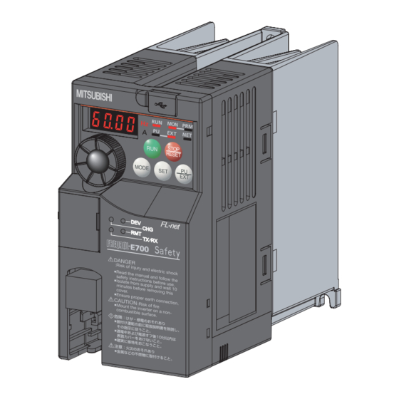
Product checking and parts identification Product checking and parts identification Unpack the inverter and check the capacity plate on the front cover and the rating plate on the inverter side face to ensure that the product agrees with your order and the inverter is intact. Inverter model FR - E720... -
Page 14: Inverter And Peripheral Devices
Inverter and peripheral devices Inverter and peripheral devices AC power supply Use within the permissible power supply Master module specifications of the inverter. To ensure safety, use a moulded case circuit breaker, earth leakage circuit breaker or magnetic contactor to switch power ON/OFF. (Refer to page 224) Moulded case circuit breaker (MCCB) or earth leakage circuit... -
Page 15: Peripheral Devices
Inverter and peripheral devices 1.2.1 Peripheral devices Check the inverter model of the inverter you purchased. Appropriate peripheral devices must be selected according to the capacity. Refer to the following list and prepare appropriate peripheral devices: Moulded Case Circuit Breaker Magnetic Contactor (MC) (MCCB) ∗1 Motor... -
Page 16: Removal And Reinstallation Of The Cover
Removal and reinstallation of the cover Removal and reinstallation of the cover 1.3.1 Front cover FR-E720-3.7KNF or lower, FR-E740-7.5KNF or lower Removal (Example of FR-E720-0.75KNF) Remove the front cover by pulling it toward you in the direction of arrow. Reinstallation (Example of FR-E720-0.75KNF) To reinstall, match the cover to the inverter front and install it straight. - Page 17 Removal and reinstallation of the cover FR-E720-5.5KNF or higher, FR-E740-11KNF or higher Removal (Example of FR-E720-5.5KNF) 1) Loosen the installation screws of the front cover 1. 2) Remove the front cover 1 by pulling it toward you in the direction of arrow. 3) Remove the front cover 2 by pulling it toward you in the direction of arrow.
-
Page 18: Wiring Cover
Removal and reinstallation of the cover 1.3.2 Wiring cover Removal and reinstallation The cover can be removed easily by pulling it toward you. To reinstall, fit the cover to the inverter along the guides. FR-E720-1.5KNF to 3.7KNF FR-E720-0.1KNF to 0.75KNF FR-E740-0.4KNF to 3.7KNF Guide Guide... -
Page 19: Installation Of The Inverter And Enclosure Design
Installation of the inverter and enclosure design Installation of the inverter and enclosure design When an inverter enclosure is to be designed and manufactured, heat generated by contained equipment, etc., the environment of an operating place, and others must be fully considered to determine the enclosure structure, size and equipment layout. - Page 20 Installation of the inverter and enclosure design Dust, dirt, oil mist Dust and dirt will cause such faults as poor contact of contact points, reduced insulation or reduced cooling effect due to moisture absorption of accumulated dust and dirt, and in-panel temperature rise due to clogged filter. In the atmosphere where conductive powder floats, dust and dirt will cause such faults as malfunction, deteriorated insulation and short circuit in a short time.
-
Page 21: Cooling System Types For Inverter Enclosure
Installation of the inverter and enclosure design 1.4.2 Cooling system types for inverter enclosure From the enclosure that contains the inverter, the heat of the inverter and other equipment (transformers, lamps, resistors, etc.) and the incoming heat such as direct sunlight must be dissipated to keep the in-panel temperature lower than the permissible temperatures of the in-panel equipment including the inverter. -
Page 22: Inverter Placement
Installation of the inverter and enclosure design 1.4.3 Inverter placement Installation of the inverter Enclosure surface mounting Remove the front cover and wiring cover to fix the inverter to the surface. FR-E720-0.1KNF to 0.75KNF FR-E720-1.5KNF or higher FR-E740-0.4KNF or higher Front cover Front cover Wiring cover... - Page 23 Installation of the inverter and enclosure design Arrangement of multiple inverters When multiple inverters are placed in the same enclosure, generally arrange them horizontally as shown in the right figure (a). When it is inevitable to arrange Inverter Inverter Inverter Inverter them vertically to minimize space, take such measures as to provide guides since heat from the bottom inverters...
-
Page 24: Wiring
WIRING This chapter describes the basic "WIRING" for use of this product. Always read the instructions before using the equipment. Wiring..................... 14 Main circuit terminal specifications ..........15 Control circuit specifications ............20 Connection of stand-alone option unit ........25... -
Page 25: Terminal Connection Diagram
Wiring Wiring 2.1.1 Terminal connection diagram Sink logic 1. DC reactor (FR-HEL) Main circuit terminal When connecting a DC reactor, remove the jumper across P1 and P/+. Control circuit terminal *2 A brake transistor is not built-in to the 0.1K Brake unit and 0.2K. -
Page 26: Main Circuit Terminal Specifications
Main circuit terminal specifications Main circuit terminal specifications 2.2.1 Specification of main circuit terminal Terminal Terminal Name Description Symbol R/L1, S/L2, AC power input Connect to the commercial power supply. T/L3 U, V, W Inverter output Connect a three-phase squirrel-cage motor. Connect a brake resistor (FR-ABR, MRS type, MYS type) across terminals P/+ and P/+, PR Brake resistor connection... - Page 27 Main circuit terminal specifications Three-phase 400V class FR-E740-0.4KNF to 3.7KNF FR-E740-5.5KNF, 7.5KNF Jumper Jumper N/- P/+ R/L1 S/L2 T/L3 R/L1 S/L2 T/L3 P/+ PR Power supply Motor Power supply Motor FR-E740-11KNF, 15KNF P/+ PR R/L1 S/L2 T/L3 Jumper Power supply Motor NOTE Make sure the power cables are connected to the R/L1, S/L2, T/L3.
-
Page 28: Cables And Wiring Length
Main circuit terminal specifications 2.2.3 Cables and wiring length Applicable cable size Select the recommended cable size to ensure that a voltage drop will be 2% or less. If the wiring distance is long between the inverter and motor, a main circuit cable voltage drop will cause the motor torque to decrease especially at the output of a low frequency. - Page 29 Main circuit terminal specifications Earthing (Grounding) precautions Always earth (ground) the motor and inverter. 1) Purpose of earthing (grounding) Generally, an electrical apparatus has an earth (ground) terminal, which must be connected to the ground before use. An electrical circuit is usually insulated by an insulating material and encased. However, it is impossible to manufacture an insulating material that can shut off a leakage current completely, and actually, a slight current flow into the case.
- Page 30 Main circuit terminal specifications Total wiring length The overall wiring length for connection of a single motor or multiple motors should be within the value in the table below. Pr. 72 PWM frequency selection 3.7K Setting 0.1K 0.2K 0.4K 0.75K 1.5K 2.2K or Higher...
-
Page 31: Control Circuit Specifications
Control circuit specifications Control circuit specifications 2.3.1 Control circuit terminal Input signal Terminal Refer to Type Terminal Name Description Rated Specifications Symbol Page Input voltage Even when the main circuit power supply is OFF, FL 24V external power 23.5 to 26.5VDC remote communication continues with the input from supply Input current... -
Page 32: Wiring Of Control Circuit
Control circuit specifications 2.3.2 Wiring of control circuit Terminal layout of control circuit terminals Recommend wire size: 0.3mm to 0.75mm +24 SD S1 S2 PC Y0 SE Wiring method Wiring For the control circuit wiring, strip off the sheath of wires, and use them with a blade terminal. For a single wire, strip off the sheath of the wire and apply directly. - Page 33 Control circuit specifications 3) Insert the wire into a socket. When using a single wire or a stranded wire without a blade terminal, push an open/close button all the way down with a flathead screw driver, and insert the wire. Open/close button Flathead screwdriver NOTE...
-
Page 34: Connecting The 24V External Power Supply
Control circuit specifications 2.3.3 Connecting the 24V external power supply FL remote communication between the master module and the inverter can be continued while the main power circuit is OFF if the 24V external power supply is connected across terminals +24 and SD. When the main circuit power supply is turned ON, the power supply changes from the 24V external power supply to the main circuit power supply. -
Page 35: Safety Stop Function
Control circuit specifications 2.3.4 Safety stop function Description of the function The terminals related to the safety stop function are shown below. Terminal Symbol Description Between S1 and PC / S2 and PC For input of safety stop channel 1. ∗1 Open: In safety stop state. -
Page 36: Connection Of Stand-Alone Option Unit
Connection of stand-alone option unit Connection of stand-alone option unit The inverter accepts a variety of stand-alone option units as required. Incorrect connection will cause inverter damage or accident. Connect and operate the option unit carefully in accordance with the corresponding option unit manual. 2.4.1 Connection of a dedicated external brake resistor (MRS type, MYS type, FR-ABR) Install a dedicated brake resistor (MRS type, MYS type, FR-ABR) outside when the motor is made to run by the load, quick... - Page 37 Connection of stand-alone option unit It is recommended to configure a sequence, which shuts off power in the input side of the inverter by the external thermal relay as shown below, to prevent overheat and burnout of the brake resistor (MRS type, MYS type) and high duty brake resistor (FR-ABR) in case the regenerative brake transistor is damaged.
-
Page 38: Connection Of The Brake Unit (Fr-Bu2)
Connection of stand-alone option unit 2.4.2 Connection of the brake unit (FR-BU2) Connect the brake unit (FR-BU2(-H)) as shown below to improve the braking capability at deceleration. If the transistors in the brake unit should become faulty, the resistor can be unusually hot. To prevent unusual overheat and fire, install a magnetic contactor on the inverter's input side to configure a circuit so that a current is shut off in case of fault. -
Page 39: Connection Of The Dc Reactor (Fr-Hel)
Connection of stand-alone option unit Connection example with the FR-BR(-H) type resistor ∗2 FR-BR MCCB Motor ∗4 R/L1 Three-phase AC S/L2 power supply T/L3 ∗3 FR-BU2 Inverter ∗1 ∗1 ∗5 ∗3 5m or less ∗1 Connect the inverter terminals (P/+ and N/-) and brake unit (FR-BU2) terminals so that their terminal names match with each other. -
Page 40: Precautions For Use Of The Inverter
PRECAUTIONS FOR USE OF THE INVERTER This chapter explains the "PRECAUTIONS FOR USE OF THE INVERTER" for use of this product. Always read the instructions before using the equipment. EMC and leakage currents ............30 Installation of power factor improving reactor ......37 Power-OFF and magnetic contactor (MC) ......... -
Page 41: Emc And Leakage Currents
EMC and leakage currents EMC and leakage currents 3.1.1 Leakage currents and countermeasures Capacitances exist between the inverter I/O cables, other cables and earth and in the motor, through which a leakage current flows. Since its value depends on the static capacitances, carrier frequency, etc., low acoustic noise operation at the increased carrier frequency of the inverter will increase the leakage current. - Page 42 EMC and leakage currents Selection of rated sensitivity current of earth (ground) leakage current breaker When using the earth leakage current breaker with the inverter circuit, select its rated sensitivity current as follows, independently of the PWM carrier frequency. Breaker designed for harmonic and Ig1, Ig2: Leakage currents in wire path during commercial surge suppression power supply operation...
-
Page 43: Emc Measures
EMC and leakage currents 3.1.2 EMC measures Some electromagnetic noises enter the inverter to malfunction it and others are radiated by the inverter to malfunction peripheral devices. Though the inverter is designed to have high immunity performance, it handles low-level signals, so it requires the following basic techniques. - Page 44 EMC and leakage currents Propagation Path Measures When devices that handle low-level signals and are liable to malfunction due to electromagnetic noises, e.g. instruments, receivers and sensors, are contained in the enclosure that contains the inverter or when their signal cables are run near the inverter, the devices may be malfunctioned by air-propagated electromagnetic noises.
-
Page 45: Power Supply Harmonics
EMC and leakage currents 3.1.3 Power supply harmonics The inverter may generate power supply harmonics from its converter circuit to affect the power generator, power capacitor etc. Power supply harmonics are different from noise and leakage currents in source, frequency band and transmission path. Take the following countermeasure suppression techniques. -
Page 46: Harmonic Suppression Guideline In Japan
EMC and leakage currents 3.1.4 Harmonic suppression guideline in Japan Harmonic currents flow from the inverter to a power receiving point via a power transformer. The harmonic suppression guideline was established to protect other consumers from these outgoing harmonic currents. The three-phase 200V input specifications 3.7kW or less are previously covered by "Harmonic suppression guideline for household appliances and general-purpose products"... - Page 47 EMC and leakage currents 1) Calculation of equivalent capacity (P0) of harmonic generating equipment The "equivalent capacity" is the capacity of a 6-pulse converter converted from the capacity of consumer's harmonic generating equipment and is calculated with the following equation. If the sum of equivalent capacities is higher than the limit in Table 3, harmonics must be calculated with the following procedure: P0 = Σ(Ki Pi) [kVA]...
-
Page 48: Installation Of Power Factor Improving Reactor
Installation of power factor improving reactor Installation of power factor improving reactor When the inverter is connected near a large-capacity power transformer (500kVA or more) or when a power capacitor is to be switched over, an excessive peak current may flow in the power input circuit, damaging the converter circuit. To prevent this, always install an optional reactor (FR-HAL, FR-HEL). -
Page 49: Power-Off And Magnetic Contactor (Mc)
Power-OFF and magnetic contactor (MC) Power-OFF and magnetic contactor (MC) Inverter input side magnetic contactor (MC) On the inverter input side, it is recommended to provide an MC for the following purposes. (Refer to page 4 for selection.) 1) To release the inverter from the power supply when the fault occurs or when the drive is not functioning (e.g. emergency stop operation). -
Page 50: Inverter-Driven 400V Class Motor
Inverter-driven 400V class motor Inverter-driven 400V class motor In the PWM type inverter, a surge voltage attributable to wiring constants is generated at the motor terminals. Especially for a 400V class motor, the surge voltage may deteriorate the insulation. When the 400V class motor is driven by the inverter, consider the following measures: Measures It is recommended to take either of the following measures:... -
Page 51: Precautions For Use Of The Inverter
Precautions for use of the inverter Precautions for use of the inverter The FR-E700 series is a highly reliable product, but incorrect peripheral circuit making or operation/handling method may shorten the product life or damage the product. Before starting operation, always recheck the following items. (1) Use crimping terminals with insulation sleeve to wire the power supply and motor. - Page 52 Precautions for use of the inverter (12) Across P/+ and PR terminals, connect only an external regenerative brake discharging resistor. Do not connect a mechanical brake. The brake resistor cannot be connected to the 0.1K or 0.2K. Leave terminals P/+ and PR open. Also, never short between these terminals.
-
Page 53: Failsafe Of The System Which Uses The Inverter
Failsafe of the system which uses the inverter Failsafe of the system which uses the inverter When a fault occurs, the inverter trips to output a fault signal. However, a fault output signal may not be output at an inverter fault occurrence when the detection circuit or output circuit fails, etc. - Page 54 Failsafe of the system which uses the inverter 4)Checking the motor operating status by the start signal input to the inverter and inverter output current detection signal. The output current detection signal (Y12 signal) is output when the inverter operates and currents flows in the motor. Check if Y12 signal is output when inputting the start signal to the inverter (forward signal is STF signal and reverse signal is STR signal).
- Page 55 MEMO...
- Page 56 FL REMOTE COMMUNICATION FUNCTION This chapter explains the "FL REMOTE COMMUNICATION FUNCTION" for use of this product. Always read the instructions before using the equipment. FL remote communication specification ........46 Node address setting ..............46 Wiring.................... 47 LED status ..................49 Operation mode setting...............
-
Page 57: Fl Remote Communication Specification
FL remote communication specification FL remote communication specification Type Built-in to an inverter, RJ-45 connector connection method Power supply Supplied from the inverter or the 24V external power supply Connection cable FL-net dedicated cable (Refer to page 47) Maximum number of 64 units maximum connectable inverters Communication speed... -
Page 58: Wiring
Wiring Wiring 4.3.1 Connecting to the network (1) Be sure to check the following points before connecting the inverter to the network. Check that the correct node address is set. (Refer to page 46) Check that the FL-net dedicated cable is correctly connected to the FL remote communication connector. (Refer to page 48) (2) System configuration Segment 1 Personal computer... -
Page 59: Connecting The Fl-Net Dedicated Cable
Wiring 4.3.4 Connecting the FL-net dedicated cable Connect the FL-net dedicated cable to the FL remote communication connector. NOTE Do not connect the FL-net dedicated cable to the terminal reserved for manufacturer settings. FL remote communication connector Terminal reserved for manufacturer settings CAUTION Do not connect a parameter unit (FR-PU07, etc.) to the FL remote communication connector. -
Page 60: Led Status
LED status LED status Each LED indicates the operating status of the inverter and network according to the indication status. TX RX : Communication set status LED : Device status LED TX/RX : Reception/transmission LED : Remote status LED 4.4.1 Device status LED (DEV), remote status LED (RMT) LED Status Node Status... -
Page 61: Operation Mode Setting
Operation mode setting Operation mode setting 4.5.1 Operation mode basics The operation mode specifies the source of the start command and the frequency command for the inverter. Basically, there are following operation modes. Network operation mode (NET operation mode): For inputting a start command and a frequency command through FL remote communication. -
Page 62: Pu Operation Interlock
Operation mode setting 4.5.2 PU operation interlock The PU operation interlock function is designed to forcibly change the operation mode to the Network operation mode when the PU operation interlock signal (X12) input turns OFF. This function prevents the operation mode from being accidentally unswitched from the PU operation mode. If the operation mode is left unswitched from the PU operation mode, the inverter does not reply to the commands sent through FL remote communication. -
Page 63: Overview Of Fl Remote Communication
FL remote communication FL remote communication 4.6.1 Overview of FL remote communication Output from the inverter to the network Main items to be output from the inverter to the network and their descriptions are explained below. ( : with function, ×: without function) Cyclic Message Refer to... -
Page 64: Cyclic Transmission
Cyclic transmission Cyclic transmission Cyclic transmission transmits data periodically. Each node shares data through common memory. Data of I/O area is updated periodically by cyclic transmission. The master controls the inverter by setting run command (control input command, set frequency, etc.) in the output data area. -
Page 65: Common Memory
Cyclic transmission 4.7.1 Common memory Concept of common memory is stated below. The common memory is used as a shared memory between nodes which perform cyclic transmission. The common memory has two areas which are "common memory area 1" and "common memory area 2". Common memory area 1 is I/O data area. - Page 66 Cyclic transmission Common memory area 1 Refer to Size Description Page Input data 256 words Data to be sent from inverter to master (4 words). (Inverter→master) (512 bytes) The data includes inverter status, output frequency, etc. Output data 256 words Data to be sent from master to inverter (4 words).
-
Page 67
Cyclic transmission (1) Control information (inverter→master)
Value Slave status FL remote network is not connected FL remote network remote at a stop FL remote network remote connection processing FL remote network remote operating Master is not present Own node is disconnected Setting error ... -
Page 68: Output Data (Master To Inverter)
Cyclic transmission 4.7.2 Output data (master to inverter) [Master output area (master → inverter)] Address (word boundary) Applications Word (n: node address) 4(n-1)+256 (1) Control input command 4(n-1)+257 — (not used) 4(n-1)+258 (2) Set frequency (0.01 Hz increments) 4(n-1)+259 — (not used) Control input command Set control input command such as forward and reverse rotation commands. - Page 69 Cyclic transmission Set frequency The set frequency can be set in 0.01Hz increments. Range Unit 0 to 15 0.00Hz to 400.00Hz 0.01Hz Example: If you want to set 120.00Hz, set 12000, which is the value multiplied by 100. REMARKS Regardless of the Pr.37 setting, the value is always set in frequency (Hz).
-
Page 70: Input Data (Inverter To Master)
Cyclic transmission 4.7.3 Input data (inverter to master) [Master input area (inverter → master)] Address (word boundary) Applications Word (n: node address) 4(n-1)+0 (1) Inverter status monitor 4(n-1)+1 (3) Life/alarm (2) Alarm code 4(n-1)+2 (4) Output frequency monitor 4(n-1)+3 (5) Output current monitor Inverter status monitor Monitors the output signal of the inverter from the network. - Page 71 Cyclic transmission Life/alarm Whether the control circuit capacitor, main circuit capacitor, cooling fan, and each parts of the inrush current limit circuit have reached the life alarm output level or not can be checked. Name Description 0: without alarm, 1: with alarm The control circuit capacitor life is calculated from the energization time and temperature Control circuit capacitor life according to the operating status, and is counted down from 100%.
-
Page 72: Message Transmission
Message transmission Message transmission Message transmission is a non-periodic data communication method to communicate to a specified node when send request is given. Basic function of message transmission is as follows. (1) When a node receives a token, one frame can be sent before sending cyclic frame. (2) The message frame size which can be sent at a time is 1024 bytes at maximum. -
Page 73: Word Block Read/Write
Read Write boundary) boundary) boundary) × H10000000 Manufacturer name: MITSUBISHI ELECTRIC CORPORATION × H10000064 Product name: FR-E700 × H1000008C Inverter capacity : in 0.1kW increments ∗ When accessing a message, the access size should be the size stated in the table above. -
Page 74
Message transmission
Item Data Portion Request Not applicable Returns "MITSUBISHI ELECTRIC CORPORATION". The rest are the characters for space. Offset Bit15 to Bit8 Bit7 to Bit0 Normal Second character First character response Fourth character Third character... -
Page 75
Message transmission Inverter status Monitors the output signal of the inverter from network. Message Applications Virtual address Access (byte boundary) Address Size Description Read Write (word boundary) (word boundary) × H100000DC Inverter status ∗ When accessing a message, the access size should be the size stated in the table above.
... - Page 76 Message transmission Inverter monitor value of each monitor is as in the table below. (When accessing a message, the access size should be 2 bytes (1 word).) Code number Description Unit Code number Description Unit H100001A6 Converter output voltage peak value 0.1V H10000190 Output frequency...
- Page 77 Message transmission Fault record Fault history can be monitored up to eight past faults occurred in the inverter. Message Applications Virtual address Access (byte boundary) Address Size Description Read Write (word boundary) (word boundary) × H10001770 3000 Fault record all clear ×...
-
Page 78
Message transmission
Item Data Portion Request Not applicable Output frequency, output current, output voltage, and energization time at fault occurrence is returned. -
Page 79: Network Parameter Read
Message transmission 4.8.3 Network parameter read With this function, network parameter information of other node is read from network. Item Data Portion Request Not applicable Offset Bit15 to Bit8 Bit7 to Bit0 Remarks Second character First character Node name Fourth character Third character Character string of "FR-E700"... -
Page 80: Log Data Read
Message transmission 4.8.4 Log data read With this function, log information of other node is read from network. Item Data Portion Request Not applicable Offset Bit7 to Bit0 Offset Bit7 to Bit0 +152 to +164 — The number of communication socket The number of message transmission transmitting times +168... -
Page 81: Profile Read
Message transmission 4.8.6 Profile read With this function, system parameter of device profile of other node is read from network. Item Data Portion Request Not applicable Offset Bit15 to Bit0 Normal response Read data (see the table below for details) Response Error Offset... -
Page 82: Message Loopback
Message transmission Arrangement of transfer syntax data (coded) Identifier Length Description 81AA Identifier Length Description Identifier Length Description "COMVER" "ID" "SYSPARA" "REV" "REVDATE" Identifier Length Description Identifier Length Description 07D9 Identifier Length Description "DVCATEGORY" "INV" "VENDOR" "MELCO " "DVMODEL" "FR-A7NF " Identifier Length Description... - Page 83 MEMO...
-
Page 84: Parameters
PARAMETERS This chapter explains the "PARAMETERS" for use of this product. Always read the instructions before using the equipment. The following marks are used to indicate the controls as below..V/F control ..Advanced magnetic flux vector control AD MFVC AD MFVC AD MFVC ..General-purpose magnetic flux vector control GP MFVC... -
Page 85: Operation Panel
Operation panel Operation panel 5.1.1 Names and functions of the operation panel The operation panel cannot be removed from the inverter. Operating status indicator Operation mode indicator Lit or flicker during inverter operation. ∗ PU: Lit to indicate PU operation mode. EXT: Not lit. -
Page 86: Basic Operation (Factory Setting)
Operation panel 5.1.2 Basic operation (factory setting) Operation mode switchover At power-ON (Network operation mode)* PU Jog operation mode (Example) PU operation mode Value change and frequency flicker. (output frequency monitor) Frequency setting has been written and completed!! STOP Output current monitor Output voltage monitor Display the (Refer to page 76) -
Page 87: Changing The Parameter Setting Value
Operation panel 5.1.3 Changing the parameter setting value Changing Change the Pr. 1 Maximum frequency setting. example Operation Display Screen at power-ON The inverter starts up in the Network operation mode. The monitor display appears. Change the X12 signal (Bit11) setting to "1." X12 signal (Bit11) gives a control input command through FL remote communication. -
Page 88: Setting Dial Push
Operation panel 5.1.4 Setting dial push Push the setting dial ( ) to display the set frequency* currently set. ∗ Appears when PU operation mode is selected. -
Page 89: Parameter List
Parameter list Parameter list Parameter list 5.2.1 Parameter list For simple variable-speed operation of the inverter, the initial setting of the parameters may be used as they are. Set the necessary parameters to meet the load and operational specifications. Parameter setting, change and check are available from the operation panel. - Page 90 Parameter list Parameter list Control Mode-based Minimum Refer Parameter Func- Initial Customer Correspondence Table Parameter Name Setting Range Setting Parameter tion Value Setting Increments Page Clear All clear AD MFVC AD MFVC AD MFVC GP MFVC GP MFVC GP MFVC 136, —...
- Page 91 Parameter list Parameter list Control Mode-based Minimum Refer Parameter Func- Initial Customer Correspondence Table Parameter Name Setting Range Setting Parameter tion Value Setting Increments Page Clear All clear AD MFVC AD MFVC AD MFVC GP MFVC GP MFVC GP MFVC 93, 95, ×...
- Page 92 Parameter list Parameter list Control Mode-based Minimum Refer Parameter Func- Initial Customer Correspondence Table Parameter Name Setting Range Setting Parameter tion Value Setting Increments Page Clear All clear AD MFVC AD MFVC AD MFVC GP MFVC GP MFVC GP MFVC Automatic restart after instantaneous 0, 1, 10, 11 power failure selection...
- Page 93 Parameter list Parameter list Control Mode-based Minimum Refer Parameter Func- Initial Customer Correspondence Table Parameter Name Setting Range Setting Parameter tion Value Setting Increments Page Clear All clear AD MFVC AD MFVC AD MFVC GP MFVC GP MFVC GP MFVC Stop-on contact excitation current low- ×...
- Page 94 Parameter list Parameter list Control Mode-based Minimum Refer Parameter Func- Initial Customer Correspondence Table Parameter Name Setting Range Setting Parameter tion Value Setting Increments Page Clear All clear AD MFVC AD MFVC AD MFVC GP MFVC GP MFVC GP MFVC —...
-
Page 95: Control Mode
Parameters according to purposes Control mode 5.3.1 Changing the control method (Pr. 80, Pr. 81, Pr. 800) ..............93 Adjustment of the output torque (current) of the motor 5.4.1 Manual torque boost (Pr. 0, Pr. 46) ....................94 5.4.2 Advanced magnetic flux vector control (Pr. 71, Pr. 80, Pr. 81, Pr.89, Pr. 800) ......95 5.4.3 General-purpose magnetic flux vector control (Pr. - Page 96 5.12 Monitor display and monitor output signal 5.12.1 Speed display and speed setting (Pr. 37)................... 146 5.12.2 Monitor display selection of the operation panel (Pr. 52, Pr. 170, Pr. 171, Pr. 268, Pr. 563, Pr. 564)..............147 5.13 Operation selection at power failure and instantaneous power failure 5.13.1 Automatic restart after instantaneous power failure/flying start...
- Page 97 Control mode Control mode V/F control (initial setting), Advanced magnetic flux vector control and General-purpose magnetic flux vector control are available with this inverter. V/F Control It controls frequency and voltage so that the ratio of frequency (F) to voltage (V) is constant when changing frequency. Advanced (General-purpose) magnetic flux vector control This control divides the inverter output current into an excitation current and a torque current by vector calculation and makes voltage compensation to flow a motor current which meets the load torque.
-
Page 98: Changing The Control Method (Pr. 80, Pr. 81, Pr. 800)
Control mode 5.3.1 Changing the control method (Pr. 80, Pr. 81, Pr. 800) Set when selecting the control method for Advanced magnetic flux vector control and General-purpose magnetic flux vector control. The initial value is V/F control. Select a control mode using Pr. 800 Control method selection. Parameter Initial Name... -
Page 99: Adjustment Of The Output Torque (Current) Of The Motor
Adjustment of the output torque (current) of the motor Adjustment of the output torque (current) of the motor Purpose Parameter that should be Set Refer to Page Set starting torque manually Manual torque boost Pr. 0, Pr. 46 Advanced magnetic flux vector Automatically control output current Pr. -
Page 100: Advanced Magnetic Flux Vector Control (Pr. 71, Pr. 80, Pr. 81, Pr.89, Pr. 800)
Adjustment of the output torque (current) of the motor 5.4.2 Advanced magnetic flux vector control (Pr. 71, Pr. 80, Pr. 81, Pr.89, Pr. 800) AD MFVC AD MFVC AD MFVC Advanced magnetic flux vector control can be selected by setting the capacity, poles and type of the motor used in Pr. 80 and Pr. -
Page 101
Adjustment of the output torque (current) of the motor
Perform secure wiring. (Refer to page 14) Set the motor. (Pr. 71) Pr. 71 Setting ∗1 Motor Remarks Mitsubishi standard SF-JR 0 (initial value) motor SF-HR Mitsubishi high... - Page 102 Adjustment of the output torque (current) of the motor Adjust the motor speed fluctuation at load fluctuation (Pr. 89 Speed control gain (Advanced magnetic flux vector)) The motor speed fluctuation at load fluctuation can be adjusted using Pr. 89. (It is useful when the speed command does not match the motor speed after the FR-E500 series inverter is replaced with the FR-E700 series inverter, etc.) Speed...
-
Page 103: General-Purpose Magnetic Flux Vector Control (Pr. 71, Pr. 80, Pr. 81, Pr. 800)
Adjustment of the output torque (current) of the motor 5.4.3 General-purpose magnetic flux vector control (Pr. 71, Pr. 80, Pr. 81, Pr. 800) GP MFVC GP MFVC GP MFVC General-purpose magnetic flux vector control is the same function as the FR-E500 series. Select this control when the same operation characteristic is necessary. -
Page 104
Adjustment of the output torque (current) of the motor
Perform secure wiring. (Refer to page 14) Set the motor.(Pr. 71) Pr. 71 Setting ∗1 Motor Remarks Mitsubishi standard SF-JR 0 (initial value) motor SF-HR Mitsubishi high... -
Page 105: Slip Compensation (Pr. 245 To Pr. 247)
Adjustment of the output torque (current) of the motor 5.4.4 Slip compensation (Pr. 245 to Pr. 247) GP MFVC GP MFVC GP MFVC When V/F control or General-purpose magnetic flux vector control is performed, the inverter output current may be used to assume motor slip to keep the motor speed constant. -
Page 106: Stall Prevention Operation (Pr. 22, Pr. 23, Pr. 48, Pr. 66, Pr. 156, Pr. 157, Pr. 277)
Adjustment of the output torque (current) of the motor 5.4.5 Stall prevention operation (Pr. 22, Pr. 23, Pr. 48, Pr. 66, Pr. 156, Pr. 157, Pr. 277) This function monitors the output current and automatically changes the output frequency to prevent the inverter from coming to trip due to overcurrent, overvoltage, etc. - Page 107 Adjustment of the output torque (current) of the motor Setting of stall prevention operation level (Pr. 22) Pr. 22 Set in the percentage of the output current to the rated inverter current at which stall prevention operation will be Output current performed.
- Page 108 Adjustment of the output torque (current) of the motor Setting of stall prevention operation in high frequency range (Pr. 22, Pr. 23, Pr. 66) (Pr. 22 = 150%, Pr. 23 = 100%, Pr. 66 = 60Hz) Setting example Pr. 22 When Pr.
- Page 109 Adjustment of the output torque (current) of the motor Limit the stall prevention operation and fast-response current limit operation according to the operating status (Pr. 156) Refer to the following table and select whether stall prevention operation and fast-response current limit operation will be performed or not and the operation to be performed at OL signal output.
-
Page 110: Limiting The Output Frequency
Limiting the output frequency Limiting the output frequency Purpose Parameter that should be Set Refer to Page Set upper limit and lower limit of Maximum/minimum Pr. 1, Pr. 2, Pr. 18 output frequency frequency Perform operation by avoiding Frequency jump Pr. -
Page 111: Avoiding Mechanical Resonance Points (Frequency Jumps) (Pr. 31 To Pr. 36)
Limiting the output frequency 5.5.2 Avoiding mechanical resonance points (frequency jumps) (Pr. 31 to Pr. 36) When avoiding resonance arisen from the natural frequency of a mechanical system, use these parameters to jump the resonant frequencies. Parameter Name Initial Value Setting Range Description Number... -
Page 112: V/F Pattern
V/F pattern V/F pattern Purpose Parameter that should be Set Refer to Page Base frequency, Set motor ratings Pr. 3, Pr. 19, Pr. 47 Base frequency voltage Select a V/F pattern according to Load pattern selection Pr. 14 applications. 5.6.1 Base frequency, voltage (Pr. - Page 113 V/F pattern Base frequency voltage setting (Pr. 19) Use Pr. 19 Base frequency voltage to set the base voltage (e.g. rated motor voltage). If the setting is less than the power supply voltage, the maximum output voltage of the inverter is as set in Pr. 19. Pr.
-
Page 114: Load Pattern Selection (Pr. 14)
V/F pattern 5.6.2 Load pattern selection (Pr. 14) You can select the optimum output characteristic (V/F characteristic) for the application and load characteristics. Parameter Name Initial Value Setting Range Description Number For constant-torque load For variable torque load For constant-torque elevators Load pattern selection (at reverse rotation boost of 0%) For constant-torque elevators... - Page 115 V/F pattern REMARKS When torque is continuously regenerated as vertical lift load, it is effective to set the rated voltage in Pr. 19 Base frequency voltage to prevent trip due to current at regeneration. In addition, when the RT signal is ON, the other second functions are also valid. NOTE Load pattern selection does not function under Advanced magnetic flux vector control and General-purpose magnetic flux vector control.
-
Page 116: Frequency Setting By Input Signals
Frequency setting by input signals Frequency setting by input signals Purpose Parameter that should be Set Refer to Page Make frequency setting by Multi-speed operation Pr. 4 to Pr. 6, Pr. 24 to Pr. 27 combination of input signals Infinitely variable speed setting by Remote setting function Pr. - Page 117 Frequency setting by input signals Multi-speed setting for 4 or more speeds (Pr. 24 to Pr. 27) Frequency from speed 4 to speed 7 can be set according to the combination of the RH, RM and RL signals. Set the running frequencies Speed 5 in Pr.
-
Page 118: Remote Setting Function (Pr. 59)
Frequency setting by input signals 5.7.2 Remote setting function (Pr. 59) Continuous variable-speed operation can be performed using acceleration and deceleration signals. By simply setting this parameter, you can use the acceleration, deceleration and setting clear functions of the motorized speed setter (FR-FK). Description Parameter Setting... - Page 119 Frequency setting by input signals NOTE The range of frequency changeable by RH (acceleration) and RM (deceleration) is 0 to The set frequency is clamped (Hz) at (main speed + Pr. 1) maximum frequency (Pr. 1 or Pr. 18 setting). Note that the maximum value of set frequency Output frequency is Set frequency...
- Page 120 Frequency setting by input signals REMARKS During Jog operation, the remote setting function is invalid. Setting frequency is "0" Even when remotely-set frequency is cleared by turning ON the RL (clear) signal after turn Remotely-set frequency stored last time OFF (ON) of both the RH and RM Within 1 minute signals, the inverter operates at Remotely-set frequency...
-
Page 121: Setting Of Acceleration/Deceleration Time And Acceleration/ Deceleration Pattern
Setting of acceleration/deceleration time and acceleration/ deceleration pattern Setting of acceleration/deceleration time and acceleration/ deceleration pattern Purpose Parameter that should be Set Refer to Page Motor acceleration/deceleration Acceleration/deceleration Pr. 7, Pr. 8, Pr. 20, Pr. 21, Pr. 44, time setting times Pr. - Page 122 Setting of acceleration/deceleration time and acceleration/ deceleration pattern Acceleration time setting (Pr. 7, Pr. 20) Use Pr. 7 Acceleration time to set the acceleration time required to reach Pr. 20 Pr. 20 Running (60Hz) Acceleration/deceleration reference frequency from 0Hz. frequency Set the acceleration time according to the following formula.
- Page 123 Setting of acceleration/deceleration time and acceleration/ deceleration pattern Set two kinds of acceleration/deceleration times (RT signal, Pr. 44, Pr. 45, Pr. 147 ) Pr. 44 and Pr. 45 are valid when the RT signal is ON, or the output frequency reaches or exceeds the setting of Pr. 147. When "9999"...
-
Page 124: Starting Frequency And Start-Time Hold Function (Pr. 13, Pr. 571)
Setting of acceleration/deceleration time and acceleration/ deceleration pattern 5.8.2 Starting frequency and start-time hold function (Pr. 13, Pr. 571) You can set the starting frequency and hold the set starting frequency for a certain period of time. Set these functions when you need the starting torque or want to smooth motor drive at a start. Parameter Name Initial Value... -
Page 125: Acceleration/Deceleration Pattern (Pr. 29)
Setting of acceleration/deceleration time and acceleration/ deceleration pattern 5.8.3 Acceleration/deceleration pattern (Pr. 29) You can set the acceleration/deceleration pattern suitable for application. Parameter Name Initial Value Setting Range Description Number Linear acceleration/ deceleration Acceleration/deceleration S-pattern acceleration/deceleration A pattern selection S-pattern acceleration/deceleration B The above parameters can be set when Pr. -
Page 126: Shortest Acceleration/Deceleration (Automatic Acceleration/Deceleration)
Setting of acceleration/deceleration time and acceleration/ deceleration pattern 5.8.4 Shortest acceleration/deceleration (automatic acceleration/deceleration) (Pr. 61 to Pr. 63, Pr. 292, Pr. 293) The inverter operates in the same conditions as when appropriate values are set in each parameter even if acceleration/deceleration time and V/F pattern are not set. - Page 127 Setting of acceleration/deceleration time and acceleration/ deceleration pattern Adjustment of shortest acceleration/deceleration mode (Pr. 61 to Pr. 63) By setting the adjustment parameters Pr. 61 and Pr. 63, the application range can be made wider. Parameter Name Setting Range Description Number For example, when the motor and inverter are different in capacity, set the rated motor current value.
-
Page 128: Selection And Protection Of A Motor
Selection and protection of a motor Selection and protection of a motor Purpose Parameter that should be Set Refer to Page Motor protection from overheat Electronic thermal O/L relay Pr. 9, Pr. 51 Use the constant-torque motor Applied motor Pr. 71 The motor performance can be Pr. - Page 129 Selection and protection of a motor Set two different electronic thermal O/L relays (Pr. 51) Use this function when running two motors of different rated currents individually by a single inverter. (When running two motors together, use external thermal relays.) Set the rated current of the second motor to Pr.
-
Page 130: Applied Motor (Pr. 71, Pr. 450)
Selection and protection of a motor 5.9.2 Applied motor (Pr. 71, Pr. 450) Setting of the used motor selects the thermal characteristic appropriate for the motor. Setting is required to use a constant-torque motor. Thermal characteristic of the electronic thermal relay function suitable for the motor is set. - Page 131 Selection and protection of a motor Use two motors (Pr. 450) Set Pr. 450 Second applied motor to use two different motors with one inverter. When "9999" (initial value) is set, no function is selected. When a value other than 9999 is set in Pr. 450, the second motor is valid when the RT signal turns ON. REMARKS The RT signal acts as the second function selection signal and makes the other second functions valid.
-
Page 132: Exhibiting The Best Performance For The Motor (Offline Auto Tuning) (Pr. 71, Pr. 80 To Pr. 84, Pr. 90 To Pr. 94, Pr. 96, Pr. 859)
Selection and protection of a motor 5.9.3 Exhibiting the best performance for the motor (offline auto tuning) (Pr. 71, Pr. 80 to Pr. 84, Pr. 90 to Pr. 94, Pr. 96, Pr. 859) The motor performance can be maximized with offline auto tuning. What is offline auto tuning? When performing Advanced magnetic flux vector control or General-purpose magnetic flux vector control, the motor can be run with the optimum operating characteristics by automatically measuring the motor constants (offline auto... - Page 133 Selection and protection of a motor The setting range and increments of Pr. 82, Pr. 90 to Pr. 94 and Pr. 859 changes according to the setting value of Pr. 71 and Pr. 96. Auto Tuning Measured Value Internal Stored Value ∗1 Direct Input Value ∗2 Applied Motor ∗3...
- Page 134 Selection and protection of a motor Setting 1) Select Advanced magnetic flux vector control (Refer to page 95) or General-purpose magnetic flux vector control (Refer to page 98). 2) Set "1" or "11" in Pr. 96 Auto tuning setting/status. When the setting is "1" ..Tune all motor constants without running the motor. When performing Advanced magnetic flux vector control, set "1"...
- Page 135 Selection and protection of a motor Execution of tuning POINT Before performing tuning, check the monitor display of the operation panel if the inverter is in the status for tuning. (Refer to 3) below.) When the start command is turned ON under V/F control, the motor starts. 1) Set "1"...
- Page 136 Selection and protection of a motor 4) When offline auto tuning ends, press on the operation panel. This operation resets the offline auto tuning, and the monitor display of the operation panel returns to normal. 5) Set "0" in the X12 signal (Bit11), which gives a control input command through FL remote communication. Then, change the operation mode to Network operation mode.
-
Page 137
Selection and protection of a motor Utilizing or changing offline auto tuning data for use The data measured in the offline auto tuning can be read and utilized or changed.
1) Set Pr. 71 according to the motor used. Pr. - Page 138 Selection and protection of a motor Method to set the motor constants without using the offline auto tuning data The Pr. 90 to Pr. 94 motor constants may either be entered in [Ω] or in [mH]. Before starting operation, confirm which motor constant unit is used.
-
Page 139
Selection and protection of a motor To enter the Pr. 90 to Pr. 94 motor constants in [mH]
1) Set Pr. 71 according to the motor used. Pr.71 Setting ∗1 Motor Mitsubishi standard motor SF-JR Mitsubishi high efficiency motor SF-HR SF-JRCA 4P Mitsubishi constant-torque motor... -
Page 140: 5.10 Motor Brake And Stop Operation
Motor brake and stop operation 5.10 Motor brake and stop operation Purpose Parameter that should be Set Refer to Page Motor braking torque adjustment DC Injection brake Pr. 10 to Pr. 12 Improve the motor braking torque with Selection of a Pr. -
Page 141: Selection Of A Regenerative Brake (Pr. 30, Pr. 70)
Motor brake and stop operation CAUTION As stop holding torque is not produced, install a mechanical brake. Parameters referred to Pr. 13 Starting frequency Refer to page 119 Pr. 71 Applied motor Refer to page 125 5.10.2 Selection of a regenerative brake (Pr. 30, Pr. 70) When making frequent starts/stops, use the optional brake resistor (MRS type, MYS type), high-duty brake resistor (FR-ABR) and brake unit (FR-BU2) to increase the regenerative brake duty. - Page 142 Motor brake and stop operation Regenerative brake duty alarm output 100%: regenerative overvoltage protection operation value [RB] appears on the operation panel when 85% of the Ratio of the brake duty to the Pr. 70 regenerative brake duty set in Pr. 70 is reached. If the setting (%) regenerative brake duty reaches 100% of the Pr.
-
Page 143: Stop Selection (Pr. 250)
Motor brake and stop operation 5.10.3 Stop selection (Pr. 250) Used to select the stopping method (deceleration to a stop or coasting) when the start signal turns OFF. Used to stop the motor with a mechanical brake, etc. together with switching OFF of the start signal. Parameter Initial Name... -
Page 144: Stop-On Contact Control Function (Pr. 6, Pr. 48, Pr. 270, Pr. 275, Pr. 276)
Motor brake and stop operation 5.10.4 Stop-on contact control function (Pr. 6, Pr. 48, Pr. 270, Pr. 275, Pr. 276) AD MFVC AD MFVC AD MFVC GP MFVC GP MFVC GP MFVC To ensure accurate positioning at the upper limit etc. of a... - Page 145 Motor brake and stop operation Function switching of stop-on-contact control selection Normal Operation With stop-on-contact Control Main Functions (either RL or RT is OFF or both are OFF) (both RL and RT are ON) Output frequency Multi-speed, setting frequency (Refer to page 58) Pr.
-
Page 146: 5.11 I/O Signal Control
I/O signal control 5.11 I/O signal control Purpose Parameter that should be Set Refer to Page Operation of start signals (STF, STR — signal) Reset cancellation and inverter run — detection Second function selection signal — (RT signal) Setting MRS signal (output shutoff) MRS input selection Pr. -
Page 147: Reset Cancel Signal (Ready Signal) And Inverter Running Signal (Run Signal)
I/O signal control 5.11.2 Reset cancel signal (READY signal) and inverter running signal (RUN signal) Power supply DC injection brake operation point DC injection brake operation Pr. 13 Starting frequency Time Reset processing READY When the reset operation of the inverter is canceled, reset cancel signal (READY) is output. When the output frequency of the inverter rises to or above Pr. -
Page 148: Second Function Selection Signal (Rt Signal)
I/O signal control 5.11.3 Second function selection signal (RT signal) Second acceleration/deceleration time When the RT signal turns ON, the second function becomes valid. The second function has the following applications. (a) Switching between normal use and emergency use (b) Switching between heavy load and light load (c) Changing of acceleration/deceleration time by broken line acceleration/deceleration (d) Switching of characteristic between the main motor and sub... -
Page 149: Detection Of Output Frequency (Su, Fu Signal, Pr. 41 To Pr. 43)
I/O signal control 5.11.5 Detection of output frequency (SU, FU signal, Pr. 41 to Pr. 43) The inverter's output frequency is detected, and the signals are output through FL remote communication. Parameter Name Initial Value Setting Range Description Number Up-to-frequency 0 to 100% Level where the SU signal turns ON. -
Page 150: Output Current Detection Function (Y12 Signal, Y13 Signal, Pr. 150 To Pr. 153)
I/O signal control 5.11.6 Output current detection function (Y12 signal, Y13 signal, Pr. 150 to Pr. 153) The output current is detected while the inverter is running, and the signals are output through FL remote communication. Parameter Setting Name Initial Value Description Number Range... -
Page 151: 5.12 Monitor Display And Monitor Output Signal
Monitor display and monitor output signal 5.12 Monitor display and monitor output signal Refer to Purpose Parameter that should be Set Page Display motor speed Speed display and speed setting Pr. 37 Set speed Operation panel main display Change the monitored item Pr. -
Page 152: Monitor Display Selection Of The Operation Panel (Pr. 52, Pr. 170, Pr. 171, Pr. 268, Pr. 563, Pr. 564)
Monitor display and monitor output signal 5.12.2 Monitor display selection of the operation panel (Pr. 52, Pr. 170, Pr. 171, Pr. 268, Pr. 563, Pr. 564) The monitor to be displayed on the main screen of the operation panel can be selected. Parameter Name Initial Value... - Page 153 Monitor display and monitor output signal Monitored Item Unit Pr. 52 Setting Description Adds up and displays the power amount based on the output power monitor. Cumulative power ∗3 0.01kWh ∗5 Can be cleared by Pr. 170. (Refer to page 149) Displays the ON/OFF statuses of the inverter output terminals and FL remote Inverter output terminal —...
- Page 154 Monitor display and monitor output signal Operation panel I/O terminal monitor (Pr. 52) When Pr.52 = "55," statuses of the output terminals and FL remote communication virtual terminals (FU, ALM signal) are monitored on the operation panel. The I/O terminal monitor is displayed on the third monitor. The LEDs are ON when a signal is input to terminal Y0 and when the signals FU and ALM are input.
- Page 155 Monitor display and monitor output signal Selecting the decimal digits for the monitor (Pr. 268) As the operation panel display is 4 digits long, the decimal places may vary at analog input, etc. The decimal places can be hidden by selecting the decimal digits. In such a case, the decimal digits can be selected by Pr.
-
Page 156: Operation Selection At Power Failure And Instantaneous Power Failure
Operation selection at power failure and instantaneous power failure 5.13 Operation selection at power failure and instantaneous power failure Purpose Parameter that should be Set Refer to Page At instantaneous power failure Automatic restart operation Pr. 57, Pr. 58, Pr. 96, occurrence, restart inverter without after instantaneous power Pr. - Page 157 Operation selection at power failure and instantaneous power failure When Pr. 162 = 1, 11 (without frequency search) Automatic restart operation selection (Pr. 162, Pr. 299) Instantaneous (power failure) time Without frequency search Power supply When Pr. 162 = "1 (initial value) " or "11", automatic restart (R/L1, S/L2, T/L3) operation is performed in a reduced voltage system, where the voltage is gradually risen with the output...
- Page 158 Operation selection at power failure and instantaneous power failure Restart coasting time (Pr. 57) Coasting time is the time from when the motor speed is detected until automatic restart control is started. Set Pr. 57 to "0" to perform automatic restart operation. The coasting time is automatically set to the value below.
- Page 159 Operation selection at power failure and instantaneous power failure Setting 1) Set "21" in Pr. 96 Auto tuning setting/status. Tuning is performed without motor running. It takes approximately 9s ∗ until tuning is completed. (Excitation noise is produced during tuning.) ∗Tuning time differs according to the inverter capacity and motor type.
- Page 160 Operation selection at power failure and instantaneous power failure 4) When offline auto tuning ends, press on the operation panel. This operation resets the offline auto tuning, and the monitor display of the operation panel returns to normal. 5) Set "0" in the X12 signal (Bit11), which gives a control input command through FL remote communication. Then, change the operation mode to Network operation mode.
-
Page 161: Power-Failure Deceleration Stop Function (Pr. 261)
Operation selection at power failure and instantaneous power failure 5.13.2 Power-failure deceleration stop function (Pr. 261) When a power failure or undervoltage occurs, the inverter can be decelerated to a stop or can be decelerated and re- accelerated to the set frequency. Parameter Initial Setting... - Page 162 Operation selection at power failure and instantaneous power failure Operation continuation at instantaneous power failure function (Pr. 261 = "2") When power is restored during deceleration after a power failure, acceleration is made again up to the set frequency. When this function is used in combination with the automatic restart after instantaneous power failure function(Pr.57 ≠ "9999"), deceleration can be made at a power failure and acceleration can be made again after power restoration.
-
Page 163: 5.14 Operation Setting At Fault Occurrence
Operation setting at fault occurrence 5.14 Operation setting at fault occurrence Purpose Parameter that should be Set Refer to Page Recover by retry operation at a fault Retry operation Pr. 65, Pr. 67 to Pr. 69 occurrence Do not output input/output phase Input/output phase failure Pr. - Page 164 Operation setting at fault occurrence Using Pr. 65, you can select the fault that will cause a retry to be executed. No retry will be made for the fault not indicated. (Refer to page 194 for the fault description.) indicates the faults selected for retry. Fault for Pr.
-
Page 165: Input/Output Phase Loss Protection Selection (Pr. 251, Pr. 872)
Operation setting at fault occurrence 5.14.2 Input/output phase loss protection selection (Pr. 251, Pr. 872) You can choose whether to make Input/output phase loss protection valid or invalid. Output phase loss protection is a function to stop the inverter output if one of the three phases (U, V, W) on the inverter's output side (load side) is lost. -
Page 166: Display And Erasure Of Communication Error Occurrence Count (Pr. 501)
Operation setting at fault occurrence 5.14.4 Display and erasure of communication error occurrence count (Pr. 501) The inverter operates as below at a communication error during FL remote communication. Parameter Initial Setting Name Description Number Value Range The cumulative number of communication error occurrences Communication error can be indicated. -
Page 167: 5.15 Energy Saving Operation
Energy saving operation 5.15 Energy saving operation Purpose Parameter that should be Set Refer to Page Energy saving operation Optimum excitation control Pr. 60 5.15.1 Optimum excitation control (Pr. 60) Without a fine parameter setting, the inverter automatically performs energy saving operation. This operation is optimum for fan and pump applications Parameter Name... -
Page 168: 5.16 Motor Noise, Emi Measures, Mechanical Resonance
Motor noise, EMI measures, mechanical resonance 5.16 Motor noise, EMI measures, mechanical resonance Purpose of Use Parameter that should be Set Refer to Page Reduction of the motor noise Carrier frequency and Measures against EMI and leakage Pr. 72, Pr. 240 Soft-PWM selection currents Reduce mechanical resonance... -
Page 169: Speed Smoothing Control (Pr. 653)
Motor noise, EMI measures, mechanical resonance 5.16.2 Speed smoothing control (Pr. 653) Vibration due to mechanical resonance influences the inverter control, causing the output current (torque) unstable. In this case, the output current (torque) fluctuation can be reduced to ease vibration by changing the output frequency. Parameter Name Initial Value... -
Page 170: 5.17 Misoperation Prevention And Parameter Setting Restriction
Misoperation prevention and parameter setting restriction 5.17 Misoperation prevention and parameter setting restriction Purpose Parameter that should be Set Refer to Page Stops from operation panel PU stop selection Pr. 75 Prevention of parameter rewrite Parameter write disable selection Pr. 77 Prevention of reverse rotation of the motor Reverse rotation prevention selection Pr. -
Page 171: Parameter Write Disable Selection (Pr. 77)
Misoperation prevention and parameter setting restriction 5.17.2 Parameter write disable selection (Pr. 77) You can select whether write to various parameters can be performed or not. Use this function to prevent parameter values from being rewritten by misoperation. Parameter Name Initial Value Setting Range Description... -
Page 172: Reverse Rotation Prevention Selection (Pr. 78)
Misoperation prevention and parameter setting restriction 5.17.3 Reverse rotation prevention selection (Pr. 78) This function can prevent reverse rotation fault resulting from the incorrect input of the start signal. Parameter Initial Name Setting Range Description Number Value Both forward and reverse rotations allowed Reverse rotation prevention Reverse rotation disabled selection... - Page 173 Misoperation prevention and parameter setting restriction Registration of parameter to user group (Pr. 173) When registering Pr. 3 to user group Operation Display Confirm the operation display and operation mode display. The inverter should be at a stop. Make sure that the inverter is in PU operation mode.
-
Page 174: Password Function (Pr. 296, Pr. 297)
Misoperation prevention and parameter setting restriction 5.17.5 Password function (Pr. 296, Pr. 297) Registering a 4-digit password can restrict parameter reading/writing. Parameter Name Initial Value Setting Range Description Number 0 to 6, 99, Select restriction level of parameter reading/ 100 to 106, 199 ∗4 writing when a password is registered. -
Page 175
Misoperation prevention and parameter setting restriction
There are two ways of unlocking the password. Enter a password in Pr. 297. Unlocked when a password is correct. If a password is incorrect, an error occurs and not unlocked. During [Pr. 296 = any of "101 to 106, 199"], if password unlock error has occurred 5 times, correct password will not unlock the restriction. -
Page 176: 5.18 Special Operation And Frequency Control
Special operation and frequency control 5.18 Special operation and frequency control Purpose Parameter that should be Set Refer to Page Perform jog operation Jog operation Pr. 15, Pr. 16 Frequency control appropriate for Droop control Pr. 286, Pr. 287 load torque Avoid overvoltage alarm due to Regeneration avoidance regeneration by automatic... - Page 177 Special operation and frequency control Jog operation from the operation panel Selects Jog operation mode from the operation panel. Operation is performed only while the start button is pressed. Operation Display Confirmation of the RUN indicator and operation mode indicator The monitor mode should have been selected.
-
Page 178: Droop Control (Pr. 286, Pr. 287)
Special operation and frequency control 5.18.2 Droop control (Pr. 286, Pr. 287) AD MFVC AD MFVC AD MFVC This function is designed to balance the load in proportion to the load torque to provide the speed drooping characteristic under Advanced magnetic flux vector control. This function is effective for balancing the load when using multiple inverters. -
Page 179: Regeneration Avoidance Function (Pr. 665, Pr. 882, Pr. 883, Pr. 885, Pr. 886)
Special operation and frequency control 5.18.3 Regeneration avoidance function (Pr. 665, Pr. 882, Pr. 883, Pr. 885, Pr. 886) This function detects a regeneration status and increases the frequency to avoid the regenerative status. Possible to avoid regeneration by automatically increasing the frequency and continue operation if the fan happens to rotate faster than the set speed due to the effect of another fan in the same duct. - Page 180 Special operation and frequency control REMARKS The acceleration/deceleration ramp while the regeneration avoidance function is operating changes depending on the regeneration load. The DC bus voltage of the inverter is about times as input voltage. When the input voltage is 220VAC, bus voltage is approximately 311VDC. When the input voltage is 440VAC, bus voltage is approximately 622VDC.
-
Page 181: Cooling Fan Operation Selection (Pr. 244)
Useful functions 5.19 Useful functions Purpose Parameter that should be Set Refer to Page Cooling fan operation Increase cooling fan life Pr. 244 selection Inverter part life display Pr. 255 to Pr. 259 To determine the maintenance time Maintenance output of parts Pr. -
Page 182: Display Of The Life Of The Inverter Parts (Pr. 255 To Pr. 259)
Useful functions 5.19.2 Display of the life of the inverter parts (Pr. 255 to Pr. 259) Degrees of deterioration of main circuit capacitor, control circuit capacitor, cooling fan and inrush current limit circuit can be diagnosed by monitor. When any part has approached the end of its life, an alarm can be output by self diagnosis to prevent a fault. (Use the life check of this function as a guideline since the life except the main circuit capacitor is calculated theoretically.) Parameter... - Page 183 Useful functions Life alarm display and signal output (Pr. 255) Whether any of the control circuit capacitor, main circuit capacitor, cooling fan and inrush current limit circuit has reached the life alarm output level or not can be checked by Pr. 255 Life alarm status display. 0 0 0 0 0 0 0 0 0 0 0 0 1 0 0 Pr.
- Page 184 Useful functions Main circuit capacitor life display (Pr. 258, Pr. 259) The deterioration degree of the control circuit capacitor is displayed in Pr. 258 as a life. On the assumption that the main circuit capacitor capacitance at factory shipment is 100%, the capacitor life is displayed in Pr.
-
Page 185: Maintenance Timer Alarm (Pr. 503, Pr. 504)
Useful functions Cooling fan life display The cooling fan speed of 50% or less is detected, and "FN" is displayed on the operation panel. As an alarm display, Pr. 255 bit2 is turned ON. REMARKS When the inverter is mounted with two or more cooling fans, "FN" is displayed with one or more fans with speed of 50% or less. NOTE For replacement of each part, contact the nearest Mitsubishi FA center. -
Page 186: Free Parameter (Pr. 888, Pr. 889)
Useful functions 5.19.4 Free parameter (Pr. 888, Pr. 889) You can input any number within the setting range 0 to 9999. For example, the number can be used: As a unit number when multiple units are used. As a pattern number for each operation application when multiple units are used. As the year and month of introduction or inspection. -
Page 187: 5.20 Setting From The Operation Panel
Setting from the operation panel 5.20 Setting from the operation panel Purpose Parameter that should be Set Refer to Page Selection of rotation direction by RUN key rotation Pr. 40 direction selection of the operation panel Use the setting dial of the operation panel like a potentiometer for Operation panel Pr. -
Page 188: Operation Panel Frequency Setting/Key Lock Operation Selection (Pr. 161)
Setting from the operation panel 5.20.2 Operation panel frequency setting/key lock operation selection (Pr. 161) The setting dial of the operation panel can be used for setting like a potentiometer. The key operation of the operation panel can be disabled. Parameter Setting Name... - Page 189 Setting from the operation panel REMARKS If the display changes from flickering "60.00" to "0.00", the setting of Pr. 161 Frequency setting/key lock operation selection may not be "1". Independently of whether the inverter is running or at a stop, the frequency can be set by simply turning the dial. When the frequency is changed, it will be stored in EEPROM as the set frequency after 10s.
-
Page 190: Magnitude Of Frequency Change Setting (Pr. 295)
Setting from the operation panel 5.20.3 Magnitude of frequency change setting (Pr. 295) When setting the set frequency with the setting dial, frequency changes in 0.01Hz increments in the initial status. Setting this parameter increases the magnitude of frequency which changes according to the rotated amount of the setting dial, improving operability. -
Page 191: 5.21 Parameter Clear/ All Parameter Clear
Parameter clear/ All parameter clear 5.21 Parameter clear/ All parameter clear POINT Set "1" in Pr.CL Parameter clear or ALLC all parameter clear to initialize all parameters. (Parameters are not cleared when "1" is set in Pr. 77 Parameter write selection.) Refer to the extended parameter list on page 78 for parameters cleared with this operation. -
Page 192: 5.22 Initial Value Change List
Initial value change list 5.22 Initial value change list Displays and sets the parameters changed from the initial value. Operation Display Screen at power-ON The inverter starts up in the Network operation mode. The monitor display appears. Change the X12 signal (Bit11) setting to "1." X12 signal (Bit11) gives a control input command through FL remote communication. -
Page 193: 5.23 Check And Clear Of The Faults History
Check and clear of the faults history 5.23 Check and clear of the faults history Check for the faults history Monitor/frequency setting Parameter setting [Operation panel is [Parameter setting change] used for operation] Faults history [Operation for displaying the faults history] Eight past faults can be displayed with the setting dial. - Page 194 Check and clear of the faults history Clearing procedure POINT Set "1" in Er.CL Fault history clear to clear the faults history. Operation Display Screen at power-ON The monitor display appears. PRM indicator is lit. Press to choose the parameter setting mode. (The parameter number read previously appears.) Turn until...
- Page 195 MEMO...
-
Page 196: Troubleshooting
TROUBLESHOOTING This chapter provides the "TROUBLESHOOTING" of this product. Always read the instructions before using the equipment. Reset method of protective function ......... 192 List of fault or alarm indications ..........193 Causes and corrective actions ........... 194 Correspondences between digital and actual characters ..203 Check first when you have a trouble ......... -
Page 197: Reset Method Of Protective Function
Reset method of protective function When a fault occurs in the inverter, the inverter trips and the display on the operation panel automatically changes to a fault or alarm indication shown on page 193. If the fault does not correspond to any of the following faults or if you have any other problem, please contact your sales representative. -
Page 198: List Of Fault Or Alarm Indications
List of fault or alarm indications List of fault or alarm indications Refer Refer Operation Panel Operation Panel Name Name Indication Indication Page Page E.ILF Input phase loss E--- Faults history E.OLT Stall prevention stop HOLD Operation panel lock Brake transistor alarm E. -
Page 199: Causes And Corrective Actions
Causes and corrective actions Causes and corrective actions (1) Error message A message regarding operational troubles is displayed. Output is not shutoff. Operation panel HOLD indication Name Operation panel lock Description Operation lock mode is set. Operation other than is invalid. (Refer to page 184) Check point -- ------- ----- Corrective action... - Page 200 Causes and corrective actions (2) Warning When a warning occurs, the output is not shut off. Operation panel indication Name Stall prevention (overcurrent) When the output current (output torque when Pr. 277 Stall prevention current switchover = "1") of the inverter exceeds the stall prevention operation level (Pr.
- Page 201 Causes and corrective actions Operation panel indication Name Regenerative brake prealarm Appears if the regenerative brake duty reaches or exceeds 85% of the Pr. 70 Special regenerative brake duty value. Description When the setting of Pr. 70 Special regenerative brake duty is the initial value (Pr. 70 = "0"), this warning does not occur. If the regenerative brake duty reaches 100%, a regenerative overvoltage (E.
- Page 202 Causes and corrective actions Operation panel indication Name 24V external power supply operation Description Flickers when the main circuit power supply is OFF and the 24V external power is being supplied. Check if the 24V external power is supplied. Check point Check if the (main circuit) power supply for the inverter is ON.
- Page 203 Causes and corrective actions Operation panel E.OC3 indication Name Overcurrent trip during deceleration or stop When the inverter output current reaches or exceeds approximately 230% of the rated inverter current during Description deceleration (other than acceleration or constant speed), the protective circuit is activated and the inverter trips. Check for sudden speed reduction.
- Page 204 Causes and corrective actions Operation panel E.THT indication Name Inverter overload trip (electronic thermal relay function) If the temperature of the output transistor element exceeds the protection level under the condition that a current not Description less than the rated inverter current flows and overcurrent trip does not occur (230% or less), the electronic thermal relay activates to stop the inverter output.
- Page 205 Causes and corrective actions Operation panel E.OLT indication Name Stall prevention stop stop If the output frequency has fallen to 1Hz by stall prevention operation and remains for 3s, a fault (E.OLT) appears and Description trips the inverter. OL appears while stall prevention is being activated. E.OLT may not occur if stall prevention (OL) is activated during output phase loss.
- Page 206 Causes and corrective actions Operation Panel E.OPT Indication Name Option fault Appears when a node address is set out of the setting range (other than 1 to 64). Also appears when the node Description address is set improperly. Appears when Pr.296 Password lock level ="0 or 100." Check if the node address is set within the range of 1 to 64.
- Page 207 Causes and corrective actions E. 5 E. 6 Operation panel indication E. 7 E.CPU Name CPU fault Description Stops the inverter output if the communication fault of the built-in CPU occurs. Check for devices producing excess electrical noises around the inverter. Check point Check if the terminals PC and SD are shorted.
-
Page 208: Correspondences Between Digital And Actual Characters
Correspondences between digital and actual characters Correspondences between digital and actual characters There are the following correspondences between the actual alphanumeric characters and the digital characters displayed on the operation panel: Actual Digital Actual Digital Actual Digital... -
Page 209: Check First When You Have A Trouble
Check first when you have a trouble Check first when you have a trouble POINT If the cause is still unknown after every check, it is recommended to initialize the parameters (initial value) then set the required parameter values and check again. 6.5.1 Motor does not start Refer... -
Page 210: Motor Or Machine Is Making Abnormal Acoustic Noise
Check first when you have a trouble Refer Check Possible Cause Countermeasures points page When power is restored, ensure the safety, and turn Inverter decelerated to a stop when power failure OFF the start signal once, then turn ON again to restart. deceleration stop function is selected. -
Page 211: Motor Generates Heat Abnormally
Check first when you have a trouble 6.5.4 Motor generates heat abnormally Refer Check Possible Cause Countermeasures points page Motor fan is not working Clean the motor fan. — Motor (Dust is accumulated.) Improve the environment. Phase to phase insulation of the motor is insufficient. Check the insulation of the motor. -
Page 212: Speed Varies During Operation
Check first when you have a trouble 6.5.8 Speed varies during operation When Advanced magnetic flux vector control or the slip compensation is selected, the output frequency varies between 0 and 2Hz as load fluctuates. This is a normal operation and not a fault. Refer Check Possible Cause... -
Page 213: 6.5.11 Motor Current Is Too Large
Check first when you have a trouble 6.5.11 Motor current is too large Refer Check Possible Cause Countermeasures points page Torque boost (Pr. 0, Pr. 46) setting is improper under V/F Increase/decrease Pr. 0 Torque boost setting value by control, so the stall prevention function is activated. 0.5% increments to the setting. -
Page 214: 6.5.14 Troubleshooting In Fl Remote Communication
Check first when you have a trouble 6.5.14 Troubleshooting in FL remote communication If a fault occurs and the inverter fails to operate properly, locate the cause of the fault and take proper corrective action by referring to the troubleshooting below. If the corresponding information is not found in the table, the inverter has problem, or the component parts are damaged, contact your sales representative. - Page 215 MEMO...
- Page 216 PRECAUTIONS FOR MAINTENANCE AND INSPECTION This chapter provides the "PRECAUTIONS FOR MAINTENANCE AND INSPECTION" of this product. Always read the instructions before using the equipment. Inspection items................212 Measurement of main circuit voltages, currents and powers . 218...
-
Page 217: Precautions For Maintenance And Inspection
Inspection items The inverter is a static unit mainly consisting of semiconductor devices. Daily inspection must be performed to prevent any fault from occurring due to the adverse effects of the operating environment, such as temperature, humidity, dust, dirt and vibration, changes in the parts with time, service life, and other factors. -
Page 218: Daily And Periodic Inspection
Inspection items 7.1.3 Daily and periodic inspection Interval Area of Corrective Action at Customer's Inspection Item Description Periodic Inspection Daily Alarm Occurrence Check ∗2 Surrounding Check the surrounding air temperature, Improve environment environment humidity, dirt, corrosive gas, oil mist, etc. Check alarm location and General Overall unit... -
Page 219: Display Of The Life Of The Inverter Parts
Inspection items 7.1.4 Display of the life of the inverter parts The self-diagnostic alarm is output when the life span of the control circuit capacitor, cooling fan and each parts of the inrush current limit circuit is near its end. It gives an indication of replacement time. The life alarm output can be used as a guideline for life judgment. -
Page 220: Replacement Of Parts
Inspection items 7.1.7 Replacement of parts The inverter consists of many electronic parts such as semiconductor devices. The following parts may deteriorate with age because of their structures or physical characteristics, leading to reduced performance or fault of the inverter. For preventive maintenance, the parts must be replaced periodically. Use the life check function as a guidance of parts replacement. -
Page 221
Inspection items Reinstallation 1) After confirming the orientation of the fan, reinstall the fan so that the arrow on the left of "AIR FLOW" faces up. AIR FLOW
2) Reconnect the fan connectors. 3) When wiring, avoid the cables being caught by the fan. 3.7K or lower 5.5K or higher 4) Reinstall the fan cover. - Page 222 Inspection items Smoothing capacitors A large-capacity aluminum electrolytic capacitor is used for smoothing in the main circuit DC section, and an aluminum electrolytic capacitor is used for stabilizing the control power in the control circuit. Their characteristics are deteriorated by the adverse effects of ripple currents, etc.
-
Page 223: Measurement Of Main Circuit Voltages, Currents And Powers
Measurement of main circuit voltages, currents and powers Measurement of main circuit voltages, currents and powers Since the voltages and currents on the inverter power supply and output sides include harmonics, measurement data depends on the instruments used and circuits measured. When instruments for commercial frequency are used for measurement, measure the following circuits with the instruments given on the next page. - Page 224 Measurement of main circuit voltages, currents and powers Measuring Points and Instruments Item Measuring Point Measuring Instrument Remarks (Reference Measured Value) Across R/L1 and S/L2 Commercial power supply Power supply voltage Moving-iron type AC S/L2 and T/L3 Within permissible AC voltage fluctuation (Refer to voltmeter ∗3 T/L3 and R/L1 page 224)
-
Page 225: Measurement Of Powers
Measurement of main circuit voltages, currents and powers 7.2.1 Measurement of powers Use digital power meters (for inverter) for the both of inverter input and output side. Alternatively, measure using electrodynamic type single-phase wattmeters for the both of inverter input and output side in two-wattmeter or three- wattmeter method. -
Page 226: Measurement Of Currents
Measurement of main circuit voltages, currents and powers 7.2.3 Measurement of currents Use a moving-iron type meter on both the input and output sides of the inverter. However, if the carrier frequency exceeds 5kHz, do not use that meter since an overcurrent losses produced in the internal metal parts of the meter will increase and the meter may burn out. -
Page 227: Insulation Resistance Test Using Megger
Measurement of main circuit voltages, currents and powers 7.2.7 Insulation resistance test using megger For the inverter, conduct the insulation resistance test on the main circuit only as shown below and do not perform the test on the control circuit. (Use a 500VDC megger.) Motor R/L1 Power... -
Page 228: Specifications
SPECIFICATIONS This chapter provides the "SPECIFICATIONS" of this product. Always read the instructions before using the equipment. Rating.................... 224 Common specifications .............. 225 Outline dimension drawings............226... -
Page 229: Rating
Rating Rating Three-phase 200V power supply Model FR-E720- KNF 0.75 Applicable motor capacity (kW) 0.75 ∗1 Rated capacity (kVA) 13.1 18.7 23.9 ∗2 17.5 Rated current (A) ∗7 (0.8) (1.4) (2.5) (4.1) (10) (16.5) (23) (31) (44) (57) Overload current rating 150% 60s, 200% 3s (inverse-time characteristics) ∗3 Voltage... -
Page 230: Common Specifications
Common specifications Common specifications Soft-PWM control/high carrier frequency PWM control (V/F control, Advanced magnetic flux vector control, Control method General-purpose magnetic flux vector control, Optimum excitation control are available) Output frequency range 0.2 to 400Hz Frequency setting resolution 0.01Hz (Digital input) Frequency accuracy Within 0.01% of the set output frequency (Digital input) -
Page 231: Outline Dimension Drawings
Outline dimension drawings Outline dimension drawings FR-E720-0.1KNF to 0.75KNF φ5 hole Capacity plate Inverter Model FR-E720-0.1KNF, 0.2KNF 89.5 FR-E720-0.4KNF 121.5 FR-E720-0.75KNF 141.5 (Unit: mm) FR-E720-1.5KNF, 2.2KNF 2- φ 5 hole Rating plate Capacity plate 144.5 (Unit: mm) - Page 232 Outline dimension drawings FR-E720-3.7KNF 2-φ5 hole Rating plate Capacity plate 66.5 151.5 (Unit: mm) FR-E720-5.5KNF to 15KNF 2-φ6hole Rating plate Capacity plate Inverter Model FR-E720-5.5KNF, 7.5KNF 71.5 FR-E720-11KNF, 15KNF 84.5 10.5 (Unit: mm)
- Page 233 Outline dimension drawings FR-E740-0.4KNF to 3.7KNF 2-φ5 hole Rating plate Capacity plate ∗1 FR-E740-0.4KNF, 0.75KNF are not provided with the cooling fan. Inverter Model FR-E740-0.4KNF, 0.75KNF FR-E740-1.5KNF to 3.7KNF (Unit: mm) FR-E740-5.5KNF, 7.5KNF 2-φ5 hole Rating plate Capacity plate (Unit: mm)
- Page 234 Outline dimension drawings FR-E740-11KNF, 15KNF 2-φ6 hole Rating plate 10.5 84.5 Capacity plate (Unit: mm)
- Page 235 MEMO...
-
Page 236: Appendix
APPENDIX This chapter provides the "APPENDIX" of this product. Always read the instructions before using the equipment. -
Page 237: Appendix 1 Specification Change
Appendix 1 Specification change Appendix 1-1 SERIAL number check Check the SERIAL number indicated on the inverter rating plate or package. (Refer to page 2) Rating plate example Symbol Year Month Control number SERIAL (Serial No.) The SERIAL consists of one symbol, two characters indicating production year and month, and six characters indicating control number. -
Page 238: Appendix 2 Index
Appendix 2 Index Numeric Display of the life of the inverter parts (Pr. 255 to Pr. 259)...............214 24V external power supply operation (EV) ......197 Droop control (Pr. 286 to Pr. 287)..........173 7-speed selection (combination of RL, RM, RH) ....111 During forward rotation ..............59 During reverse rotation ..............59 Acceleration time, deceleration time setting (Pr. - Page 239 Inverter thermal load factor .............147 150 to Pr. 153) ..............145 Output current peak value ............147 Output data (master to inverter)..........57 Jog operation (Pr.15, Pr.16) ...........171 Output frequency..............147 Output frequency detection (FU signal)......59, 144 Output phase loss (E.LF) ..........160, 200 Leakage currents and countermeasures ........30 Output power ................
- Page 240 Safety circuit fault (E.SAF) ..........24, 202 Safety circuit fault (Safety alarm signal)......... 59 Safety stop (SA) ..............24, 196 Safety stop function ..............24 Second function selection (RT signal)......57, 143 Second function selection signal (RT signal) ...... 143 Selection of a regenerative brake (Pr.
- Page 241 REVISIONS *The manual number is given on the bottom left of the back cover. ∗Manual Number Print Date Revision Feb. 2011 IB(NA)-0600398ENG-A First edition For Maximum Safety • Mitsubishi inverters are not designed or manufactured to be used in equipment or systems in situations that can affect or endanger human life.
- Page 242 HEAD OFFICE: TOKYO BUILDING 2-7-3, MARUNOUCHI, CHIYODA-KU, TOKYO 100-8310, JAPAN IB(NA)-0600398ENG-A (1102)MEE Printed in Japan Specifications subject to change without notice.