Dynojet POWER COMMANDER V Installation Instructions Manual
2017-2018 suzuki dl1000 (v-strom)
Hide thumbs
Also See for POWER COMMANDER V:
- Installation instructions manual (9 pages) ,
- Installation manual (9 pages) ,
- Installation instructions and owner's manuals (8 pages)
Quick Links
2017-2018 Suzuki DL1000 (V-Strom)
I n s t a l l a t i o n I n s t r u c t i o n s
PLEASE READ ALL DIRECTIONS BEFORE STARTING INSTALLATION
20-052
www.powercommander.com
2191 Mendenhall Drive North Las Vegas, NV 89081 (800) 992-4993 www.powercommander.com
PARTS LIST
1
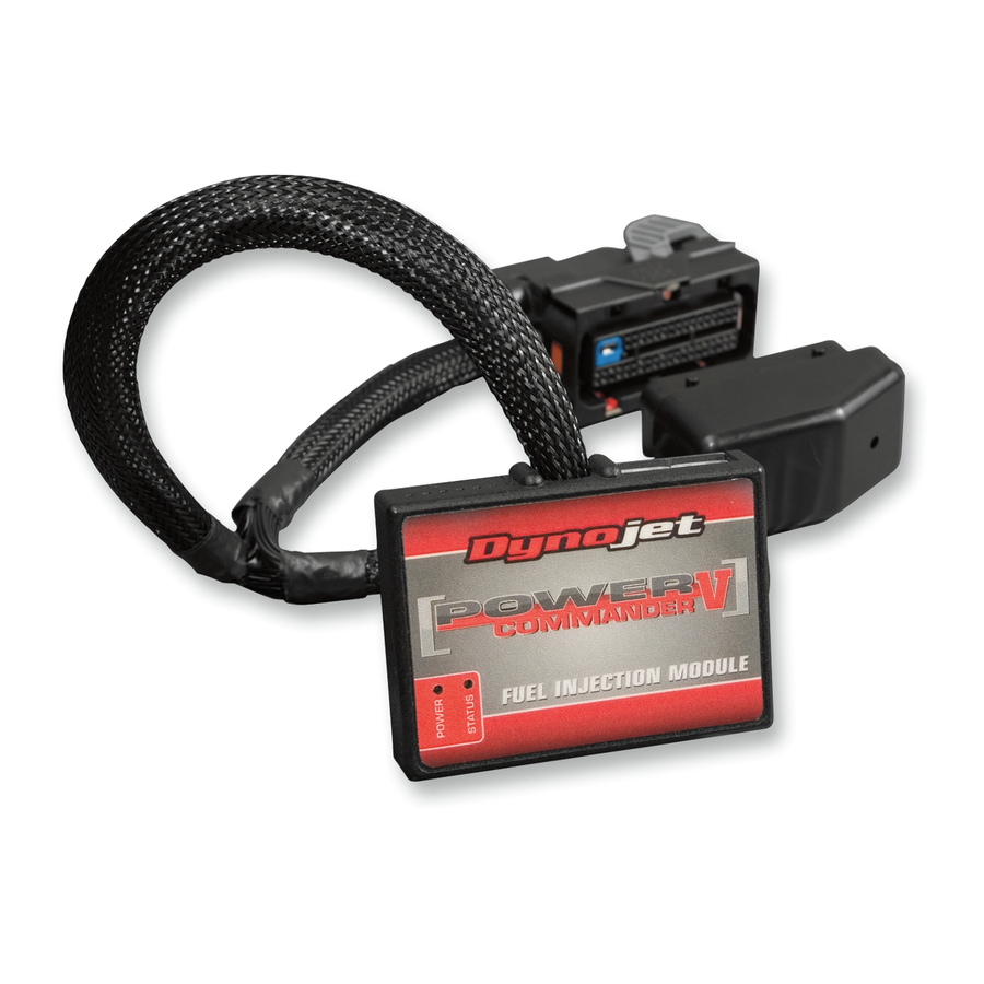
Power Commander
1
USB Cable
1
Installation Guide
2
Power Commander Decals
2
Dynojet Decals
2
Velcro strips
1
Alcohol swab
THE IGNITION MUST BE TURNED
OFF BEFORE INSTALLATION!
THE LATEST POWER COMMANDER
SOFTWARE AND MAP FILES CAN BE
DOWNLOADED FROM OUR WEB SITE AT:
www.powercommander.com
2017-2018 Suzuki DL1000 (V-Strom) - PCV - 1

Related Manuals for Dynojet POWER COMMANDER V


Summary of Contents for Dynojet POWER COMMANDER V
- Page 1 Installation Guide 2017-2018 Suzuki DL1000 (V-Strom) Power Commander Decals I n s t a l l a t i o n I n s t r u c t i o n s Dynojet Decals Velcro strips Alcohol swab THE IGNITION MUST BE TURNED OFF BEFORE INSTALLATION!
-
Page 2: Usb Connection
POWER COMMANDER V INPUT ACCESSORY GUIDE ACCESSORY INPUTS Map - (Input 1 or 2) The PCV has the ability to hold 2 different base maps. You can switch on the fly between these two base maps when you hook up a switch to the MAP inputs. You can USB CONNECTION use any open/close type switch. The polarity of the wires is not important. When using the Autotune kit one position will hold a base map and the other position will let you activate the learning mode. When the switch is “CLOSED” Autotune will be activated. (Set to Switch Input #1 by default.) Shifter- (Input 1 or 2) These inputs are for use with the Dynojet quickshifter. Insert the wires from the CRANK Dynojet quickshifter into the SHIFTER inputs. ANALOG The polarity of the wires is not important. (Set to Switch Input #2 by default.) SPEED EXPANSION PORTS 1 & 2 INPUT 2 (Grnd) - Page 3 FIG.A Remove Remove Remove Remove the seat, the body panels surrounding the fuel tank, and remove the fuel tank (Fig. A). FIG.B Remove the airbox (Fig. B). Remove FIG.C Using the supplied Velcro, secure the PCV module in the tail section (Fig. C). Clean both surfaces with the supplied alcohol swab prior to applying the Velcro adhesive. Route the PCV wiring harness forward towards the engine following along the left side frame rail. 20-052 www.powercommander.com 2017-2018 Suzuki DL1000 (V-Strom) - PCV - 3...
- Page 4 FIG.D Secure the PCV ground wire with the small ring lug to the negative (-) terminal of the bike’s battery (Fig. D). FIG.E On the left side of the rear cylinder throttle body, locate and unplug the bike’s lower primary Throttle Position Sensor (Fig. E). Unplug There is a secondary TPS with the same connector higher up on the same throttle body. Make sure you are going to the lower primary TPS. FIG.F Plug the pair of the 3-pin connectors on the PCV wiring harness in-line of the bike’s TPS and the stock wiring harness (Fig. F). 20-052 www.powercommander.com 2017-2018 Suzuki DL1000 (V-Strom) - PCV - 4...
- Page 5 FIG.G Locate and unplug the stock Fuel Injectors, which are located between the throttle bodies (Fig. G). The front cylinder Fuel Injector has a stock BROWN connector. The rear cylinder Fuel Injector has a stock GREY connector. FIG.H Plug the pair of leads on the PCV wiring harness with ORANGE colored wires in-line of the front cylinder Fuel Injector and the stock BROWN connector. 10 Plug the pair of leads on the PCV wiring harness with YELLOW colored wires in-line of the rear cylinder Fuel Injector and the stock GREY connector (Fig. H). 11 Reinstall the airbox, fuel tank, body work, and seat. 20-052 www.powercommander.com 2017-2018 Suzuki DL1000 (V-Strom) - PCV - 5...