Dynojet Power commander v Installation Instructions Manual
Ignition control
Hide thumbs
Also See for Power commander v:
- Installation manual (9 pages) ,
- Installation instructions manual (9 pages) ,
- Installation instructions and owner's manuals (8 pages)
Quick Links
2012 Yamaha R1
I n s t a l l a t i o n I n s t r u c t i o n s
PLEASE READ ALL DIRECTIONS BEFORE STARTING INSTALLATION
22-054
www.powercommander.com
2191 Mendenhall Drive North Las Vegas, NV 89081 (800) 992-4993 www.powercommander.com
PARTS LIST
1
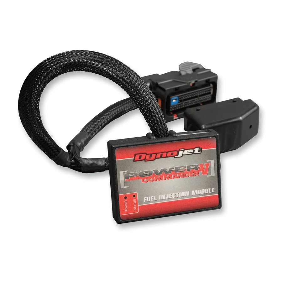
Power Commander
1
USB Cable
1
CD-ROM
1
Installation Guide
2
Power Commander Decals
2
Dynojet Decals
2
Velcro
1
Alcohol swab
1
Posi-tap
1
O2 optimizer
THE IGNITION MUST BE TURNED
OFF BEFORE INSTALLATION!
YOU CAN ALSO DOWNLOAD THE
POWER COMMANDER SOFTWARE AND
LATEST MAPS FROM OUR WEB SITE AT:
www.powercommander.com
2012 Yamaha R1 PCV - 1

Related Manuals for Dynojet Power commander v


Summary of Contents for Dynojet Power commander v
- Page 1 CD-ROM 2012 Yamaha R1 Installation Guide Power Commander Decals I n s t a l l a t i o n I n s t r u c t i o n s Dynojet Decals Velcro Alcohol swab Posi-tap O2 optimizer THE IGNITION MUST BE TURNED...
-
Page 2: Usb Connection
POWER COMMANDER V INPUT ACCESSORY GUIDE ACCESSORY INPUTS Map - The PCV has the ability to hold 2 different base maps. You can switch on the fly between these two base maps when you hook up a switch to the MAP inputs. You can use USB CONNECTION any open/close type switch. The polarity of the wires is not important. When using the Autotune kit one position will hold a base map and the other position will let you activate the learning mode. When the switch is “CLOSED” Autotune will be activated. These inputs are for use with the Dynojet Shifter- quickshifter. Insert the wires from the Dynojet quickshifter into the SHIFTER inputs. The CRANK polarity of the wires is not important. ANALOG Speed- If your application has a speed sensor then SPEED you can tap into the signal side of the sensor EXPANSION PORTS 1 & 2 SHIFTER and run a wire into this input. This will allow... - Page 3 FIG.A Remove the main seat. Lift the front of the fuel tank up and use something to keep it propped up. Remove the inner fairing on the left hand side of the bike (Fig. A). FIG.B Lay the PCV near the battery and route the harness down the left side of the bike. Route the harness underneath the battery bracket (Fig. B). Attach the ground wire of the PCV to the negative side of the battery Ground wire FIG.C Unplug the connectors from the throttle bodies to the main wiring harness (Fig. C). There is a GREEN 3 pin connector and a GREEN 4 pin connector to the inside of the frame on the left side. 22-054 www.powercommander.com 2012 Yamaha R1 PCV - 3...
- Page 4 FIG.D Plug the PCV harness in-line of the stock wiring harness and throttle bodies (Fig. D). FIG.E Unplug the wiring harness from the Throttle Position Sensor (Fig. E). This connector is located on the left side of the throttle bodies underneath the inner fairing that was removed in step 3. FIG.F Using the supplied Posi-tap attach the GREY wire of the PCV to the WHITE wire of the TPS harness (Fig. F). 10 Plug the TPS back on to the throttle bodies 22-054 www.powercommander.com 2012 Yamaha R1 PCV - 4...
- Page 5 11 Install the PCV in the tail section using the supplied velcro if needed (Fig.G). FIG.H 12 Locate the stock O2 sensor connection. This is located under the fuel tank near the right hand side of the frame. It is a BLACK 4 pin connector. 13 Unplug the stock O2 sensor from the main wiring harness (Fig. H). 14 Plug the Dynojet O2 optimizer in-line of the stock wiring harness and O2 sensor (Fig. J). 15 Using the supplied velcro attach the optimizer to the back side of the air box. FIG.J O2 optimizer 16 Reinstall fuel tank back into place and bodywork. Speed input location - Top of engine case on left hand side. PINK wire on sensor side - WHT/YELwire on ECU side.
- Page 6 Tuning Notes: This bike uses a fly-by wire system, so conventional tuning can not be performed for all RPM and throttle ranges. The GREY wire from the PCV is attached to the throttle blade angle sensor of the throttle bodies which is NOT directly correlated to the throttle grip position. Because of this when setting the throttle position in the PCV software we recommend on resetting only the closed position after the bike has completely warmed up. Use the arrow key (<) next to CLOSED to perform this step and then click OK. Do not try to set the OPEN position unless you are on a dyno and above 11000rpm. You will notice that in the maps there are not detailed values below 10500rpm at 60-100%. This is because the throttle blades will not open more than 60% below this RPM range no matter how much throttle input is given. Therefore this area can not be tuned. The O2 optimizer for this model controls the stock closed loop area. This area is represented by the highlighted cells shown in Figure K. The optimizer is designed to achieve a target AFR of 13.6:1. To use this optimizer you must FIG.K retain your stock O2 sensor. It is not necessary to input values in the highlighted area. If using the Auto tune system do NOT input values in this area in your Target AFR table. The Optimizer will blink while the sensor is being heated up. The units are not functioning until the light is lit up solid. 22-054 www.powercommander.com 2012 Yamaha R1 PCV - 6...