Dynojet Power Commander V Installation Manual
2009-2013 honda goldwing / fb6
Hide thumbs
Also See for Power Commander V:
- Installation instructions manual (9 pages) ,
- Installation instructions and owner's manuals (8 pages) ,
- Installation manual (7 pages)
Quick Links
2009-2013 Honda Goldwing / FB6
I n s t a l l a t i o n I n s t r u c t i o n s
PLEASE READ ALL DIRECTIONS BEFORE STARTING INSTALLATION
16-044
www.powercommander.com
2191 Mendenhall Drive North Las Vegas, NV 89081 (800) 992-4993 www.powercommander.com
PARTS LIST
1
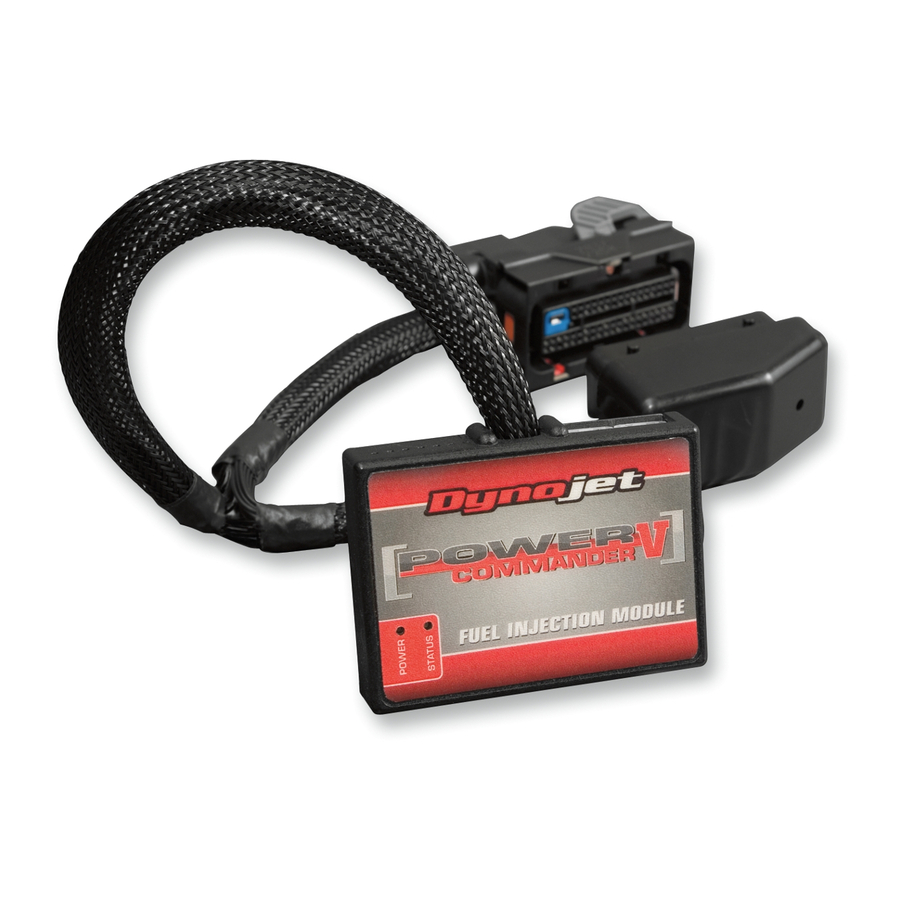
Power Commander
2
USB Cables
1
Installation Guide
2
Power Commander Decals
2
Dynojet Decals
4
Velcro strips
1
Alcohol swab
2
O2 Optimizers
1
Secondary Fuel Module
3
Posi-taps
1
CAN Termination Plug
1
18" CAN Link Cable
THE IGNITION MUST BE TURNED
OFF BEFORE INSTALLATION!
THE LATEST POWER COMMANDER
SOFTWARE AND MAP FILES CAN BE
DOWNLOADED FROM OUR WEB SITE AT:
www.powercommander.com
2009-2013 Honda Goldwing/FB6 - PCV - 1

Related Manuals for Dynojet Power Commander V


Summary of Contents for Dynojet Power Commander V
- Page 1 PARTS LIST Power Commander USB Cables Installation Guide Power Commander Decals 2009-2013 Honda Goldwing / FB6 Dynojet Decals Velcro strips I n s t a l l a t i o n I n s t r u c t i o n s Alcohol swab O2 Optimizers Secondary Fuel Module...
-
Page 2: Usb Connection
POWER COMMANDER V INPUT ACCESSORY GUIDE ACCESSORY INPUTS Map - (Input 1 or 2) The PCV has the ability to hold 2 different base maps. You can switch on the fly between these two base maps when you hook up a switch to the MAP inputs. You can USB CONNECTION use any open/close type switch. The polarity of the wires is not important. When using the Autotune kit one position will hold a base map and the other position will let you activate the learning mode. When the switch is “CLOSED” Autotune will be activated. (Set to Switch Input #1 by default.) Shifter- (Input 1 or 2) These inputs are for use with the Dynojet quickshifter. Insert the wires from the CRANK Dynojet quickshifter into the SHIFTER inputs. ANALOG The polarity of the wires is not important. (Set to Switch Input #2 by default.) SPEED EXPANSION PORTS 1 & 2 INPUT 2 (Grnd) - Page 3 FIG.A Remove the side panels directly below the seat on both sides of the bike. Remove the rear engine covers on both sides. Remove Remove the passenger grip handles on both sides of the seat. Remove Remove the seat (Fig. A). FIG.B Remove Remove the upper dash panel that has the speaker grills (Fig. B). FIG.C Remove Remove Remove both of the long thin plastic panels on the outer edges of the lower Remove Remove dash panel. Remove both of the glove compartments on both sides and the small panels directly below the glove compartments (Fig. B). Remove Remove 16-044 www.powercommander.com 2009-2013 Honda Goldwing/FB6 - PCV - 3...
- Page 4 FIG.D Remove the entire lower dash panel (Fig. D). Remove FIG.E Remove the left side air scoop (Fig. E). Remove FIG.F Remove 10 Remove the upper and lower front cowl panels (Fig. F). 16-044 www.powercommander.com 2009-2013 Honda Goldwing/FB6 - PCV - 4...
- Page 5 FIG. G 11 Route the PCV harness branch with the pair of BLACK 10-pin connectors through the location shown in Figure G. This area is underneath the left air scoop that was removed in Step. 9. You can follow along side the cable for the vents. FIG.H 12 At the front of the bike, locate and unplug the stock connector for the left fuel injector bank (Fig. H). Unplug This is a BLACK 10-pin connector just inside of the frame on the left side. It is difficult to access. FIG.J 13 Plug the matching pair of connectors of the PCV harness in-line with the stock connectors (Fig. J).
- Page 6 FIG.K 14 Secure the ground wire of the PCV harness branch with the 6mm ring lug to this bolt at the front of the engine, shown in Figure K. Ground FIG.L 15 Reinstall the left air scoop. 16 Use 2 of the supplied Velcro strips to secure the PCV module on top of the left air scoop (Fig. L). Clean the surface with the supplied alcohol swab prior to applying the Velcro. 17 Route the PCV harness branch with unterminated wires towards the BLACK connector of the bike’s ECM. 18 Use the 3 supplied Posi-taps to attach the 3 FIG.M unterminated PCV wires to the 3 appropriate wires of the bike’s ECM (Fig. M). The PCV GREY wire goes to the stock LIGHT GREEN wire on the BLACK ECM connector.
- Page 7 19 Use 2 of the supplied Velcro strips to secure the Secondary Fuel Module to FIG.N the top of the right air scoop at the location shown in Figure N. Clean the surface with the supplied alcohol swab prior to applying the Velcro. 20 Plug the supplied CAN Termination Plug into one of the expansion ports at the top of the SFM module. This is a hard plastic CAN port plug supplied in the kit. This is a crucial step that is often overlooked. 21 Plug the supplied CAN link cable into the other expansion port on the SFM module and route the CAN link cable to the primary PCV module on the opposite (left) air scoop.
- Page 8 FIG.Q Unplug 25 Plug the pair of matching connectors on the SFM harness in-line with the stock connectors. 26 Locate and unplug the stock connector for the right O2 sensor in this same connector bundle (Fig. Q). This is also a BLACK 4-pin connector, except this one should have 2 WHITE wires, a BLACK, and a GREY wire. FIG.R 27 Plug the supplied O2 Optimizer (with female pins) into the stock wiring harness in place of the stock O2 sensor (Fig. P). The stock O2 sensor will no longer be used. It can be removed from the exhaust, if desired and if you have a way to plug the hole.
- Page 9 FIG.T Unplug 29 Locate and unplug the stock connector for the left O2 sensor (Fig. T). This is located on the left side of the frame. It is a BLACK 4-pin connector. 30 Plug the supplied O2 Optimizer (with male pins) into the stock wiring harness FIG.U in place of the stock O2 sensor (Fig. U). The stock O2 sensor will no longer be used. It can be removed from the exhaust, if desired and if you have a way to plug the hole. 31 Reassemble the bike.