Dynojet Power Commander V Installation Manual
2014-2015 ducati m1200
Hide thumbs
Also See for Power Commander V:
- Installation instructions manual (9 pages) ,
- Installation manual (9 pages) ,
- Installation instructions and owner's manuals (8 pages)
Quick Links
2014-2015 Ducati M1200
I n s t a l l a t i o n I n s t r u c t i o n s
PLEASE READ ALL DIRECTIONS BEFORE STARTING INSTALLATION
14-026
www.powercommander.com
2191 Mendenhall Drive North Las Vegas, NV 89081 (800) 992-4993 www.powercommander.com
PARTS LIST
1
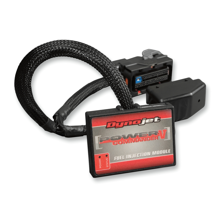
Power Commander
1
USB Cable
1
Installation Guide
2
Power Commander Decals
2
Dynojet Decals
2
Velcro strips
1
Alcohol swab
THE IGNITION MUST BE TURNED
OFF BEFORE INSTALLATION!
THE LATEST POWER COMMANDER
SOFTWARE AND MAP FILES CAN BE
DOWNLOADED FROM OUR WEB SITE AT:
www.powercommander.com
14-15 Ducati M1200 - PCV F/I - 1

Related Manuals for Dynojet Power Commander V


Summary of Contents for Dynojet Power Commander V
- Page 1 Installation Guide 2014-2015 Ducati M1200 Power Commander Decals I n s t a l l a t i o n I n s t r u c t i o n s Dynojet Decals Velcro strips Alcohol swab THE IGNITION MUST BE TURNED OFF BEFORE INSTALLATION!
- Page 2 POWER COMMANDER V INPUT ACCESSORY GUIDE ACCESSORY INPUTS Map - (Input 1 or 2) The PCV has the ability to hold 2 different base maps. You can switch on the fly between these two base maps when you hook up a switch to the MAP inputs. You can USB CONNECTION use any open/close type switch. The polarity of the wires is not important. When using the Autotune kit one position will hold a base map and the other position will let you activate the learning mode. When the switch is “CLOSED” Autotune will be activated. (Set to Switch Input #1 by default.) Shifter- (Input 1 or 2) These inputs are for use with the Dynojet quickshifter. Insert the wires from the CRANK Dynojet quickshifter into the SHIFTER inputs. ANALOG The polarity of the wires is not important. (Set to Switch Input #2 by default.) SPEED EXPANSION PORTS 1 & 2 INPUT 2 (Grnd)
- Page 3 FIG.A Remove the seat and lift the fuel tank up. Lay the PCV in the tail section and route down the left side of the frame and go towards the air box. FIG.B Unplug the 6 pin connector on the left shown in Figure A. Unplug the 3 pin connector on the right shown in Figure A. FIG.C Plug the PCV in-line of the stock wiring (Fig. C). Route the remaining connectors from the PCV down the right side of the engine. 14-026 www.powercommander.com 14-15 Ducati M1200 - PCV F/I - 3...
- Page 4 FIG.D Unplug the stock Crank Position Sensor (Fig. D). This is a BLACK, 3 pin connector on the right side of the engine near the coolart overflow reservoir. FIG.E Plug the PCV in-line of the stock CPS and wiring harness. FIG.F Attach the ground wire of the PCV to the case bolt on the left side of the engine (Fig. F). 10 Reinstall fuel tank and seat. Ground NOTE: If you want to adjust the closed loop area you will either need the optional O2 Optimizer or have your ECU reflashed. 14-026 www.powercommander.com 14-15 Ducati M1200 - PCV F/I - 4...