Dynojet POWER COMMANDER V Installation Instructions Manual
Fuel and ignition 2015-2016 kawasaki brute force 750
Hide thumbs
Also See for POWER COMMANDER V:
- Installation instructions manual (9 pages) ,
- Installation manual (9 pages) ,
- Installation instructions and owner's manuals (8 pages)
Quick Links
FIG.
FUEL AND IGNITION
2015-2016 Kawasaki Brute Force 750
I n s t a l l a t i o n I n s t r u c t i o n s
FIG.
FIG.
PLEASE READ ALL DIRECTIONS BEFORE STARTING INSTALLATION
17-065
2191 Mendenhall Drive North Las Vegas, NV 89081 (800) 992-4993 www.powercommander.com
www.powercommander.com
PARTS LIST
1
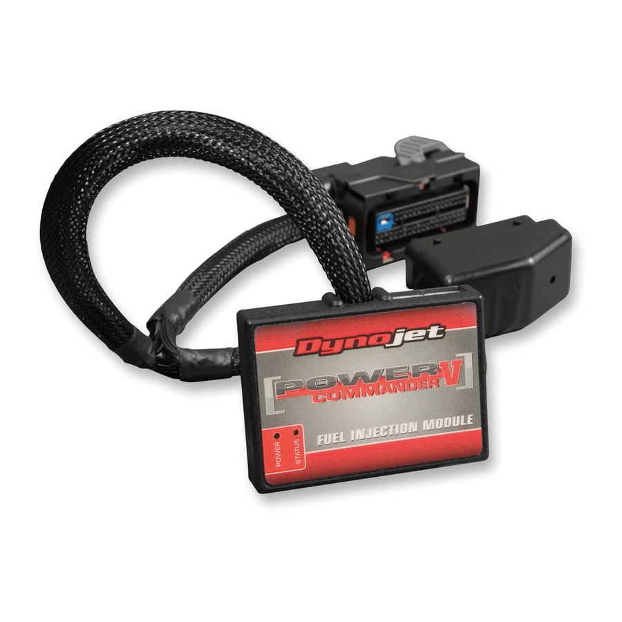
Power Commander
1
USB Cable
1
Installation Guide
2
Power Commander Decals
2
Dynojet Decals
2
Velcro strips
1
Alcohol swab
3
Zip-ties
1
O2 Optimizer
THE IGNITION MUST BE TURNED
OFF BEFORE INSTALLATION!
THE LATEST POWER COMMANDER
SOFTWARE AND MAP FILES CAN BE
DOWNLOADED FROM OUR WEB SITE AT:
www.powercommander.com
15-16 Kawasaki Brute Force 750 - PCV - 1

Related Manuals for Dynojet POWER COMMANDER V


Summary of Contents for Dynojet POWER COMMANDER V
- Page 1 USB Cable Installation Guide FUEL AND IGNITION Power Commander Decals 2015-2016 Kawasaki Brute Force 750 Dynojet Decals Velcro strips I n s t a l l a t i o n I n s t r u c t i o n s FIG. Alcohol swab Zip-ties...
-
Page 2: Usb Connection
POWER COMMANDER V FIG. INPUT ACCESSORY GUIDE ACCESSORY INPUTS Map - (Input 1 or 2) The PCV has the ability to hold 2 different base maps. You can switch on the fly between these two base maps when you hook up a switch to the MAP inputs. You can USB CONNECTION use any open/close type switch. The polarity of the wires is not important. When using the Autotune kit one position will hold a base map and the other position will let you activate the learning mode. When the switch is “CLOSED” Autotune will be activated. (Set to Switch FIG. Input #1 by default.) Shifter- (Input 1 or 2) These inputs are for use with the Dynojet quickshifter. Insert the wires from the CRANK Dynojet quickshifter into the SHIFTER inputs. ANALOG The polarity of the wires is not important. (Set to Switch Input #2 by default.) SPEED EXPANSION PORTS 1 & 2 INPUT 2 (Grnd) - Page 3 FIG.A FIG. Remove Remove the seat. Remove the right hand side cover, and the cover in front of the steering stem that holds the accessory outlet (Fig. A). The shifter knob and key switch will need to be removed to pull the right side cover off. Remove FIG.B FIG. Attach the PCV module to the tray under the seat in the location shown in Figure B. Use the supplied alcohol swab to clean the surface area, prior to making the attachment with the supplied velcro.
- Page 4 FIG.D FIG. Locate the 6-pin BLACK connector on the front head, that comes from the throttle bodies. Unplug this connector (Fig. D). This connector is behind the coolant hose. FIG.E Connect the PCV wiring harness in-line with the stock wiring harness and throttle body harness (Fig. E) . Secure the ground wire of the Power Commander harness to the ground bolt on the shifter bracket (Fig. E). FIG.F Locate the rear ignition coil. It is located on the right hand side of the ATV near the frame rail (Fig. F). 17-065 www.powercommander.com 15-16 Kawasaki Brute Force 750 - PCV - 4...
- Page 5 FIG.G Unplug the BLUE/WHITE wire on the ATV’s rear ignition coil. Connect the set of BLUE colored wires of the PCV harness, in-line of the stock coil and the BLUE/WHITE wire (Fig. G). The BLUE/WHITE wire is the one closer to the engine. FIG.H 10 Continue to route the remainder of the PCV wiring harness down the frame rail and up to where the crank position sensor connectors are located. These connectors are located behind the steering stem cover that was removed in step 1. They are 2-pin connectors, with BLUE and GREEN wires, and are located by the steering stem (Fig.
- Page 6 FIG.J 12 Continue to route the remainder of the PCV wiring harness downward by the steering stem and to the left, where the front ignition coil is located (Fig. J). 13 Unplug the YELLOW/RED wire on the front ignition coil. 14 Connect the set of RED wires of the PCV harness in-line with the coil and theYELLOW/RED wire. FIG.K 15 Unplug the GREEN/WHITE wire on the front ignition coil. 16 Connect the set of GREEN wires of the PCV harness in-line with the coil and the GREEN/WHITE wire (Fig. K). The GREEN/WHITE wire is the one closer to the steering stem. 17 Unplug the stock O2 sensor. FIG.L T his connection is under the seat next to where the PCV is installed. It is a BLACK, 4 pin connector.