Dynojet POWER COMMANDER V Installation Instructions Manual
2017 harley davidson touring model
Hide thumbs
Also See for POWER COMMANDER V:
- Installation manual (9 pages) ,
- Installation instructions manual (9 pages) ,
- Installation instructions and owner's manuals (8 pages)
Quick Links
2017 Harley Davidson Touring Model
I n s t a l l a t i o n I n s t r u c t i o n s
PLEASE READ ALL DIRECTIONS BEFORE STARTING INSTALLATION
15-042
www.powercommander.com
2191 Mendenhall Drive North Las Vegas, NV 89081 (800) 992-4993 www.powercommander.com
PARTS LIST
1
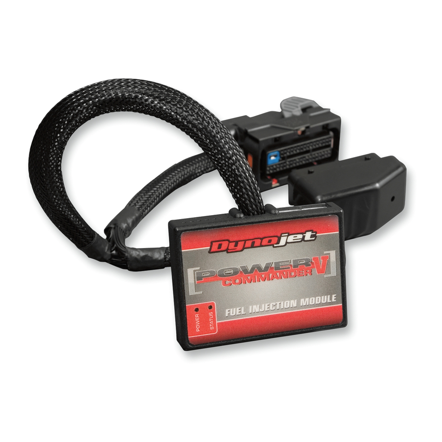
Power Commander
1
USB Cable
1
Installation Guide
2
Power Commander Decals
2
Dynojet Decals
2
Velcro strips
1
Alcohol swab
1
Front O2 Optimizer
1
Rear O2 Optimizer
THE IGNITION MUST BE TURNED
OFF BEFORE INSTALLATION!
THE LATEST POWER COMMANDER
SOFTWARE AND MAP FILES CAN BE
DOWNLOADED FROM OUR WEB SITE AT:
www.powercommander.com
2017 Harley Davidson Touring PCV - 1

Related Manuals for Dynojet POWER COMMANDER V


Summary of Contents for Dynojet POWER COMMANDER V
- Page 1 PARTS LIST Power Commander USB Cable Installation Guide Power Commander Decals 2017 Harley Davidson Touring Model Dynojet Decals I n s t a l l a t i o n I n s t r u c t i o n s Velcro strips Alcohol swab Front O2 Optimizer Rear O2 Optimizer...
- Page 2 POWER COMMANDER V INPUT ACCESSORY GUIDE ACCESSORY INPUTS Map - (Input 1 or 2) The PCV has the ability to hold 2 different base maps. You can switch on the fly between these two base maps when you hook up a switch to the MAP inputs. You can USB CONNECTION use any open/close type switch. The polarity of the wires is not important. When using the Autotune kit one position will hold a base map and the other position will let you activate the learning mode. When the switch is “CLOSED” Autotune will be activated. (Set to Switch Input #1 by default.) Shifter- (Input 1 or 2) Used for clutch-less full throttle upshifts. Insert the wires from the Dynojet quickshifter into either INPUT 1 or INPUT 2. ANALOG The polarity of the wires is not important. (Set to Switch Input #2 by default.) SPEED EXPANSION PORTS 1 & 2 INPUT 2 (Grnd) Speed-...
- Page 3 FIG.A Remove the stock seat and the right side panel Unplug the BLACK and GREY connectors from the ECM (Fig. A) . FIG.B PCV connector PCV connector Route the Female connectors of the PCV behind the frame tube on the right side of the bike as in Figure B. Slide the harness towards the rear of the bike. Ground wire FIG.C Route the stock ECM connectors that were disconnected in step 2 under the frame tube as in Figure C. Stk connector Stk connector 15-042 www.powercommander.com 2017 Harley Davidson Touring PCV - 3...
- Page 4 FIG.D Plug the PCV connectors into the stock ECM (Fig. D). FIG.E Plug the Male connectors of the PCV into the stock Female connectors (Fig. E). FIG.F Secure the PCV under the right hand side cover using the supplied Velcro. Make sure to clean the surface with the alcohol swab before attaching. Figure F is shown on the ABS model. Non ABS models will have more options of where to place the unit. 15-042 www.powercommander.com 2017 Harley Davidson Touring PCV - 4...
- Page 5 There is a GREY 4 pin and a BLACK 4 pin connector under the right hand side cover. FIG.H Plug the Dynojet O2 Optimizers into the stock wiring harness (Fig. H). The stock O2 sensors will NOT be connected to anything at this time. The sensors can be removed from the exhaust if you have a way to plug the hole.
- Page 6 FIG.J Route the 6-pin power plug from the Autotune from the right side of the bike and go in front of the battery to the right side of the bike. Plug the Autotune power lead into the diagnostic port under the left hand side cover (Fig. J). Secure the Autotune lead so it does not get caught in the drive belt. FIG.K Connect the longer harness to the front O2 sensor and then connect to Autotune AT#1. Wire the harness to the module per Figure K. The harness can be cut to length if desired. Repeat step 5 for the rear cylinder. Wire the harness to Autotune module AT#2. The harness can be cut to length if desired. Use the CAN cable to connect the Autotune module to the PCV. It does not FIG.L matter what ports are used. Install the CAN termination plug into the open port of the Autotune module. This is the BLACK plastic connector in the kit (PN: 76423025). It is critical that this piece be installed and it is often overlooked.