Dynojet POWER COMMANDER V Installation Instructions
2008-2010 kawasaki zx10r
Hide thumbs
Also See for POWER COMMANDER V:
- Installation manual (9 pages) ,
- Installation instructions manual (9 pages) ,
- Installation instructions and owner's manuals (8 pages)
Quick Links
2008-2010 Kawasaki ZX10R
Installation Instructions
PLEASE READ ALL DIRECTIONS BEFORE STARTING INSTALLATION
17-004 www.powercommander.com
2191 Mendenhall Drive North Las Vegas, NV 89081 (800) 992-4993 www.powercommander.com
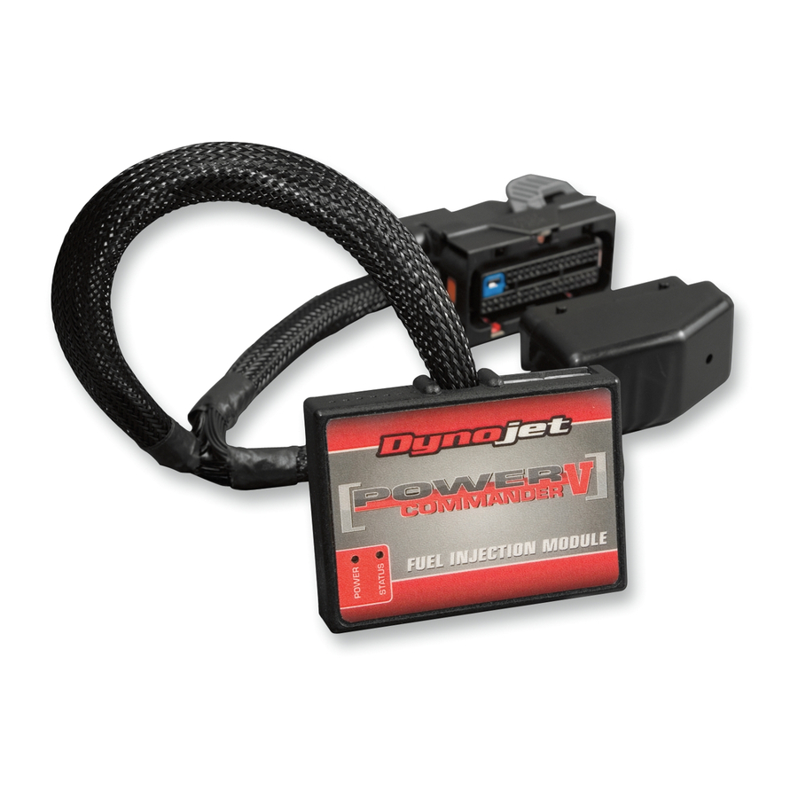
Parts List
1
Power Commander
1
USB Cable
1
CD-ROM
1
Installation Guide
2
Power Commander Decals
2
Dynojet Decals
2
Velcro
Strip
®
1
Alcohol Swab
The ignition MUST be turned
OFF before installation!
YOU CAN ALSO DOWNLOAD THE
POWER COMMANDER SOFTWARE AND
LATEST MAPS FROM OUR WEB SITE AT:
WWW.POWERCOMMANDER.COM
08-10 Kawasaki ZX10R PCV - 1

Related Manuals for Dynojet POWER COMMANDER V


Summary of Contents for Dynojet POWER COMMANDER V
- Page 1 Parts List Power Commander USB Cable CD-ROM 2008-2010 Kawasaki ZX10R Installation Guide Power Commander Decals Installation Instructions Dynojet Decals Velcro Strip ® Alcohol Swab The ignition MUST be turned OFF before installation! YOU CAN ALSO DOWNLOAD THE POWER COMMANDER SOFTWARE AND LATEST MAPS FROM OUR WEB SITE AT: WWW.POWERCOMMANDER.COM PLEASE READ ALL DIRECTIONS BEFORE STARTING INSTALLATION 2191 Mendenhall Drive North Las Vegas, NV 89081 (800) 992-4993 www.powercommander.com...
- Page 2 Do NOT connect anything to this port unless the PCV until is stops and then tighten the instructed to do so by Dynojet. It is used to screw. Make sure to reinstall the rubber plug. transfer crank trigger data from one module to NOTE: If you tin the wires with solder it will another.
- Page 3 FIG. A Remove the main seat and the passenger seat Remove the covers for each side of the fuel tank (Fig. A). Prop the front of the fuel tank up. FIG. B Slide the junction box that is under the main seat from it’s rubber sleeve. This allows room for the PCV harness Route the PCV harness underneath the subframe crossover (Fig. B). FIG. C Unplug the main wiring harness from the throttle bodies (Fig. C). Unplug This is a 16 pin BROWN connector located under the fuel tank on the right hand side of the bike 17-004 www.powercommander.com 08-10 Kawasaki ZX10R PCV - 3...
- Page 4 FIG. D Plug the PCV connectors in-line of the stock wiring harness and throttle body harness (Fig. D). FIG. E PCV harness Attach the ground wire of the PCV to the stock wiring harness chassis ground (Fig. E). This connection is next to the PCV connection and starter relay. FIG. F Install the PCV in the tail section as shown in Figure F. Speed input - BLUE/YELLOW wire. Sensor is located on the left hand side of the engine case in front of the c/s sprocket. Temperature input- Light ORANGE wire on 10 pin GREY connector under fuel tank. 12v source for Autotune - RED wire of tail light connector. 17-004 www.powercommander.com 08-10 Kawasaki ZX10R PCV - 4...