Allen-Bradley Kinetix 5700 User Manual
Hide thumbs
Also See for Kinetix 5700:
- User manual (460 pages) ,
- Reference manual (126 pages) ,
- Installation instructions manual (16 pages)
Table of Contents
Quick Links
User Manual
Original Instructions
Kinetix 5700 Servo Drives
Catalog Numbers 2198-P031, 2198-P070, 2198-P141, 2198-P208, 2198-S086-ERS3, 2198-S130-ERS3, 2198-S160-ERS3,
2198-D006-ERS3, 2198-D012-ERS3, 2198-D020-ERS3, 2198-D032-ERS3, 2198-D057-ERS3, 2198-S086-ERS4,
2198-S130-ERS4, 2198-S160-ERS4, 2198-D006-ERS4, 2198-D012-ERS4, 2198-D020-ERS4, 2198-D032-ERS4,
2198-D057-ERS4, 2198T-W25K-ER, 2198-CAPMOD-2240, 2198-CAPMOD-DCBUS-IO
Table of Contents
Troubleshooting

Related Manuals for Allen-Bradley Kinetix 5700


Summary of Contents for Allen-Bradley Kinetix 5700
- Page 1 User Manual Original Instructions Kinetix 5700 Servo Drives Catalog Numbers 2198-P031, 2198-P070, 2198-P141, 2198-P208, 2198-S086-ERS3, 2198-S130-ERS3, 2198-S160-ERS3, 2198-D006-ERS3, 2198-D012-ERS3, 2198-D020-ERS3, 2198-D032-ERS3, 2198-D057-ERS3, 2198-S086-ERS4, 2198-S130-ERS4, 2198-S160-ERS4, 2198-D006-ERS4, 2198-D012-ERS4, 2198-D020-ERS4, 2198-D032-ERS4, 2198-D057-ERS4, 2198T-W25K-ER, 2198-CAPMOD-2240, 2198-CAPMOD-DCBUS-IO...
- Page 2 Important User Information Read this document and the documents listed in the additional resources section about installation, configuration, and operation of this equipment before you install, configure, operate, or maintain this product. Users are required to familiarize themselves with installation and wiring instructions in addition to requirements of all applicable codes, laws, and standards.
-
Page 3: Table Of Contents
Start About the Kinetix 5700 Servo Drive System ..... 16 Drive Hardware and Input Power Configurations ....18 DC-bus Power Supply Configuration . - Page 4 Connector Data and Feature Kinetix 5700 Connector Data ........64 Safe Torque-off Connector Pinout.
- Page 5 Studio 5000 Logix Designer ........146 Kinetix 5700 Add-On Profile......146 Install the Kinetix 5700 Add-On Profile.
- Page 6 SAFE FLT Fault Codes ........222 Kinetix 5700 Status Indicators......223 Kinetix 5700 Capacitor Module Status Indicators .
- Page 7 Before You Begin..........235 Remove and Replace Kinetix 5700 Drive Modules ....236 Modules Remove Power and All Connections .
- Page 8 Table of Contents Appendix B Upgrade the Drive Firmware Before You Begin..........308 Configure Logix5000 Controller Communication .
- Page 9 Table of Contents SLAT Max Speed/Torque....... . . 349 SLAT Attributes ......... 349 Configure the Axis for SLAT .
- Page 10 Table of Contents Notes: Rockwell Automation Publication 2198-UM002E-EN-P - February 2018...
-
Page 11: Summary Of Changes
Summary of Changes This manual contains new and updated information as indicated in the following table. Table 1 - New and Updated Information Topic Page Added IMPORTANT statement defining the use of catalog numbers 2198-Dxxx-ERSx, 2198-Sxxx-ERSx, or 2198-xxxx-ERSx throughout this manual. Added 2198-xxxx-ERS4 catalog numbers to table and updated compatible controller families. - Page 12 Summary of Changes Table 1 - New and Updated Information (continued) Topic Page Updated bullets for use of MDS instructions. Added Motion Drive Start (MDS) Instruction. Changed Torque Proving section title to Phase Loss Detection. Changed Extended Speed section title to Field Weakening Mode. Rockwell Automation Publication 2198-UM002E-EN-P - February 2018...
-
Page 13: Preface
EtherNet/IP™ communication module or controller. If you do not have a basic understanding of Kinetix 5700 drive modules, contact your local Rockwell Automation sales representative for information on available training courses. - Page 14 Preface Table 2 - Additional Resources (continued) Resource Description Information on installing and wiring the Kinetix 5500 and Kinetix 5700 AC line Kinetix 5000 AC Line Filter Installation Instructions, publication 2198-IN003 filters. Kinetix 5700 Capacitor Modules Installation Instructions, publication 2198-IN008 Information on installing and wiring the Kinetix 5700 capacitor modules.
-
Page 15: Start
Use this chapter to become familiar with the design and installation requirements for Kinetix® 5700 drive systems. Topic Page About the Kinetix 5700 Servo Drive System Drive Hardware and Input Power Configurations Motor and Auxiliary Feedback Configurations Typical Communication Configurations... -
Page 16: About The Kinetix 5700 Servo Drive System
Bulletin 1321 line reactors help keep equipment running longer by absorbing many of the power line disturbances that Line Reactors 1321-3RA80-B can shut down your power supply. 2198-TCON-24VDCIN36 24V input wiring connectors, T-connectors, and bus-bars for the Kinetix 5700 drive system 24V shared-bus connection 2198-xxxx-P-T system (optional). 2198-BARCON-xxDCAC100 Shared-bus... - Page 17 2198-DB20-F, 2198-DB42-F, AC Line Filters 2198-DB80-F, 2198-DB290-F Bulletin 2198 three-phase AC line filters are required to meet CE and available for use in all Kinetix 5700 drive systems. 24V DC Power Supply 1606-XLxxx Bulletin 1606 24V DC power supply for control circuitry, digital inputs, safety, and motor brake.
-
Page 18: Drive Hardware And Input Power Configurations
Chapter 1 Start Drive Hardware and Input Kinetix 5700 servo drive systems have three-phase input power supplied by a single DC-bus (converter) power supply. However, for additional output Power Configurations power (kW) you can install two or three 2198-P208 power supplies or an 8720MC-RPS regenerative power supply. -
Page 19: Multiple Dc-Bus Power Supply Configuration
Contactor-enable relays from each of the DC-bus power supplies are wired in series to protect the DC-bus power supply in the event of shutdown fault conditions. Figure 2 - Multiple DC-bus Power Supply Installation Bulletin 2198 Kinetix 5700 Servo Drive System Shunt Module (top view) (optional component) Shared DC-bus Power Input... -
Page 20: 8720Mc-Rps Power Supply Configuration
In this example, three-phase AC input power is fed to the Bulletin 8720MC regenerative power supply. The 8720MC-RPS DC-bus voltage supplies the Kinetix 5700 DC-bus via the capacitor module. If the 8720MC-RPS190 is used, the 2198-CAPMOD-DCBUS-IO extension module is required. -
Page 21: Extended Dc-Bus Configuration
In this example, two drive clusters in the same cabinet are connected by the same 450…750V DC bus voltage. Kinetix 5700 capacitor modules provide connection points for the DC bus at the end of cluster 1 and the beginning of cluster 2. -
Page 22: Itrak Power Supply Configuration
The contactor-enable relay protects the DC-bus power supply in the event of shutdown fault conditions. Figure 5 - Typical iTRAK Power Supply Installation Bulletin 2198 Kinetix 5700 iTRAK System Shunt Module (top view) (optional component) Shared DC-bus Power Input... -
Page 23: Motor And Auxiliary Feedback Configurations
Start Chapter 1 Motor and Auxiliary Feedback connections are made at the 2-pin motor feedback (MF) connector and the 15-pin universal feedback (UFB) connector. These examples illustrate Feedback Configurations how you can use the Bulletin 2198 connector kits for making these connections. -
Page 24: Typical Communication Configurations
Chapter 1 Start Typical Communication The Kinetix 5700 drives support any Ethernet topology including linear, ring, and star by using ControlLogix, GuardLogix, or CompactLogix controllers. Configurations These examples feature the ControlLogix 5570 programmable automation controllers with support for integrated motion and integrated safety over the EtherNet/IP network. -
Page 25: Ring Topology
Embedded Switch Technology Application Guide, publication ENET-AP005. Devices without dual ports, for example the display terminal, require a 1783-ETAP module to complete the network ring. Figure 8 - Kinetix 5700 Ring Communication Installation ControlLogix Controller Programming Network EtherNet/IP ControlLogix 5570 Controller... -
Page 26: Star Topology
Kinetix 5700 drive modules have dual ports, so linear topology is maintained from one module to another, but the Kinetix 5700 system and other devices operate independently. The loss of one device does not impact the operation of other devices. -
Page 27: Functional Safety Configurations
Start Chapter 1 Functional Safety Kinetix 5700 servo drives are capable of safe torque-off (STO) and safe stop 1 (SS1) drive-based safety functions via hardwired connections or integrated Configurations over the EtherNet/IP network. In addition, safely limited speed (SLS) and other controller-based safety instructions are also possible. -
Page 28: Integrated Safety Configurations
The GuardLogix or Compact GuardLogix safety controller issues the safe torque-off (STO) or safe stop (SS1) command over the EtherNet/IP network and the Kinetix 5700 servo drive executes the command. In this example, a single GuardLogix safety controller makes the Motion and Safety connections. - Page 29 EtherNet/IP Studio 5000 Logix Designer LNK1 LNK2 NET OK 1783-BMS Application Stratix 5700 (version 31.00 or later) Switch Kinetix 5700 Servo Drive System 1585J-M8CBJM-x Any Logix5000 Controller (top view) Ethernet (shielded) Cable (ControlLogix 5570 controller is shown) Motion Program 1734-AENTR...
-
Page 30: Safe Stop And Safe Monitor Configurations
Chapter 1 Start Safe Stop and Safe Monitor Configurations Kinetix 5700 servo drives are capable of safe stop and safe monitor functions via drive-based and controller-based integrated safety over the EtherNet/IP network. IMPORTANT For applications with drive-based or controller-based safety functions, the 2198-xxxx-ERS4 inverters and GuardLogix 5580 or Compact GuardLogix 5380 controllers must be used. -
Page 31: Catalog Number Explanation
Start Chapter 1 Catalog Number Explanation Kinetix 5700 drive module catalog numbers and performance descriptions. Table 4 - Kinetix 5700 Drive Module Catalog Numbers Module Continuous Output Continuous Output Continuous Output Kinetix 5700 Drive Width Power Current to Bus Current Cat. -
Page 32: Agency Compliance
• Motor cable length for iTRAK power supply to iTRAK motor modules must at least 3 m (9.8 ft), not to exceed 30 m (98.4 ft). • Install the Kinetix 5700 system inside an approved enclosure. Run input power wiring in conduit (grounded to the enclosure) outside of the enclosure. -
Page 33: Plan The Kinetix 5700 Drive System Installation
Chapter Plan the Kinetix 5700 Drive System Installation This chapter describes system installation guidelines used in preparation for mounting your Kinetix® 5700 drive system components. Topic Page System Design Guidelines Electrical Noise Reduction ATTENTION: Plan the installation of your system so that you can perform all cutting, drilling, tapping, and welding with the system removed from the enclosure. -
Page 34: System Design Guidelines
AutoCAD (DXF) drawings of the product, refer to https://www.rockwellautomation.com/global/support/selection.page. System Mounting Requirements • To comply with UL and CE requirements, the Kinetix 5700 drive systems must be enclosed in a grounded conductive enclosure offering protection as defined in standard EN 60529 (IEC 529) to IP54 such that they are not accessible to an operator or unskilled person. -
Page 35: Transformer Selection
However, a transformer can be required to match the voltage requirements of the power supply to the available service. To size a transformer for the main AC power inputs, refer to the Kinetix 5700 power specifications in the Kinetix Servo Drives Technical Data, publication KNX-TD003. -
Page 36: Contactor Specifications
Chapter 2 Plan the Kinetix 5700 Drive System Installation Input Power UL/CSA Circuit-protection Specifications Kinetix 5700 Drives UL/CSA Applications Motor Protection CB, DC-bus Power Supply Drive Voltage Bussmann Fuses Miniature CB Molded Case CB Self Protected CMC Cat. No. (three-phase) nom Cat. -
Page 37: Enclosure Selection
If the maximum ambient rating of the Kinetix 5700 drive system is 50 °C (122 °F) and if the maximum environmental temperature is 20 °C (68 °F), then T=30. In this example, the total heat dissipation is 416 W (sum of all components in enclosure). -
Page 38: Minimum Clearance Requirements
Chapter 2 Plan the Kinetix 5700 Drive System Installation Table 8 - Power Dissipation Specifications Usage as % of Rated Power Output (watts) DC-bus Power Supply Cat. No. 100% 2198-P031 2198-P070 2198-P141 2198-P208 Dual-axis Inverter Cat. No. 2198-D006-ERSx 2198-D012-ERSx 2198-D020-ERSx... - Page 39 Plan the Kinetix 5700 Drive System Installation Chapter 2 Figure 14 - Minimum Clearance Requirements 40 mm (1.57 in.) clearance above 29.5 (1.16) module for airflow and installation. Clearance above for wiring to DC-bus Clearance where cover and studs and lug cover installation.
-
Page 40: Electrical Noise Reduction
Electrical Noise Reduction This section outlines best practices that minimize the possibility of noise- related failures as they apply specifically to Kinetix 5700 system installations. For more information on the concept of high-frequency (HF) bonding, the ground plane principle, and electrical noise reduction, refer to the System Design for Control of Electrical Noise Reference Manual, publication GMC-RM001. - Page 41 Plan the Kinetix 5700 Drive System Installation Chapter 2 These illustrations show details of recommended bonding practices for painted panels, enclosures, and mounting brackets. Figure 16 - Recommended Bonding Practices for Painted Panels Stud-mounting the Subpanel Stud-mounting a Ground Bus...
-
Page 42: Bonding Multiple Subpanels
Chapter 2 Plan the Kinetix 5700 Drive System Installation Bonding Multiple Subpanels Bonding multiple subpanels creates a common low impedance exit path for the high frequency energy inside the cabinet. Subpanels that are not bonded together do not necessarily share a common low impedance path. This... -
Page 43: Establishing Noise Zones
Plan the Kinetix 5700 Drive System Installation Chapter 2 Establishing Noise Zones Observe these guidelines when routing cables used in the Kinetix 5700 system: • The clean zone (C) is right of the drive system and includes the digital inputs wiring and Ethernet cable (gray wireway). -
Page 44: Cable Categories For Kinetix 5700 Systems
Chapter 2 Plan the Kinetix 5700 Drive System Installation Cable Categories for Kinetix 5700 Systems These tables indicate the zoning requirements of cables connecting to the Kinetix 5700 drive system components. Table 9 - DC-bus Power Supplies Zone Method Wire/Cable... -
Page 45: Noise Reduction Guidelines For Drive System Accessories
43 for an example): • Mount the AC line filter on the same panel as the Kinetix 5700 power supply and as close to the power supply as possible. • Good HF bonding to the panel is critical. For painted panels, refer to... - Page 46 Chapter 2 Plan the Kinetix 5700 Drive System Installation External Passive Shunt Modules Observe these guidelines when mounting your 2198-R014, 2198-R031, or 2198-R127 external passive shunt modules: • Mount the shunt module outside of the drive system enclosure. • Mount the shunt module so that wiring routes in the very dirty zone inside the drive system enclosure.
- Page 47 Plan the Kinetix 5700 Drive System Installation Chapter 2 Observe these guidelines when mounting your 2198-R004 external passive shunt resistor: • Mount the shunt resistors anywhere in the dirty zone, but as close to the Kinetix 5700 power supply as possible.
- Page 48 Chapter 2 Plan the Kinetix 5700 Drive System Installation Notes: Rockwell Automation Publication 2198-UM002E-EN-P - February 2018...
- Page 49 SHOCK HAZARD: To avoid the hazard of electrical shock, perform all mounting and wiring of the Kinetix 5700 drive system before applying power. Once power is applied, connector terminals can have voltage present even when not in use.
-
Page 50: Determine Mounting Order
IMPORTANT The DC-bus power supplies (1…3 modules) must be positioned on the far left. Position your single-axis inverter modules to the right of the DC-bus power supplies and the dual-axis inverter modules on the far right. Table 14 - Kinetix 5700 Single-axis Inverter Modules Attribute 2198-S086-ERSx... - Page 51 IMPORTANT The maximum number of inverter modules depends on the maximum system capacitance of the power supply and the total system capacitance of all Kinetix 5700 system capacitance values. When there are two or three DC-bus power supplies, they must be catalog number 2198-P208.
-
Page 52: Mounting Capacitor Modules
Chapter 3 Mount the Kinetix 5700 Drive System Mounting Capacitor Modules Mount the 2198-CAPMOD-2240 capacitor module on the far right or far left of any system cluster, depending on the input power configuration. More than one capacitor module can be used in a cluster, if needed. Each additional module adds to the total system capacitance and increased energy storage. - Page 53 Mount the Kinetix 5700 Drive System Chapter 3 Figure 25 - DC-bus Power Supply Example/Multiple Capacitor Modules (200 A, max) DC-Bus Single-axis Capacitor Capacitor Dual-axis Power Supply Inverters Inverters Module Module This example includes: • 1 Bus group DC Bus •...
-
Page 54: Zero-Stack Tab And Cutout
Figure 28 - Zero-stack Tab and Cutout Example Zero-stack Tab and Cutout Engaged Kinetix 5700 Drive Modules (front view) For Kinetix 5700 system sizing examples, refer to Appendix C on page 317. Shared-bus Connection The shared-bus connection system is used to extend the DC-bus power and 24V control power from one drive module to another. -
Page 55: 24V Input Power Connection System
Mount the Kinetix 5700 Drive System Chapter 3 Figure 29 - DC-bus Connector Example End Caps (2) DC-bus Link, 85 mm Align the DC-bus link DC-bus Link, 55 mm lower pivots with the DC-bus Link, 100 mm latches and push downward (seated) until they latch. -
Page 56: Drill-Hole Patterns
3. Insert bus-bars to connect between wiring connector and T-connectors. Drill-hole Patterns This section provides drill-hole patterns for Kinetix 5700 drive modules that are mounted in zero-stack (shared-bus) configurations. Properly spaced drill- holes are essential for engaging the zero-stack tab and cutout from module-to- module so that the DC-bus connectors are spaced properly to accept the DC- bus links. -
Page 57: Drill-Hole Pattern Calculations
3. The next hole location is 55 mm. 4. Repeat step 2 step 3 for the remaining holes. Figure 31 - Kinetix 5700 Mounting Hole Patterns Dimensions are in mm (in.) 27.5 (1.08) 45.0 (1.77) See Mounting Hole Pattern Calculations First Mounting Hole 45.0 (1.77) See Mounting Hole Pattern Calculations... -
Page 58: Drill-Hole Patterns By Using The System Mounting Toolkit
Chapter 3 Mount the Kinetix 5700 Drive System Drill-hole Patterns by Using the System Mounting Toolkit The mounting bar must be mounted horizontally on the system panel. The drill-hole guide inserts behind the mounting bar and slides left and right. Holes and slots in the drill-hole guide let you establish the location of each Kinetix 5700 drive module. - Page 59 Mount the Kinetix 5700 Drive System Chapter 3 In this example, the leftmost module is 85 mm wide. Center of Leftmost Module Horizontal Line Drawn on Panel Right-side Alignment Slot EXT MODULE 7. Draw a line along the left edge of the right-side alignment slot appropriate for the drive-width of module being mounted.
- Page 60 Chapter 3 Mount the Kinetix 5700 Drive System Figure 33 - Kinetix 5700 System Mounting Toolkit Upper Module-width Holes Left-side Alignment Slots Right-side Alignment Slots Right-side Alignment Slot Reference Lines EXT MODULE Always draw your lines in the Extension Module Lower Hole slot on the side marked with the reference lines.
-
Page 61: Mount Your Kinetix 5700 Drive Modules
Follow these steps to mount your Kinetix 5700 drive modules to the panel. 1. Lay out the hole pattern for each drive module in the enclosure. Establishing Noise Zones... - Page 62 Chapter 3 Mount the Kinetix 5700 Drive System Notes: Rockwell Automation Publication 2198-UM002E-EN-P - February 2018...
- Page 63 This chapter illustrates connectors and indicators for the Kinetix® 5700 drive system components, including the DC-bus power supply, single-axis inverter, and dual-axis inverter modules. Also included in this chapter are connector pinouts and descriptions for Kinetix 5700 system components. Topic Page...
-
Page 64: Kinetix 5700 Connector Data
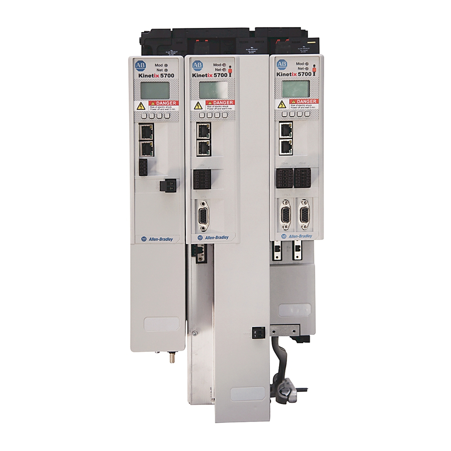
Chapter 4 Connector Data and Feature Descriptions Kinetix 5700 Connector Data Use these illustrations to identify the connectors and indicators for the Kinetix 5700 drive modules. Figure 34 - DC-bus Power Supply Features and Indicators MOD– NET– 5700 DC– 24V–... - Page 65 Connector Data and Feature Descriptions Chapter 4 Figure 35 - Dual-axis Inverter Features and Indicators MOD– NET– 5700 I/O-B I/O-A DC– 24V– UFB-A UFB-B 24V+ SB+/NC MF-A MF-B Dual-axis Inverter, Bottom View Dual-axis Inverter, Top View (2198-D006-ERSx module is shown) (2198-D006-ERS3 module is shown) Dual-axis Inverter, Front View (2198-D006-ERS3 module is shown)
- Page 66 Chapter 4 Connector Data and Feature Descriptions Figure 36 - Single-axis Inverter Features and Indicators MOD– NET– 5700 DC– 24V– 24V+ SB+/NC Single-axis Inverter, Top View Single-axis Inverter, Bottom View (2198-S086-ERS3 module is shown) (2198-S086-ERSx module is shown) Single-axis Inverter, Front View (2198-S086-ERS3 module is shown) –...
- Page 67 Connector Data and Feature Descriptions Chapter 4 Figure 37 - iTRAK® Power Supply Features and Indicators MOD– NET– 5700 – iPS RDY IN 24V - IN 24V + iTRAK Power Supply (bottom view) iTRAK Power Supply (top view) iTRAK Power Supply (front view) iTRAK Power Supply (left side view)
-
Page 68: Safe Torque-Off Connector Pinout
Chapter 4 Connector Data and Feature Descriptions Safe Torque-off Connector Pinout The hardwired safe torque-off (STO) connector pinouts apply to single-axis and dual-axis inverters. For feature descriptions and wiring information, refer Chapter 9 beginning on page 254. Input Power Connector Pinouts The AC input power (IPD) and contactor-enable (CED) connector pinouts apply to DC-bus power supply. -
Page 69: Dc Bus And Shunt Resistor Connector Pinouts
Connector Data and Feature Descriptions Chapter 4 DC Bus and Shunt Resistor Connector Pinouts The DC-bus (DC) connector pinout applies to DC-bus power supply, single- axis inverter, dual-axis inverter, and iTRAK power supply. The shunt resistor (RC) pinout applies to the DC-bus power supply. Table 21 - DC Bus Power Connector DC Pin Description... - Page 70 Chapter 4 Connector Data and Feature Descriptions Single-axis and dual-axis inverters have four configurable digital inputs with fast response times and ten configurable functions to choose from in the Logix Designer application. Table 25 - Inverter Digital Input Pinouts IOD Pin Description Signal 24V current sinking fast input #1...
-
Page 71: Ethernet Communication Connector Pinout
Three-phase motor power Black Blue Chassis ground Green ATTENTION: To avoid damage to the Kinetix 5700 DC-bus power supply and inverter, make sure the motor power signals are wired correctly. Refer to Figure 71 Figure 72 beginning on page 112 for connector wiring examples. -
Page 72: Motor Feedback Connector Pinouts
Chapter 4 Connector Data and Feature Descriptions Motor Feedback Connector Pinouts These connector pinouts apply to the single-axis and dual-axis inverter. Table 30 - DSL Feedback Connector MF Pin Description Signal Bidirectional data and power for digital encoder interface D– Cable shield and grounding plate (internal to 2198-KITCON-DSL connector kit) termination point. -
Page 73: Universal Feedback Connector Pinouts
Connector Data and Feature Descriptions Chapter 4 Universal Feedback Connector Pinouts These connector pinouts apply to the single-axis and dual-axis inverter. Table 31 - Stegmann Hiperface and TTL Sine/Cosine Universal Feedback Connector UFB Pin Description Signal UFB Pin Description Signal Sine differential input + MTR_SIN+ Clock output +... -
Page 74: Understand Control Signal Specifications
Regeneration OK Non-CIP Motion™ Converter and assigned to Regenerative OK. This signal is wired from RDY on the 8720MC-RPS unit and indicates to the Kinetix 5700 drive system that the 8720MC-RPS unit is ready to supply power. Enabled inverters enumerate a Bus Power Sharing fault if the Regeneration OK input goes inactive. -
Page 75: Ethernet Communication Specifications
125 μs, min Figure 42 - Digital Input Circuitry IOD-1 or IOD-3 INPUT 24V DC IOD-2 Kinetix 5700 Drive Ethernet Communication Specifications The PORT1 and PORT2 (RJ45) Ethernet connectors are provided for communication with the Logix5000™ controller. Attribute Value The drive auto-negotiates speed and duplex modes. These modes can Communication be forced through the Logix Designer application. -
Page 76: Contactor Enable Relay
• three-phase power is removed and the DC-bus power supply is protected under various fault conditions. • three-phase power is never applied to the Kinetix 5700 drive system before control power is applied. Figure 43 - Contactor-enable Relay Circuit... - Page 77 Turn-on and turn-off delays are specified by the MechanicalBrakeEngageDelay and MechanicalBrakeReleaseDelay settings. IMPORTANT Holding brakes that are available on Allen-Bradley® rotary motors are designed to hold a motor shaft at 0 rpm for up to the rated brake- holding torque, not to stop the rotation of the motor shaft, or be used as a safety device.
-
Page 78: Control Power
Chapter 4 Connector Data and Feature Descriptions Control Power The Kinetix 5700 drive modules require 24V DC (21.6…26.4V) input power for control circuitry. IMPORTANT SELV or PELV rated power supplies must be used to energize external safety devices connected to the Kinetix 5700 safety inputs. -
Page 79: Feedback Specifications
(UFB) feedback connector for those motors and actuators. Encoder Feedback Supported on the UFB Feedback Connector The Kinetix 5700 drives also support multiple types of feedback devices by using the 15-pin (UFB) universal feedback connector and sharing connector pins in many cases. Use the 2198-K57CK-D15M universal feedback connector kit for terminating the feedback conductors. - Page 80 Figure 45 - Motor Thermostat Interface 8.25 kΩ 1 kΩ Jumper MTR_TS 0.1 μF Kinetix 5700 Servo Drive Rockwell Automation Publication 2198-UM002E-EN-P - February 2018...
- Page 81 Connector Data and Feature Descriptions Chapter 4 Stegmann Hiperface Feedback Figure 46 - Stegmann Hiperface Interface, MTR_SIN and MTR_COS Signals 220 pF Kinetix 5700 Servo Drive 2 kΩ 1 kΩ to A/D Converter 1 kΩ 220 pF 2 kΩ 1 kΩ...
- Page 82 Hall inputs Single-ended, TTL, open collector, or none (MTR_S1, MTR_S2, and MTR_S3) Figure 48 - Generic TTL Incremental, MTR_AM and MTR_BM Signals 220 pF Kinetix 5700 Servo Drive 2 kΩ 1 kΩ to A/D Converter 1 kΩ...
- Page 83 Connector Data and Feature Descriptions Chapter 4 Figure 49 - Generic TTL Interface, MTR_IM Signals Kinetix 5700 Servo Drive 1 kΩ MTR_IM+ 121 Ω to AqB Counter 1 kΩ MTR_IM- 56 pF 56 pF Shaded area indicates components that are part of the circuit, but support other feedback device types (not used for Generic TTL incremental support).
- Page 84 Chapter 4 Connector Data and Feature Descriptions Generic Sine/Cosine Feedback Table 39 - Generic Sine/Cosine Incremental Specifications Attribute Value Sine/Cosine interpolation 2048 counts/sine wave period Input frequency 250 kHz, max (MTR_SIN and MTR_COS) Differential input voltage 0.6…1.2V, p-p (MTR_SIN and MTR_COS) Commutation angle verification performed at the first Hall signal Commutation verification transition and periodically verifies thereafter...
- Page 85 EnDat sine/cosine interface schematic. It is identical to the Stegmann Hiperface (MTR_SIN and MTR_COS) schematic. Figure 51 - EnDat Sin/Cos and EnDat Digital Interface Schematic for Serial Communication Kinetix 5700 Servo Drive Shaded area indicates components that are part of the circuit, but support other feedback device types (not used for EnDat support).
-
Page 86: Auxiliary Feedback Specifications
Contact your local distributor or Rockwell Automation representative for support options. Auxiliary Feedback Specifications The Kinetix 5700 inverters support multiple types of feedback devices by using the 15-pin (UFB) connector and sharing connector pins in many cases. Refer Configure Feedback-only Axis Properties... - Page 87 Allen-Bradley Bulletin 842HR, 844D, 847H, and 847T encoders are the preferred encoders for auxiliary feedback connections. Table 44 - Allen-Bradley Auxiliary Feedback Encoders Cat.
-
Page 88: Encoder Phasing Definitions
Chapter 4 Connector Data and Feature Descriptions Encoder Phasing Definitions For TTL encoders, the drive position increases when A leads B. Clockwise motor rotation is assumed, when looking at the shaft. Figure 52 - TTL Encoder Phasing 360° 90° 90° 90°... -
Page 89: Absolute Position Feature
Connector Data and Feature Descriptions Chapter 4 The drive UFB feedback connector uses Hall signals to initialize the commutation angle for permanent magnet motor commutation. Figure 54 - Hall Encoder Phasing Absolute Position Feature The absolute position feature tracks the position of the motor, within the multi-turn retention limits, while the drive is powered off. -
Page 90: Functional Safety Features
Connector Data and Feature Descriptions Functional Safety Features Kinetix 5700 drives have the capability to safely turn off the inverter power transistors in response to a monitored digital input, in accordance with Stop Category 0 behavior. Hardwired and integrated safety options are available on all Kinetix 5700 servo drives. - Page 91 Chapter Connect the Kinetix 5700 Drive System This chapter provides procedures for wiring your Kinetix® 5700 system components and making cable connections. Topic Page Basic Wiring Requirements Determine the Input Power Configuration Ground Screw/Jumper Settings Grounding the Drive System Wiring Requirements...
-
Page 92: Basic Wiring Requirements
Connect the Kinetix 5700 Drive System Basic Wiring Requirements This section contains basic wiring information for the Kinetix 5700 DC-bus power supplies, servo drives, the iTRAK power supply, and accessories. ATTENTION: Plan the installation of your system so that you can perform all cutting, drilling, tapping, and welding with the system removed from the enclosure. -
Page 93: Determine The Input Power Configuration
Connect the Kinetix 5700 Drive System Chapter 5 Determine the Input Power Before wiring input power to your DC-bus power supply, you must determine the type of input power within your facility. The drive modules are designed to Configuration operate in both grounded and ungrounded environments. - Page 94 Chapter 5 Connect the Kinetix 5700 Drive System Figure 58 - Corner-grounded Power Configuration (Delta Secondary) 2198-Pxxx DC-bus Power Supply (bottom view) Transformer (Delta) Secondary Transformer Three-phase AC Line Filter Circuit Contactor Protection Bonded Cabinet Connect to drive module Ground ground stud.
-
Page 95: Ungrounded Power Configurations
Connect the Kinetix 5700 Drive System Chapter 5 Ungrounded Power Configurations The ungrounded power configuration (Figure 59), corner-grounded (Figure 58), and impedance-grounded (Figure 57) power configurations do not provide a neutral ground point. IMPORTANT If you determine that you have ungrounded, corner-grounded, or... -
Page 96: Ground Screw/Jumper Settings
Chapter 5 Connect the Kinetix 5700 Drive System Ground Screw/Jumper The 2198-Pxxx DC-bus power supply and 2198T-W25K-ER iTRAK power supply have a factory-installed ground screw for grounded power distribution. Settings IMPORTANT If you determine that you have grounded power distribution in your facility, do not remove the ground screw from the DC-bus power supply or iTRAK power supply. -
Page 97: Remove/Install The Ground Screw/Jumper
Connect the Kinetix 5700 Drive System Chapter 5 Remove/Install the Ground Screw/Jumper We recommend that you remove or install the ground screw/jumper when the drive module is removed from the panel and placed on its side on a solid work surface. -
Page 98: Grounding The Drive System
Chapter 5 Connect the Kinetix 5700 Drive System Single-axis inverters have a ground jumper access door on the back of the unit. Two captive screws secure the jumper. Figure 61 - Remove the Single-axis Inverter Grounding Jumper Ground Screws (2) -
Page 99: Ground The System Subpanel
Connect the Kinetix 5700 Drive System Chapter 5 Ground the System Subpanel Ground Kinetix 5700 power supplies, inverters, and capacitor modules to a bonded cabinet ground bus with a braided ground strap. Keep the braided ground strap as short as possible for optimum bonding. -
Page 100: Ground Multiple Subpanels
Chapter 5 Connect the Kinetix 5700 Drive System Ground Multiple Subpanels In this figure, the chassis ground is extended to multiple subpanels. Figure 63 - Subpanels Connected to a Single Ground Point Follow NEC and applicable local codes. Bonded Ground Bus... -
Page 101: Wiring Requirements
(1) Shared DC-bus power connections are always made from power supply to power supply over the bus-bar connection system. These terminals do not receive discrete wires. (2) Use sufficient wire size to support the complete control power load, including the Kinetix 5700 drive modules and pass-through current for the attached motor modules. - Page 102 Chapter 5 Connect the Kinetix 5700 Drive System Table 49 - Single-axis Inverter Wiring Requirements Connects to Terminals Wire Size Strip Length Torque Value Single-axis Inverter Description Cat. No. (AWG) mm (in.) N•m (lb•in) Signal Motor power cable depends on motor/ 2198-S086-ERSx drive combination.
- Page 103 Connect the Kinetix 5700 Drive System Chapter 5 Table 50 - Dual-axis Inverter Wiring Requirements Connects to Terminals Wire Size Strip Length Torque Value Dual-axis Inverter Description Cat. No. (AWG) mm (in.) N•m (lb•in) Signal Motor power cable 2198-D006-ERSx depends on motor/ 2198-D012-ERSx drive combination.
-
Page 104: Wiring Guidelines
Wiring Guidelines Use these guidelines as a reference when wiring the power connectors on your Kinetix 5700 drive modules. IMPORTANT For connector locations of the Kinetix 5700 drive modules, refer to Kinetix 5700 Connector Data page When removing insulation from wires and tightening screws to secure the... - Page 105 (10) (6.1…7.0) (1) Use sufficient wire size to support the complete control power load, including the Kinetix 5700 drive modules and pass-through current for the attached motor modules. (2) Depending on 24V current demand, 6 mm (10 AWG) wire can be required. When 6 mm (10 AWG) wire is used, these torque specifications apply.
-
Page 106: Wire The Input Power Connector
Chapter 5 Connect the Kinetix 5700 Drive System Wire the Input Power Connector The input power (IPD) connector applies to only the DC-bus power supply and requires 324…528V AC (three-phase) for mains input power. ATTENTION: Make sure the input power connections are correct when wiring the IPD connector plug. -
Page 107: Wire The Contactor Enable Connector
• three-phase power is removed and the DC-bus power supply is protected under various fault conditions. • three-phase power is never applied to the Kinetix 5700 drive system before control power is applied. Figure 67 - CED Connector Wiring - Connector Plug 2198-Pxxx MOD–... -
Page 108: Wiring The Digital Input Connectors
Chapter 5 Connect the Kinetix 5700 Drive System Wiring the Digital Input This section provides guidelines to assist you in making digital input connections. Connectors Install 2198-xxxx-ERS3 Safety and Digital-input Connector Plugs The right side of the safety and digital-input connector plugs require an off- center push when inserting them into their respective connectors. -
Page 109: Install 2198-Xxxx-Ers4 Safety And Digital-Input
Connect the Kinetix 5700 Drive System Chapter 5 Install 2198-xxxx-ERS4 Safety and Digital-input Connector Plugs The safety and digital-input connector plugs have two locking leavers that you push in a clockwise direction as you insert the plugs into the drive connector. -
Page 110: Wire The Digital Inputs Connector
Chapter 5 Connect the Kinetix 5700 Drive System Wire the Digital Inputs Connector The digital inputs (IOD) connector applies to the DC-bus power supply, single-axis inverter, and dual-axis inverters and use spring tension to hold wires in place. Figure 70 - IOD Connector Wiring... -
Page 111: Wiring Single Cables
IMPORTANT Due to the unique characteristics of single cable technology, designed for and tested with Kinetix 5700 inverters and Kinetix VP (Bulletin VPL, VPF, VPS, and VPC-Bxxxxx-Q) motors, you cannot build your own cables or use third-party cables. - Page 112 Chapter 5 Connect the Kinetix 5700 Drive System Figure 71 - MP and BC Connector Wiring (dual-axis inverters) 2198-Dxxx-ERSx Dual-axis Inverters Motor Brake I/O-A I/O-B (BC) Connector Plugs UFB-A UFB-B MBRK-A MBRK-B W-A V-A U-A W-B V-B U-B – + –...
- Page 113 Connect the Kinetix 5700 Drive System Chapter 5 Figure 72 - MP and BC Connector Wiring (single-axis inverters) 2198-Sxxx-ERSx Single-axis Inverters (2198-S086-ERSx drive is shown) – Motor Brake MBRK (BC) Connector Plug – MBRK Tie Wrap Motor Power (MP) Connector Plug...
-
Page 114: Motor Feedback Connections
Chapter 5 Connect the Kinetix 5700 Drive System Motor Feedback Connections Single motor-cable feedback connections are made by using the 2198-KITCON-DSL feedback connector kit. • 2090-CSxM1DE cables include the connector kit pre-wired to the feedback conductors. • 2090-CSxM1DG cables have flying-lead feedback conductors. The 2198-KITCON-DSL feedback connector kit must be purchased separately and installed. -
Page 115: Apply The Single Motor Cable Shield Clamp
Connect the Kinetix 5700 Drive System Chapter 5 Apply the Single Motor Cable Shield Clamp Factory-supplied 2090-Series single motor cables are shielded, and the braided cable shield must terminate at the drive during installation. A small portion of the cable jacket has been removed to expose the shield braid. The exposed area must be clamped (with the clamp provided) at the bottom front of the drive. - Page 116 Chapter 5 Connect the Kinetix 5700 Drive System Make sure the cable clamp tightens around the cable shield and provides a good bond between the cable shield and the drive chassis. Only finger-tight torque on the clamp knob is required. The cable should not move within the clamp under its own weight or when slight pressure is applied by hand.
-
Page 117: Wiring Power/Brake And Feedback Cables
4 for each drive in multi-axis configurations. Wiring Power/Brake and Kinetix 5700 drives are also compatible with many other Allen-Bradley® motors and actuators that have separate power/brake and feedback cables. Feedback Cables Follow these guidelines when 2090-CPxM7DF (power/brake) cables and 2090-CFBM7DF (feedback) cables are used in a new installation or reused in an existing installation with Kinetix 5700 servo drives. -
Page 118: Motor Power And Brake Connections
Chapter 5 Connect the Kinetix 5700 Drive System Table 63 - Legacy Motor Power Cables Motor Cable Description Cat. No. Power/brake, threaded 2090-XXNPMF-xxSxx Standard Power-only, bayonet 2090-XXNPMP-xxSxx Power/brake, threaded 2090-CPBM4DF-xxAFxx Continuous-flex Power-only, threaded 2090-CPWM4DF-xxAFxx Power-only, bayonet 2090-XXTPMP-xxSxx Table 64 - Induction Motor Power Cable Specifications... -
Page 119: Maximum Cable Lengths
Combined motor power cable length for all axes on the same DC bus must not exceed 400 m (1312 ft). The maximum drive-to-motor cable length for Kinetix 5700 drives and motor/actuator combinations with 2090-CxxM7DF cables is 90 m (295 ft), depending on the feedback type. - Page 120 Cable Preparation for 12 and 10 AWG Cables 2090-CPBM7DF (series B) 12 and 10 AWG cables are designed for use with Kinetix 5700 dual-axis inverters and do not require any modifications. For dual-axis inverters, 2090-CPBM7DF (series A) 12 and 10 AWG conductors are too short and stiff to reach the MP connector plug and provide adequate stress relief.
- Page 121 Connect the Kinetix 5700 Drive System Chapter 5 Dual-axis Inverter Shield Clamp Installation Follow these steps to apply the dual-axis inverter cable shield clamp. 1. Loosen the clamp knob and determine if you need the clamp spacers. The power/brake cable shield attaches to the dual-axis inverter cable clamp.
- Page 122 Chapter 5 Connect the Kinetix 5700 Drive System Figure 78 - Dual-axis Inverter Cable Installation (16 and 14 AWG cable) 2198-K57CK-D15M Connector Kit Dual-axis Inverter UFB-A UFB-B Dual-axis Inverter (side view) (front view) Universal Feedback (UFB) Connectors MF-A MF-B Motor Power (MP) and...
-
Page 123: Single-Axis Inverter Power/Brake Cable Installation
CPBM7DF cables with 10, 8, 6, 4, and 2 AWG power conductors. 2090-CPBM7DF (series B) 10 AWG cables are designed for use with Kinetix 5700 single-axis inverters and do not require any modifications. SHOCK HAZARD: To avoid hazard of electrical shock, make sure shielded power cables are grounded according to recommendations. - Page 124 Chapter 5 Connect the Kinetix 5700 Drive System Single-axis Inverter Shield Clamp Installation Follow these steps to apply the single-axis inverter motor-cable shield clamp. 1. Remove the larger (lower position) clamp or small (upper position) clamp, depending on the power conductor size used in your application.
-
Page 125: Motor Feedback Connections
Connect the Kinetix 5700 Drive System Chapter 5 Motor Feedback Connections You can connect motor feedback to the 2-pin motor feedback (MF) connector or the 15-pin universal feedback (UFB) connector with the associated feedback connector kit. Table 69 - Feedback Connector Kit Options... - Page 126 Chapter 5 Connect the Kinetix 5700 Drive System Table 71 - Legacy Motor Feedback Cables Motor Cable Description Cable Cat. No. 2090-XXNFMF-Sxx Encoder feedback, threaded 2090-UXNFBMF-Sxx Standard 2090-UXNFBMP-Sxx Encoder feedback, bayonet 2090-XXNFMP-Sxx Encoder feedback, bayonet 2090-XXTFMP-Sxx Continuous-flex Encoder feedback, threaded...
- Page 127 Connect the Kinetix 5700 Drive System Chapter 5 Motor Feedback Cable Preparation Observe the lead preparation guidelines for each of the connector kits. IMPORTANT This length of wire is needed to provide a service loop for the longest wires terminated at the terminal block. However, most wires need to be trimmed shorter, depending on the terminal they are assigned to.
- Page 128 Chapter 5 Connect the Kinetix 5700 Drive System Apply the Converter Kit/Connector Kit Shield Clamp Follow these steps to apply the shield clamp. 1. Apply the shield clamp to the 12 mm (0.5 in.) of exposed cable shield. IMPORTANT Cable preparation and positioning/wiring that provides a high- frequency bond between the shield braid/drain wire and ground is required to optimize system performance.
- Page 129 Connect the Kinetix 5700 Drive System Chapter 5 Table 72 - 2090-CFBM7DF-CEAxxx Feedback Cables MPL-B15xxx…MPL-B2xxx-V/Ex4/7xAA MPL-B3xxx…MPL-B9xxx-M/Sx7xAA Rotary Rotary MPF-Bxxx-M/S, MPS-Bxxx-M/S Motors Motors MPM-Bxxxxx-M/S, VPC-Bxxxxx-S 2198-H2DCK 2198-K57CK-D15M 2198-K57CK-D15M HPK-Bxxxxx-M/S, HPK-Exxxxx-M/S VPC-Bxxxxx-Y Converter Kit Pin Connector Kit Pin Connector Kit Pin MPAS-Bxxxxx-VxxSxA...
- Page 130 Chapter 5 Connect the Kinetix 5700 Drive System A mounting bracket is included with the 2198-H2DCK converter kit to secure the kit to the drive. Install the mounting bracket in the bottom mounting position on the kit, and the kit mounting holes on the drive.
-
Page 131: Capacitor Module Connections
Kinetix 5700 Capacitor Module Status Indicators page 224 for troubleshooting the module status indicators and relay output. • Refer to the installation instructions provided with your Kinetix 5700 capacitor module, publication 2198-IN008. IMPORTANT To improve system performance, run wires and cables in the wireways as... - Page 132 Chapter 5 Connect the Kinetix 5700 Drive System Figure 88 - Extension Module Features and Indicators 5700 2198-CAPMOD-DCBUS-IO Extension Module (side view, lug cover removed) 2198-CAPMOD-DCBUS-IO Extension Module (front view) 2198-CAPMOD-DCBUS-IO Extension Module (top views) Item Description Item Description Ground lug DC–...
-
Page 133: External Passive-Shunt Connections
Connect the Kinetix 5700 Drive System Chapter 5 External Passive-shunt Follow these guidelines when wiring your 2198-Rxxx passive shunt: • Refer to External Passive Shunt Modules page 46 for noise zone Connections considerations. • Refer to Passive Shunt Resistor Wiring Examples page 291. -
Page 134: External Active-Shunt Connections
(2) A 2198-CAPMOD-DCBUS-IO extension module is needed if the external DC-bus current is greater than 100 A, up to a maximum of 200 A. See Mounting Capacitor Modules page 52 for example configurations that include these capacitor modules. Table 77 - Active Shunts Compatible with Kinetix 5700 Drive Systems Power Rating Current Rating Rockwell Automation Powerohm Cat. No. -
Page 135: Bulletin Vpc Motors And The Extended Speed Feature
Connect the Kinetix 5700 Drive System Chapter 5 Bulletin VPC Motors and the Extended Speed Feature The extended speed feature is implemented in the Logix Designer application to prevent accidental motor operation at unsafe speeds. See Field Weakening Mode page 365 for a description of this feature. -
Page 136: Ethernet Cable Connections
Ethernet Cable Connections This procedure assumes that you have your Logix5000 controller and Kinetix 5700 modules mounted and are ready to connect the network cables. The EtherNet/IP™ network is connected by using the PORT 1 and PORT 2 connectors. Refer to... -
Page 137: Configure And Start The Kinetix 5700 Drive System
Configure Induction-motor Closed-loop Control Axis Properties Configure Feedback Properties Download the Program Apply Power to the Kinetix 5700 Drive System Understand Bus-sharing Group Configuration Test and Tune the Axes TIP Before you begin, make sure that you know the catalog number for each drive module, the Logix module and /or controller, and the motor used in your motion control application. -
Page 138: Understand The Kinetix 5700 Display
Chapter 6 Configure and Start the Kinetix 5700 Drive System Understand the Kinetix 5700 The Kinetix 5700 drives have two status indicators and an LCD status display. The indicators and display are used to monitor the system status, set network Display parameters, and troubleshoot faults. -
Page 139: Menu Screens
Configure and Start the Kinetix 5700 Drive System Chapter 6 Menu Screens The menu screens provide information about the drives, motors, diagnostics, and the fault log. Parameters cannot be updated in the menu screens. Press one of the menu buttons to access the menu. - Page 140 Chapter 6 Configure and Start the Kinetix 5700 Drive System Table 78 - Navigating the Inverter Menu (continued) Menu/Sub Menu Attributes Description Example Values Selections Fault text Fault code as listed in Fault Codes beginning on page 214. FLT S20 - CONV OVERLOAD FL...
-
Page 141: Setup Screens
Configure and Start the Kinetix 5700 Drive System Chapter 6 Setup Screens The setup screens provide the means of changing drive settings, for example, the IP address. Press one of the setup buttons to access the setup screens. You can use the soft menu items and navigation buttons to SETTINGS view the information and make changes. - Page 142 Chapter 6 Configure and Start the Kinetix 5700 Drive System Table 81 - Navigating the Inverter Settings Menu Settings Menu Selections Sub Menu Selections Attributes Default Description When Enabled (default), identity object or ENABLED Reset ENABLED safety resets are not possible when a DISABLED controller connection is open.
- Page 143 Configure and Start the Kinetix 5700 Drive System Chapter 6 Table 82 - Navigating the DC-bus Power Supply Settings Menu Settings Menu Selections Sub Menu Selections Attributes Default Description When Enabled (default), identity object or ENABLED Reset ENABLED safety resets are not possible when a DISABLED controller connection is open.
- Page 144 Chapter 6 Configure and Start the Kinetix 5700 Drive System Table 83 - Navigating the iTRAK Power Supply Settings Menu Settings Menu Selections Sub Menu Selections Attributes Default Description IP address 192.168.1.1 Indicates current IP address ->Static IP Subnet mask 255.255.255.000...
-
Page 145: Startup Sequence
Configure and Start the Kinetix 5700 Drive System Chapter 6 Startup Sequence On initial powerup, the drive performs a self test. Upon successful completion, the drive firmware revision is displayed. until Kinetix 5700 is spelled out… Kinetix 57 Kinetix 5700 then…... -
Page 146: Configure The Drive
Allen-Bradley® motors, actuators, and drive features not available in previous versions. IMPORTANT To configure additional motors, actuators, and drive features with your Kinetix 5700 servo drive, you must have drive firmware 4.001 or later. Refer to Table 85 to determine if you need to install the Kinetix 5700 Add-on Profile. -
Page 147: Install The Kinetix 5700 Add-On Profile
Download Add-On profiles (AOP) from the Product Compatibility Download Center (PCDC) website: http://compatibility.rockwellautomation.com/Pages/home.aspx. Follow these steps to download the Kinetix 5700 Add-On profile. 1. Go to the Product Compatibility Download Center. The Compatibility & Downloads webpage appears. 2. Enter Kinetix 5700 in the Search PCDC window. -
Page 148: Configure The Logix5000 Controller
Chapter 6 Configure and Start the Kinetix 5700 Drive System Configure the Logix5000 These procedures assume that you have wired your Kinetix 5700 drive system. In this example, the GuardLogix® 5580 safety controller and Compact Controller GuardLogix 5380 controller dialog boxes are shown. - Page 149 3. Click Next. The New Project dialog box appears. 4. From the Revision pull-down menu, choose your software revision. IMPORTANT To configure Kinetix 5700 drive systems, you must be using the Logix Designer application, version 26.00 or later. 5. Click Finish.
- Page 150 Chapter 6 Configure and Start the Kinetix 5700 Drive System 6. Configure the Logix5000 controller. Your new Logix5000 controller appears under the I/O Configuration folder in the Controller Organizer. In this example, a GuardLogix 5580 controller with 1756-EN2TR communication module is used.
-
Page 151: Configure The Kinetix 5700 Drive Modules
Configure and Start the Kinetix 5700 Drive System Chapter 6 Configure the Kinetix 5700 IMPORTANT To configure Kinetix 5700 drive systems, you must be using the Drive Modules Logix Designer application, version 26.00 or later. IMPORTANT The iTRAK power supply is not configured in the Logix Designer application. - Page 152 Chapter 6 Configure and Start the Kinetix 5700 Drive System The New Module dialog box appears. 4. Configure the new drive. a. Type the drive Name. b. Select an Ethernet Address option. In this example, the Private Network address is selected.
- Page 153 Configure and Start the Kinetix 5700 Drive System Chapter 6 6. From the pull-down menus, choose the power options appropriate for your hardware configuration. Attribute Menu Description Bus Configuration Shared AC/DC Applies to 2198-Pxxx DC-bus power supply (converter) modules. • Group1 Bus Sharing Group •...
- Page 154 Chapter 6 Configure and Start the Kinetix 5700 Drive System 12. From the Digital Input pull-down menu choose Bus Capacitor OK or Shunt Thermal Switch OK to monitor your capacitor module status or the shunt thermal switch, respectively, depending on your application needs.
-
Page 155: Configure The Inverter Drives
This procedure applies to single-axis and dual-axis inverters with hardwired or integrated safety connections. In this example, a 2198-D006-ERS4 dual-axis inverter is configured. Follow these steps to configure Kinetix 5700 inverter drives. 1. Above the DC-bus power supply (converter) you just created, right-click Ethernet and choose New Module. - Page 156 Chapter 6 Configure and Start the Kinetix 5700 Drive System This example shows the 2198-Dxxx-ERSx dual-axis inverters you can choose from. 2. Enter 2198 to narrow your choices and select your 2198-xxxx-ERS3 or 2198-xxxx-ERS4 inverter as appropriate for your hardware configuration.
- Page 157 Configure and Start the Kinetix 5700 Drive System Chapter 6 The fields to configure in the Module Definition dialog box are dependent on your drive, Logix Designer version, and drive firmware revision. Use the following table to navigate to the series of steps intended for your drive system.
- Page 158 Chapter 6 Configure and Start the Kinetix 5700 Drive System The Safety Network Number (SNN) field populates automatically when the Connection mode includes an integrated Motion and Safety or Safety-only connection. For a detailed explanation of the safety network number, refer to the appropriate GuardLogix controller...
- Page 159 Configure and Start the Kinetix 5700 Drive System Chapter 6 Table 88 - Safety Application Definitions Minimum Drive Module Drive Module Connection Safety Application Mode Safety Functions Minimum Controller Required Required Options • ControlLogix 5570 Hardwired Hardwired STO 2198-xxxx-ERS3 Motion Only •...
- Page 160 Monitoring • Motion and Safety Networked Feedback port. See the Kinetix 5700 Safe Monitor Functions Safety Reference Manual, publication • Safety Only 2198-RM001, to evaluate SIL levels possible with a single feedback device. In addition to primary feedback, an external feedback device is used to improve SIL levels. For...
- Page 161 Configure and Start the Kinetix 5700 Drive System Chapter 6 2. From the pull-down menus, choose the power options appropriate for your hardware configuration. Attribute Menu Description Applies to 2198-Sxxx-ERSx and 2198-Dxxx-ERSx inverter Shared DC drives. Bus Configuration Applies to the designated inverter in drive systems powered Shared DC - Non-CIP Motion Converter by the 8720MC-RPS regenerative power supply.
- Page 162 Chapter 6 Configure and Start the Kinetix 5700 Drive System 7. The connection between the owner and the 2198-xxxx-ERSx inverter is based on the following: • Servo drive safety network number • GuardLogix slot number • GuardLogix safety network number •...
-
Page 163: Continue Inverter Configuration
2 (axis 1 and 3) 2 (axis 2 and 4) 2198-Dxxx-ERS4 Follow these steps to configure the axes for your Kinetix 5700 drive system. 1. Right-click the 2198-xxxx-ERS4 inverter you just created and choose Properties. The Module Properties dialog box appears. - Page 164 Chapter 6 Configure and Start the Kinetix 5700 Drive System Figure 93 - Dual-axis Inverter Feedback Detail A Kinetix 5700 MOD– NET– Dual-axis Inverter UFB-A UFB-B I/O-A I/O-B Motion Safety 1 Motion Safety 2 Associated Axes - Axis 1 Associated Axes - Axis 3...
- Page 165 Configure and Start the Kinetix 5700 Drive System Chapter 6 The New Tag dialog box appears. 6. Type the axis Name. AXIS_CIP_DRIVE is the default Data Type. 7. Click Create. The axis (Axis_1 in this example) appears in the Controller Organizer under Motion Groups>...
-
Page 166: Configure The Motion Group
Chapter 6 Configure and Start the Kinetix 5700 Drive System Configure the Motion Group Follow these steps to configure the motion group. 1. In the Controller Organizer, right-click Motion Groups and choose New Motion Group. The New Tag dialog box appears. -
Page 167: Configure Vertical Load Control Axis Properties
Configure and Start the Kinetix 5700 Drive System Chapter 6 Configure Vertical Load The 2198-xxxx-ERS4 servo drives (firmware 9.001 or later) support the Vertical Load Control feature. A vertical load is an axis that can move due to Control Axis Properties stored potential energy. -
Page 168: Configure Feedback-Only Axis Properties
Feedback Only axis. The Module Type and Power Structure fields populate with the chosen drive catalog number. 6. Click Apply. 7. Configure module properties for your Kinetix 5700 servo drive for Master Feedback. See Configure Module Properties on page 194 for configuration examples. - Page 169 Configure and Start the Kinetix 5700 Drive System Chapter 6 The Master Feedback Device Specification appears. 9. From the Type pull-down menu, choose a feedback device type. See Configure Axis Properties beginning on page 196 for configuration examples. 10. Review other categories in the Controller Organizer and make changes as needed for your application.
-
Page 170: Configure Induction-Motor Frequency-Control Axis Properties
Chapter 6 Configure and Start the Kinetix 5700 Drive System Configure Induction-motor Follow these steps to configure induction-motor axis properties for various frequency control methods. Frequency-control Axis Properties General and Motor Categories 1. In the Controller Organizer, right-click an axis and choose Properties. - Page 171 Configure and Start the Kinetix 5700 Drive System Chapter 6 7. Select the Motor category. 8. From the Data Source pull-down menu, choose Nameplate Datasheet. This is the default setting. 9. From the Motor Type pull-down menu, choose Rotary Induction.
-
Page 172: Basic Volts/Hertz Method
Chapter 6 Configure and Start the Kinetix 5700 Drive System Basic Volts/Hertz Method 1. Configure the General category and Motor category as shown in General and Motor Categories page 170. 2. Select the Frequency Control category. 3. From the Frequency Control Method pull-down menu, select Basic Volts/Hertz. - Page 173 Configure and Start the Kinetix 5700 Drive System Chapter 6 The Motion Axis Parameters dialog box appears. 7. From the Parameter Group pull-down menu, choose Frequency Control. 8. Set the FluxUp, SkipSpeed, VelocityDroop, and CurrentVectorLimit attributes appropriate for your application.
-
Page 174: Sensorless Vector Method
Chapter 6 Configure and Start the Kinetix 5700 Drive System Sensorless Vector Method 1. Configure the General category and Motor category as shown in General and Motor Categories page 170. 2. Select the Frequency Control category. 3. From the Frequency Control Method pull-down menu, choose Sensorless Vector. - Page 175 Configure and Start the Kinetix 5700 Drive System Chapter 6 7. The Motion Axis Parameters dialog box appears. 8. From the Parameter Group pull-down menu, choose Frequency Control. 9. Set the FluxUp, SkipSpeed, VelocityDroop, MaximumFrequency, MaximumVoltage, and CurrentVectorLimit attributes appropriate for your application.
- Page 176 Chapter 6 Configure and Start the Kinetix 5700 Drive System 13. The Analyze Motor to Determine Motor Model dialog box opens. 14. Click one of the motor test tabs. In this example, Calculate Model is chosen. See Motor Tests and...
-
Page 177: Fan/Pump Volts/Hertz Method
Configure and Start the Kinetix 5700 Drive System Chapter 6 Fan/Pump Volts/Hertz Method 1. Configure the General category and Motor category as shown in General and Motor Categories page 170. 2. Select the Frequency Control category. 3. From the Frequency Control Method pull-down menu, select Fan/ Pump Volts/Hertz. - Page 178 Chapter 6 Configure and Start the Kinetix 5700 Drive System The Motion Axis Parameters dialog box appears. 7. From the Parameter Group pull-down menu, choose Frequency Control. 8. Set the FluxUp, SkipSpeed, VelocityDroop, RunBoost, MaximumFrequency, MaximumVoltage and CurrentVectorLimit attributes appropriate for your application.
-
Page 179: Configure Ipm Motor Closed-Loop Control Axis Properties
Configure and Start the Kinetix 5700 Drive System Chapter 6 Configure IPM Motor Closed- Follow these steps to configure interior permanent-magnet (IPM) motor closed-loop axis properties. loop Control Axis Properties 1. In the Controller Organizer, right-click an axis and choose Properties. - Page 180 Chapter 6 Configure and Start the Kinetix 5700 Drive System The Motor Device Specification dialog box appears. 7. From the Data Source pull-down menu, choose Catalog Number. IMPORTANT Motor NV is not a supported data source in the Logix Designer application for axes configured as interior permanent-magnet (IPM) motor closed-loop.
- Page 181 Configure and Start the Kinetix 5700 Drive System Chapter 6 12. For Extended Speed operation, check Extended Speed permissive in the Extended Speed field. See Field Weakening Mode page 365, for more information. 13. Select the Scaling category and edit the default values as appropriate for your application.
- Page 182 Chapter 6 Configure and Start the Kinetix 5700 Drive System 17. Select the Actions category. From this dialog box, you can program actions and change the action for exceptions (faults). Refer to Logix5000 Controller and Drive Module Behavior page 226 for more information.
-
Page 183: Configure Spm Motor Closed-Loop Control Axis Properties
Configure and Start the Kinetix 5700 Drive System Chapter 6 Configure SPM Motor Closed- Follow these steps to configure surface permanent-magnet (SPM) motor closed-loop axis properties. loop Control Axis Properties 1. In the Controller Organizer, right-click an axis and choose Properties. - Page 184 Chapter 6 Configure and Start the Kinetix 5700 Drive System The Motor Device Specification dialog box appears. 7. From the Data Source pull-down menu, choose Catalog Number. 8. Click Change Catalog. The Change Catalog Number dialog box appears. 9. Select the motor catalog number appropriate for your application.
- Page 185 Configure and Start the Kinetix 5700 Drive System Chapter 6 12. Select the Scaling category and edit the default values as appropriate for your application. 13. Click Apply, if you make changes. 14. Select the Load category and edit the default values as appropriate for your application.
- Page 186 Chapter 6 Configure and Start the Kinetix 5700 Drive System The Actions to Take Upon Conditions dialog box appears. From this dialog box, you can program actions and change the action for exceptions (faults). Refer to Logix5000 Controller and Drive Module...
-
Page 187: Configure Induction-Motor Closed-Loop Control Axis Properties
Configure and Start the Kinetix 5700 Drive System Chapter 6 Configure Induction-motor Follow these steps to configure induction-motor closed-loop control axis properties. Closed-loop Control Axis Properties 1. In the Controller Organizer, right-click an axis and choose Properties. 2. Select the General category. - Page 188 Configure and Start the Kinetix 5700 Drive System The Motor Device Specification dialog box appears. 7. From the Data Source pull-down menu, choose Nameplate Datasheet. This is the default setting. If you have an Allen-Bradley HPK-Series™ asynchronous rotary motor, refer to page 184...
- Page 189 Configure and Start the Kinetix 5700 Drive System Chapter 6 b. For Motor Polarity, click Inverted (default is Normal). c. Click Apply and return to the Motor category. 8. From the Motor Type pull-down menu, choose Rotary Induction. 9. From the motor nameplate or datasheet, enter the phase-to-phase values for your motor.
- Page 190 Chapter 6 Configure and Start the Kinetix 5700 Drive System 14. Select the Scaling category and edit the default values as appropriate for your application. 15. Click Apply, if you make changes. 16. Select the Actions category. The Actions to Take Upon Conditions dialog box appears.
- Page 191 Configure and Start the Kinetix 5700 Drive System Chapter 6 The Motion Axis Parameters dialog box appears. 18. From the Parameter Group pull-down menu, choose Torque/Current Loop. 19. Set the FluxUp attributes appropriate for your application. See the corresponding section in Appendix D, beginning on...
- Page 192 Chapter 6 Configure and Start the Kinetix 5700 Drive System 21. Select the Load category and edit the default values as appropriate for your application. 22. Click Apply, if you make changes. 23. Click OK. 24. Select the Motor>Model category.
- Page 193 Configure and Start the Kinetix 5700 Drive System Chapter 6 25. The Analyze Motor to Determine Motor Model dialog box opens. IMPORTANT The Dynamic motor test cannot be run without a non-zero motor inertia. 26. Click the tab corresponding to the Motor Test you want to run.
-
Page 194: Configure Feedback Properties
Properties Configure Module Properties Configure the module properties of your Kinetix 5700 servo drive depending on how you intend to use the feedback connectors. 1. Right-click a drive in the Controller Organizer to configure and choose Properties. - Page 195 • EnDat Digital wired to the 2198-K57CK-D15M universal connector kit. feedback (UFB) Applies to Allen-Bradley Bulletin MPL, MPM, MPF, MPS (-M/S or -V/E), and VPC-Bxxxxx-S rotary motors; Bulletin MPAS (ballscrew), MPAR, MPAI, linear actuators; HPK-Series rotary motors; and LDAT-Series (-xDx) linear High-resolution thrusters wired to the 2198-K57CK-D15M universal connector kit.
-
Page 196: Configure Axis Properties
Chapter 6 Configure and Start the Kinetix 5700 Drive System Configure Axis Properties In this section you configure the axis properties of your Kinetix 5700 servo drive for the type of feedback you intend use in your application. Table 93 defines valid feedback assignments for each feedback type. - Page 197 Configure and Start the Kinetix 5700 Drive System Chapter 6 4. Enter values for the Digital AqB specification fields. The only valid value for Cycle Interpolation is 4. 5. From the Startup Method pull-down menu, choose Incremental. 6. Click Apply.
- Page 198 Chapter 6 Configure and Start the Kinetix 5700 Drive System Sine/Cosine Feedback In this example, a motor feedback device is configured for Sine/Cosine feedback. IMPORTANT When Motor Mounted Feedback is the Device Function, Sine/Cosine is not a valid feedback type for permanent magnet motors.
-
Page 199: Download The Program
Configure and Start the Kinetix 5700 Drive System Chapter 6 Sine/Cosine with Hall Feedback In this example, a motor feedback device is configured for Sine/Cosine with UVW feedback. IMPORTANT When Motor Mounted Feedback is the Device Function, Sine/Cosine with UVW is the only valid feedback type for permanent magnet motors. -
Page 200: Apply Power To The Kinetix 5700 Drive System
Chapter 6 Configure and Start the Kinetix 5700 Drive System Apply Power to the This procedure assumes that you have wired and configured your Kinetix 5700 system, your Logix5000 controller, and iTRAK power supply if present. Kinetix 5700 Drive System SHOCK HAZARD: To avoid hazard of electrical shock, perform all mounting and wiring of the Bulletin 2198 servo drives prior to applying power. -
Page 201: Understand Bus-Sharing Group Configuration
Configure and Start the Kinetix 5700 Drive System Chapter 6 Understand Bus-sharing When configuring Module Properties>Power category for each Kinetix 5700 drive, you can breakout drives from one or more servo systems into multiple Group Configuration bus-sharing (power) groups. A drive that faults in Group 1 does not affect the operation of Group 2, even though all of the drives in Groups 1 and 2 are in the same Motion group in the Logix Designer application. - Page 202 Chapter 6 Configure and Start the Kinetix 5700 Drive System However, the twelve axes of motion are also configured as two bus-sharing groups in Module Properties>Power category. By creating two bus-sharing groups, a converter drive that faults in Group 1 only disables Group 1 drives, and has no effect on the drive operation of Group 2 drive.
-
Page 203: Configure Bus-Sharing Groups
Configure and Start the Kinetix 5700 Drive System Chapter 6 Configure Bus-sharing Groups In both groups, the Bus Configuration for the converter drive is Shared AC/ DC and the Bus Configuration for the inverter drives is Shared DC. Figure 97 - Group 1 DC-bus Power Supply (converter) Configuration... -
Page 204: Test And Tune The Axes
Figure 101 - Group 2 Dual-axis Inverter Configuration Test and Tune the Axes This procedure assumes that you have configured your Kinetix 5700 drive, your Logix5000 controller, and applied power to the system. IMPORTANT Before proceeding with testing and tuning your axes, verify that the MOD... - Page 205 Configure and Start the Kinetix 5700 Drive System Chapter 6 2. In your Motion Group folder, right-click an axis and choose Properties. The Axis Properties dialog box appears. 3. Select the Hookup Tests category. 4. In the Test Distance field, enter the desired test distance.
- Page 206 Chapter 6 Configure and Start the Kinetix 5700 Drive System The Logix Designer - Motor and Feedback Test dialog box appears. The Test State is Executing. TESTING appears on the drive LCD display. Drive LCD Display TESTING 192.168.1.1 DC BUS: 680.0V When the test completes successfully, the Test State changes from Executing to Passed.
-
Page 207: Tune The Axes
Configure and Start the Kinetix 5700 Drive System Chapter 6 Tune the Axes Choose the tuning procedure best suited for your motor type. Motor Type Go directly to Permanent magnet (PM) Tune Permanent Magnet Motors Induction Tune Induction Motors on... - Page 208 Chapter 6 Configure and Start the Kinetix 5700 Drive System b. Set the Load Ratio = 0. 4. Click the Observer category in the Axis Properties dialog box. a. From the Configuration pull-down menu, choose Load Observer with Velocity Estimate.
- Page 209 Configure and Start the Kinetix 5700 Drive System Chapter 6 6. Enable the drive for a few seconds with an MSO instruction or motion direct command, followed by an MSF instruction or motion direct command, to make sure that no audible squealing noise is present.
- Page 210 Chapter 6 Configure and Start the Kinetix 5700 Drive System Tune Induction Motors IMPORTANT The Automatic FluxUpControl setting is recommended for best Autotune results. Follow these steps to tune the induction motor axes. 1. Verify the load is removed from the axis being tuned.
- Page 211 Configure and Start the Kinetix 5700 Drive System Chapter 6 The Logix Designer - Autotune dialog box appears. When the test completes, the Test State changes from Executing to Success. Tuned values populate the Loop and Load parameter tables. Actual bandwidth values (Hz) depend on your application and can require adjustment once motor and load are connected.
- Page 212 Chapter 6 Configure and Start the Kinetix 5700 Drive System Notes: Rockwell Automation Publication 2198-UM002E-EN-P - February 2018...
-
Page 213: Troubleshoot The Kinetix 5700 Drive System
Chapter Troubleshoot the Kinetix 5700 Drive System This chapter provides troubleshooting tables and related information for your Kinetix® 5700 drive system. Topic Page Safety Precautions Interpret Status Indicators General Troubleshooting Logix5000 Controller and Drive Module Behavior Safety Precautions Observe the following safety precautions when troubleshooting your Kinetix 5700 drive system. -
Page 214: Interpret Status Indicators
Chapter 7 Troubleshoot the Kinetix 5700 Drive System Interpret Status Indicators Refer to these troubleshooting tables to identify faults, potential causes, and the appropriate actions to resolve the fault. If the fault persists after attempting to troubleshoot the system, please contact your Rockwell Automation sales representative for further assistance. - Page 215 (hardwired safety) or page 261 (integrated safety). For troubleshooting 2198-xxxx-ERS4 inverter SAFE FLT fault codes, refer to the Kinetix 5700 Safe Monitor Functions Safety Reference Manual, publication 2198-RM001. TIP Fault codes triggered by conditions that fall outside factory set limits are identified by FL at the end of the display message.
- Page 216 Chapter 7 Troubleshoot the Kinetix 5700 Drive System Table 95 - FLT Sxx Fault Codes (continued) Exception Code on Display Exception Text Problem Possible Solutions Module Torque Prove function detected motor FLT S09 – MTR PHASE LOSS Motor Phase Loss current below a limit set by Torque Prove Check motor connections.
- Page 217 Troubleshoot the Kinetix 5700 Drive System Chapter 7 Table 95 - FLT Sxx Fault Codes (continued) Exception Code on Display Exception Text Problem Possible Solutions Module • Check the digital input wiring FLT S32 – BUS CAPACITOR Bus Capacitor Module Failure The digital input assigned to capacitor Inverters •...
- Page 218 Chapter 7 Troubleshoot the Kinetix 5700 Drive System Table 95 - FLT Sxx Fault Codes (continued) Exception Code on Display Exception Text Problem Possible Solutions Module The DSL feedback device has detected an internal error. The nn sub-code is defined as follows:...
- Page 219 Troubleshoot the Kinetix 5700 Drive System Chapter 7 Table 95 - FLT Sxx Fault Codes (continued) Exception Code on Display Exception Text Problem Possible Solutions Module • Check velocity loop tuning The velocity error of the velocity control • Reduce acceleration loop has exceeded the value given by •...
- Page 220 Chapter 7 Troubleshoot the Kinetix 5700 Drive System Table 97 - INIT FLT Fault Codes Exception Code on Display Exception Text Problem Possible Solutions Module Smart Encoder Data The data stored in the encoder has a • Cycle control power INIT FLT M01 –...
- Page 221 Troubleshoot the Kinetix 5700 Drive System Chapter 7 Table 98 - INHIBIT Fault Codes (continued) Exception Code on Display Exception Text Problem Possible Solutions Module INHIBIT M02 – MOTOR Selected Motor Control mode cannot run FEEDBACK Motor Feedback Required Verify that the proper motor feedback type has been selected.
-
Page 222: Safe Flt Fault Codes
For troubleshooting 2198-xxxx-ERS3 inverter SAFE FLT fault codes, refer to Chapter 9 page 250 (hardwired safety) or page 261 (integrated safety). For troubleshooting 2198-xxxx-ERS4 inverter SAFE FLT fault codes, refer to the Kinetix 5700 Safe Monitor Functions Safety Reference Manual, publication 2198-RM001. Rockwell Automation Publication 2198-UM002E-EN-P - February 2018... -
Page 223: Kinetix 5700 Status Indicators
Troubleshoot the Kinetix 5700 Drive System Chapter 7 Kinetix 5700 Status Indicators These status indicators apply to the Kinetix 5700 DC-bus power supply, the inverters, and the iTRAK power supply. The module status and network status indicators are just above the LCD status display. -
Page 224: Kinetix 5700 Capacitor Module Status Indicators
Chapter 7 Troubleshoot the Kinetix 5700 Drive System Kinetix 5700 Capacitor Module Status Indicators The 2198-CAPMOD-2240 capacitor module status indicators and module status (MS) connector are on the front of the module. The module status connector is a relay output suitable for wiring to a DC-bus power supply digital input, assigned as Bus Capacitor OK, or the Logix5000 controller. - Page 225 Troubleshoot the Kinetix 5700 Drive System Chapter 7 Table 106 - General Troubleshooting (continued) Condition Potential Cause Possible Resolution Torque Limit limits are set too low. Verify that torque limits are set properly. Incorrect motor selected in configuration. Select the correct motor and run Tune in the Logix Designer application again.
-
Page 226: Logix5000 Controller And Drive Module Behavior
Logix5000 Controller and By using the Logix Designer application, you can configure how the Kinetix 5700 system responds when a module fault/exception occurs. Drive Module Behavior TIP The INIT FLT xxx faults are always generated after powerup, but before the drive is enabled, so the stopping behavior does not apply. -
Page 227: Dc-Bus Power Supply Behavior
The StopDrive exception action for a DC-bus power supply means the power supply enters into a Major Fault state that opens the contactor-enable output, removing three-phase power from the Kinetix 5700 drive system. The Shutdown exception action exhibits the same behavior as Stop Drive, except the power supply enters into Shutdown as the final state and requires a Shutdown Reset to recover. - Page 228 Chapter 7 Troubleshoot the Kinetix 5700 Drive System Table 109 - DC-bus Power Supply Behavior, FLT Sxx Fault Codes (continued) Fault Action Exception Fault Code Exception Text Module FLT S31 – BUS REG FAILURE Bus Regulator Failure DC-bus PS FLT S32 – BUS CAPACITOR MODULE FAILURE...
-
Page 229: Itrak Power Supply Behavior
Troubleshoot the Kinetix 5700 Drive System Chapter 7 iTRAK Power Supply Behavior The iTRAK power supply exceptions behavior, as defined in Table 111, is shown in the following tables. Table 111 - iTRAK Power Supply Exception Action Definitions Exception Action Definition Hold Continue regulating the iTRAK DC busses. -
Page 230: Inverter Behavior
Chapter 7 Troubleshoot the Kinetix 5700 Drive System Inverter Behavior For the single-axis inverters and dual-axis inverters, only selected exceptions are configurable. In the drive behavior tables, the controlling attribute is given for programmable fault actions. Table 115 - Configurable Stopping Actions... - Page 231 Troubleshoot the Kinetix 5700 Drive System Chapter 7 Safety Actions The Action Source pull-down menus include Connected Drive mode and Running Controller mode. When configured for Connected Drive (default), the drive initiates the stopping sequence according to the selected stopping action. However, the drive must have an open connection to the motion controller for the configured stopping action to occur.
- Page 232 Chapter 7 Troubleshoot the Kinetix 5700 Drive System Table 117 - Drive Behavior, FLT Sxx Fault Codes Fault Action Inverter Permanent Best Available Induction Modules Exception Fault Code Exception Text Magnet Stopping Action Motor Motor (applies to major faults) 2198-xxxx FLT S02 –...
- Page 233 Troubleshoot the Kinetix 5700 Drive System Chapter 7 Table 117 - Drive Behavior, FLT Sxx Fault Codes (continued) Fault Action Inverter Permanent Best Available Induction Modules Exception Fault Code Exception Text Magnet Stopping Action Motor 2198-xxxx Motor (applies to major faults)
-
Page 234: Node Flt Fault Codes
(1) Does not apply to induction motors in frequency control mode. (2) Applies to drives in Integrated STO mode. NODE FLT Fault Codes These NODE FLT fault codes apply to Kinetix 5700 DC-bus power supplies and inverter modules. Table 119 - System Behavior, NODE FLT Fault Codes... -
Page 235: Before You Begin
Topic Page Before You Begin Remove and Replace Kinetix 5700 Drive Modules Start and Configure the Drive Module ATTENTION: This drive contains electrostatic discharge (ESD) sensitive parts and assemblies. You are required to follow static-control precautions when you install, test, service, or repair this assembly. If you do not follow ESD control procedures, components can be damaged. -
Page 236: Remove And Replace Kinetix 5700 Drive Modules
Remove and Replace Follow these steps to remove and replace DC-bus power supplies, dual-axis inverters, single-axis inverters, iTRAK power supplies, or capacitor modules Kinetix 5700 Drive Modules from the system panel. Remove Power and All Connections 1. Verify that all control and input power has been removed from the system. - Page 237 Remove and Replace Drive Modules Chapter 8 7. For 2198-Dxxx-ERSx dual-axis inverters, unplug the motor feedback, motor power, and motor brake connectors and loosen the shield clamp until you can remove the cable from the clamp. 2198-Dxxx-ERSx Dual-axis Inverters Motor Feedback Connectors Motor Power and Brake Connectors...
- Page 238 DC-bus and 24V Output Connectors Loosen Motor Cable Shield Clamp 10. Remove the ground screw or lug nut and braided ground strap. Kinetix 5700 Drive Module Ground Screw or Lug Nut Braided Ground Strap Rockwell Automation Publication 2198-UM002E-EN-P - February 2018...
-
Page 239: Remove The Drive Module
IMPORTANT This procedure applies to any Kinetix 5700 drive module in any configuration. Follow these steps to remove Kinetix 5700 drive modules from the panel. -
Page 240: Start And Configure The Drive Module
244. 1. Reapply power to the drive system. Refer to Apply Power to the Kinetix 5700 Drive System page 200 the procedure. 2. Configure the network settings for the drive module. For example, if your old module was configured as Static IP, you must set the IP address, gateway, and subnet mask in the new module identical to the old module. -
Page 241: Overview
2198-xxxx-ERS3 and 2198-xxxx-ERS4 dual-axis and single-axis inverters. The Kinetix 5700 dual-axis and single-axis inverters are also equipped for integrated safe torque-off (STO) over the EtherNet/IP™ network. Integrated STO mode, as described in this chapter, applies to 2198-xxxx-ERS3 and 2198-xxxx-ERS4 dual-axis and single-axis inverters. -
Page 242: Certification
Chapter 9 Kinetix 5700 Safe Torque-off Function Certification The TÜV Rheinland group has approved the 2198-Dxxx-ERSx and 2198-Sxxx-ERSx inverters with hardwired and integrated safe torque-off for use in safety-related applications up to ISO 13849-1 Performance Level e (PL e), SIL CL 3 per IEC 61508, IEC 61800-5-2, and IEC 62061, in which removing the motion producing power is considered to be the safe state. -
Page 243: Average Frequency Of A Dangerous Failure
Kinetix 5700 Safe Torque-off Function Chapter 9 Average Frequency of a Dangerous Failure Safety-related systems are classified as operating in a High-demand/continuous mode. The SIL value for a High-demand/continuous mode safety-related system is directly related to the probability of a dangerous failure per hour (PFH). -
Page 244: Out Of Box State
258 for a wiring example. Out of the box, you can use Kinetix 5700 servo drives in Integrated STO mode only after a Motion and Safety or Safety-only connection has been established at least once in the Logix Designer application. - Page 245 Definition dialog box under Module Properties>General category. After the integrated safety connection configuration is applied to the Kinetix 5700 servo drive at least once, you can restore the drive to the Hardwired STO mode by using the Logix Designer application.
- Page 246 Restore Hardwired STO mode by Using the Drive Display After the integrated safety connection configuration is applied to the Kinetix 5700 servo drive at least once, you can restore the drive to Hardwired STO mode by using the drive display and navigation buttons.
-
Page 247: Safe Torque-Off Status
IMPORTANT The status data described in this section is STANDARD data (not SAFETY data) and cannot be used as part of a safety function. When a Kinetix 5700 add on profile (AOP) is added to a Logix Designer application I/O tree, axis tags are added to the controller tags. -
Page 248: Explicit Messages
Chapter 9 Kinetix 5700 Safe Torque-off Function Table 123 - Safety Related Axis Tags (continued) Logix Designer Tag Name Attribute [bit] Type Description SafeTorqueOffDisableStatus BOOL Status of SI.TorqueDisabled SafetyOutputConnectionClosed [30] BOOL 1 if all output connections are closed SafetyOutputConnectionIdleStatus [31]... - Page 249 Kinetix 5700 Safe Torque-off Function Chapter 9 Safe Torque-off Mode You can use the attribute STO Mode to check if the Kinetix 5700 inverter is in STO Bypass mode. Table 126 - Safe Torque-off Mode: MSG Parameter Value Description Service Code...
-
Page 250: Hardwired Safe Torque-Off
Kinetix 5700 Safe Torque-off Function Hardwired Safe Torque-off This section introduces you to the Kinetix 5700 hardwired safe torque-off (STO) feature that meets the requirements of Performance Level e (PL e) per ISO 13849-1 and SIL CL 3 per IEC 61508, IEC 61800-5-2 and IEC 62061. - Page 251 Kinetix 5700 Safe Torque-off Function Chapter 9 ATTENTION: If any of the safety enable inputs de-energize, the Start Inhibit field indicates the SafeTorqueOffInhibit and GuardStopRequestStatus bits of the AxisGuardStatus tag are set to 1. Both inputs must be de-energized within 1 second and re-energized within 1 second to avoid GuardStopInputFault conditions.
-
Page 252: Troubleshoot The Safe Torque-Off Function
Chapter 9 Kinetix 5700 Safe Torque-off Function Troubleshoot the Safe Torque-off Function Table 131 - Kinetix 5700 Hardwired STO Troubleshooting Fault Message Exception Code on Drive Display Problem Possible Solutions Logix Designer • Verify safety wiring and connections: – Wire terminations at safe torque-off (STO) connector Safe torque-off function mismatch. - Page 253 Kinetix 5700 Safe Torque-off Function Chapter 9 When one safety input is turned off, the second input must also be turned off, otherwise a fault is asserted (see Figure 106). The fault is asserted even if the first safety input is turned on again, without the second input transitioning to the ON state.
-
Page 254: Safe Torque-Off Connector Data
Chapter 9 Kinetix 5700 Safe Torque-off Function Safe Torque-off Connector Data Two rows of eight pins are provided for making drive-to-drive connections. The dual-axis inverters have pins designated for axis A and axis B. The single- axis inverters do not use STO-6, -7, -8 and STO-14, -15, -16. -
Page 255: Wire The Safe Torque-Off Circuit
Kinetix 5700 Safe Torque-off Function Chapter 9 Wire the Safe Torque-off Circuit This section provides guidelines for wiring safe torque-off connections to your Kinetix 5700 drive. Install 2198-xxxx-ERS3 Safety (STO) Connector Plugs The right side of the safety connector plug requires an off-center push when inserting it into the STO connector. - Page 256 Chapter 9 Kinetix 5700 Safe Torque-off Function Install 2198-xxxx-ERS4 Safety Connector Plugs The safety connector plugs have two locking leavers that you push in a clockwise direction as you insert the plugs into the drive connector. This is the locked position. Rotate the leavers counter-clockwise to the open position to release the connector plugs.
-
Page 257: Safe Torque-Off Wiring Requirements
Kinetix 5700 Safe Torque-off Function Chapter 9 Safe Torque-off Wiring Requirements The safe torque-off (STO) connector uses spring tension to secure the wire. Depress the numbered tab along side each pin to insert or release each wire. Two rows of pins are provided for drive-to-drive connections. Wire must be copper with 75 °C (167 °F) minimum rating. -
Page 258: Safe Torque-Off Feature Bypass
Kinetix 5700 Safe Torque-off Function Safe Torque-off Feature Bypass The Kinetix 5700 inverters do not operate without a safety circuit or safety bypass wiring. For applications that do not require the safe torque-off feature you must install jumper wires to bypass the safe torque-off circuitry. -
Page 259: Cascade The Safe Torque-Off Signal
Kinetix 5700 Safe Torque-off Function Chapter 9 Cascade the Safe Torque-off Signal The total number of drives in a single cascaded safety circuit is limited by the current carrying capacity of the cascaded safety wiring. Refer to Table 134 current rating per channel, per drive. -
Page 260: Hardwired Safe Torque-Off Electrical Specifications
Optically isolated and reverse voltage protected (1) SELV or PELV rated power supplies must be used to energize external safety devices connected to the Kinetix 5700 safety inputs. (2) The maximum number of drives cascaded with safe torque-off wiring is 50. -
Page 261: Integrated Safe Torque-Off
Chapter 9 Integrated Safe Torque-off This section introduces you to the Kinetix 5700 safe torque-off (STO) feature over the EtherNet/IP network that meets the requirements of Performance Level e (PL e) per ISO 13849-1 and SIL 3 per IEC 61508, IEC 61800-5-2, and IEC 62061. -
Page 262: Description Of Operation
Integrated STO mode. The Kinetix 5700 drive STO function response time is less than 10 ms. Response time for the drive is the delay between the time the drive STO command receives the CIP Safety™... -
Page 263: Safe Torque-Off Assembly Tags
Kinetix 5700 safety output assembly to control the safe torque-off function. The SI.Status tags are sent from the Kinetix 5700 inverter to the GuardLogix safety input assembly and indicate the Kinetix 5700 safety control status. The SI.ConnectionStatus tags indicate the safety input connection status. - Page 264 Chapter 9 Kinetix 5700 Safe Torque-off Function Table 138 - Dual-axis Inverter Integrated STO Specifications Attribute Logix Designer Tag Name Type Description [bit] (1) (2) SI.ConnectionStatus DINT SI.RunMode BOOL Combinations of the RunMode and SI.ConnectionFaulted BOOL ConnectionFaulted states (1)(3) SI.Status1...
-
Page 265: Sto Fault Reset
IMPORTANT Transition of the SO.SafeTorqueOff tag to logic 1 must always be executed prior to transition of the SO.Reset tag to logic 1. IMPORTANT All Kinetix 5700 inverter axes enter the faulted state if any STO function fault is detected. Refer to... -
Page 266: Troubleshoot The Safe Torque-Off Function
Application page 245. Replacing a Kinetix 5700 servo drive that sits on an integrated safety network is more complicated than replacing standard devices because of the safety network number (SNN). The device number and SNN make up the safety device’s DeviceID. Safety devices require this more complex identifier to make sure that duplicate device numbers do not compromise communication between the correct safety devices. -
Page 267: Replace An Integrated Safety Drive In A Guardlogix System
Kinetix 5700 Safe Torque-off Function Chapter 9 Replace an Integrated Safety Drive in a GuardLogix System When you replace an integrated safety drive, the replacement device must be configured properly and the replacement drives operation be user-verified. ATTENTION: During drive replacement or functional test, the safety of the system must not rely on any portion of the affected drive. -
Page 268: Motion Direct Commands In Motion Control Systems
ATTENTION: Enable the Configure Always feature only if the entire integrated safety control system is not being relied on to maintain SIL 3 behavior during the replacement and functional testing of a Kinetix 5700 drive. Do not place drives that are in Hardwired STO mode on an integrated safety network when the Configure Always feature is enabled. - Page 269 Understand STO Bypass When Using Motion Direct Commands If a Safety-only connection between the GuardLogix safety controller and the Kinetix 5700 servo drive was established at least once after the drive was received from the factory, the drive does not allow motion while the safety controller is in Program mode by default.
- Page 270 Logix Designer Application Warning Messages When the controller is in Run mode, executing safety functions, the Kinetix 5700 servo drive follows the commands that it receives from the safety controller. The controller reports Safety state = Running and Axis state =...
- Page 271 Kinetix 5700 Safe Torque-off Function Chapter 9 When you issue a motion direct command to an axis to produce torque in Program mode, for example MSO or MDS, with the safety connection present to the drive, a warning message is presented before the motion direct command...
- Page 272 Chapter 9 Kinetix 5700 Safe Torque-off Function Figure 121 - Safety State Indications After Controller Transitions to Program Mode (MDC executing) IMPORTANT The persistent warning message text Safe Torque Off bypassed appears when a motion direct command is executed. The warning message persists even after the dialog is closed and reopened as long as the integrated safety drive is in STO Bypass mode.
- Page 273 Kinetix 5700 Safe Torque-off Function Chapter 9 Torque Permitted in a Multi-workstation Environment The warning in Figure 122 is displayed to notify a second user working in a multi-workstation environment that the first user has placed the integrated safety drive in the STO state and that the current action is about to bypass the STO state and permit torque.
- Page 274 Chapter 9 Kinetix 5700 Safe Torque-off Function Figure 125 - Axis and Safe State Indications on the Motion Console Dialog Box Functional Safety Considerations ATTENTION: Before maintenance work can be performed in Program mode, the developer of the application must consider the implications of allowing...
-
Page 275: Integrated Safe Torque-Off Specifications
Kinetix 5700 Safe Torque-off Function Chapter 9 Integrated Safe Torque-off Specifications IMPORTANT To maintain safety rating, Kinetix 5700 drives must be installed inside protected control panels or cabinets appropriate for the environmental conditions of the industrial location. The protection class of the panel or cabinet must be IP54 or higher. - Page 276 Chapter 9 Kinetix 5700 Safe Torque-off Function Table 142 - Dual-axis Inverter STO Assembly Specifications Attribute Instance Attribute Value Logix Designer Tag Name Byte 0 Bit 0: Torque disabled 1 Drv:SI.TorqueDisabled1 Byte 0 Bit 6: Safety fault 1 Drv:SI.SafetyFault1 Byte 0 Bit 7: Reset required 1 Drv:SO.SafeTorqueOff1...
-
Page 277: Interconnect Diagram Notes
System Block Diagrams Interconnect Diagram Notes This appendix provides wiring examples to assist you in wiring the Kinetix 5700 drive system. These notes apply to the wiring examples on the following pages. Table 143 - Interconnect Diagram Notes Note Information... - Page 278 MPAS-Bxxxxx-VxxSxA (ballscrew) linear stages use the 9V supply. MPAS-Bxxxxx-ALMx2C (direct-drive) linear stages use the 5V supply. Mount the 8720MC-RPS unit on the same panel and as close to the Kinetix 5700 drive system as possible. DC-bus cables not to exceed 2.0 m (6.5 ft), maximum length. See the 8720MC Regenerative Power Supply Installation Manual, publication 8720MC-RM001, for installation and wiring instructions.
-
Page 279: Power Wiring Examples
In this example, the inverter drives and optional capacitor modules are downstream of a single DC-bus power supply. Figure 126 - Kinetix 5700 Drives (single converter) Configuration 2198-Pxxx 2198-Sxxx -ERSx or Additional Inverters or... - Page 280 Appendix A Interconnect Diagrams Rockwell Automation Publication 2198-UM002E-EN-P - February 2018...
- Page 281 Interconnect Diagrams Appendix A Figure 128 - Kinetix 5700 Drives (single iTRAK power supply) Configuration 2198-P070 2198T-W25K-ER Kinetix 5700 Kinetix 5700 Refer to table on page 277 for note information. DC-bus Power Supply iTRAK Power Supply Cable Shield Clamp DC–...
- Page 282 The 2198T-W25K-P-IN input wiring connector is rated for 41 A. See Appendix C on page 317 to determine 24V input power requirements needed to design proper distribution for 24V control power. Figure 129 - Kinetix 5700 Drives (multiple iTRAK power supply) Configuration 2198T-W25K-ER 2198-P141 2198T-W25K-ER 2198T-W25K-ER...
- Page 283 Interconnect Diagrams Appendix A In this example, the 2198-CAPMOD-2240 capacitor module is used for energy storage and to improve dynamic performance. Figure 130 - Kinetix 5700 Capacitor Module 2198-Sxxx -ERSx or 2198-CAPMOD-2240 2198-Pxxx 2198-Dxxx -ERSx Capacitor Module DC-bus Power Supply...
- Page 284 Appendix A Interconnect Diagrams Rockwell Automation Publication 2198-UM002E-EN-P - February 2018...
- Page 285 Interconnect Diagrams Appendix A Rockwell Automation Publication 2198-UM002E-EN-P - February 2018...
- Page 286 The DC-bus (TB1) terminals connect to the Kinetix 5700 DC-bus via the 2198-CAPMOD-DCBUS-IO extension module because the system current exceeds 100 A. Figure 133 - 8720MC-RPS065 Master/Slave Units with Kinetix 5700 Drive System Three-phase Input (+10/-15%) 380V AC rms, 50 Hz...
- Page 287 Interconnect Diagrams Appendix A IMPORTANT The 8720MC-RPS regenerative power supply is not compatible with the iTRAK power supply. 8720MC-RPS065 Master/Slave Units with Kinetix 5700 Drive System (continued) 2198-CAPMOD-DCBUS-IO 2198-CAPMOD-2240 Refer to table on page 277 for note information. Extension Module...
- Page 288 Appendix A Interconnect Diagrams In this example, three-phase AC input power is fed to the 8720MC-RPS190 unit. The DC-bus (TB1) terminals connect to the Kinetix 5700 DC-bus via the 2198-CAPMOD-DCBUS-IO extension module because the system current exceeds 100 A. IMPORTANT The 8720MC-RPS regenerative power supply is not compatible with the iTRAK power supply.
- Page 289 Interconnect Diagrams Appendix A 8720MC-RPS190 Unit with Kinetix 5700 Drive System (continued) 2198-CAPMOD-DCBUS-IO 2198-CAPMOD-2240 Refer to table on page 277 for note information. Extension Module Capacitor Module Circuit Protection * 2198-Sxxx -ERSx or 2198-Sxxx -ERSx or 2198-Dxxx -ERSx 2198-Dxxx -ERSx...
-
Page 290: Capacitor Module Status Wiring Example
2198-Pxxx Capacitor Module DC-bus Power Supply MS– Module Status (MS) Connector Digital Input 24V DC (IOD) Connector SHLD Refer to the Kinetix 5700 Capacitor Modules Installation Instructions, publication 2198-IN008, for additional installation information. Rockwell Automation Publication 2198-UM002E-EN-P - February 2018... -
Page 291: Passive Shunt Resistor Wiring Examples
Do not connect both internal and external shunt resistors to the DC-bus power supply. ATTENTION: To avoid damage to the Kinetix 5700 drive system, wire the 2198-R014, 2198-R031, or 2198-R127 shunt thermal switch to a digital input on the DC-bus power supply and configure the Shunt Thermal Switch OK function in the Logix Designer application. -
Page 292: Kinetix 5700 Servo Drive And Rotary Motor Wiring Examples
These Kinetix VP motors use single cable technology. The motor power, brake, and feedback wires are all packaged in a single cable. Rotary Motor Wiring Examples Figure 138 - Kinetix 5700 Drives with Kinetix VP (Bulletin VPL, VPC-Bxxxxx-Q, VPF, VPS) Motors VPL-Bxxxx-C/P/Q/W, 2198-Sxxx -ERSx or VPC-Bxxxxx-Q,... - Page 293 Interconnect Diagrams Appendix A Figure 140 - Kinetix 5700 Drives with Kinetix VP Continuous Duty Motors 2198-Sxxx -ERSx VPC-Bxxxx-Y Continuous Duty 2198-Dxxx -ERSx Servo Motors with Refer to table on page 277 for note information. Kinetix 5700 Servo Drives High Resolution Feedback...
- Page 294 Appendix A Interconnect Diagrams These compatible Allen-Bradley® rotary motors have separate cables for motor power/brake and feedback connections. Figure 141 - Kinetix 5700 Drives with MP-Series and Kinetix VP (Bulletin VPC-Bxxxxx-S) Motors 2198-Sxxx -ERSx or MPL-B15xx…MPL-B9xx, Refer to table on page 277 for note information.
- Page 295 Interconnect Diagrams Appendix A Figure 142 - Kinetix 5700 Drives with HPK-Series Rotary Motors 2198-Sxxx -ERSx HPK-Bxxx and HPK-Exxx Refer to table on page 277 for note information. Kinetix 5700 Servo Drives Asynchronous Servo Motors with High Resolution Feedback Note 7...
- Page 296 Appendix A Interconnect Diagrams Figure 143 - Kinetix 5700 Drives with RDD-Series Direct Drive Motors 2198-Sxxx -ERSx or RDB-Bxxxx Direct Drive 2198-Dxxx -ERSx Servo Motors with Refer to table on page 277 for note information. Kinetix 5700 Servo Drives High Resolution Feedback...
-
Page 297: Kinetix 5700 Servo Drive And Linear Actuator Wiring Examples
Kinetix 5700 Servo Drive and Compatible linear actuators have separate cables for power/brake and feedback connections. Linear Actuator Wiring Examples Figure 144 - Kinetix 5700 Drives with LDAT-Series Linear Thrusters 2198-Dxxx -ERSx LDAT-Sxxxxxx-xDx Kinetix 5700 Servo Drives Refer to table on page 277 for note information. - Page 298 Appendix A Interconnect Diagrams Figure 145 - Kinetix 5700 Drives with MP-Series Linear Stages 2198-Dxxx -ERSx MPAS-Bxxxxx-VxxSxA Refer to table on page 277 for note information. Kinetix 5700 Servo Drives Ballscrew Linear Stages with 2198-H2DCK Feedback High Resolution Feedback Note 7...
- Page 299 Interconnect Diagrams Appendix A Figure 146 - Kinetix 5700 Drives with MP-Series Electric Cylinders 2198-Dxxx -ERSx MPAR-Bxxxxx and MPAI-Bxxxxx Kinetix 5700 Servo Drives 2198-H2DCK Feedback Refer to table on page 277 for note information. Electric Cylinders with Converter Kit or...
- Page 300 Appendix A Interconnect Diagrams Figure 147 - Kinetix 5700 Drives with LDC-Series Linear Motors (cable connectors) 2198-Dxxx -ERSx LDC-Cxxxxxx-xHTx1 Refer to table on page 277 for note information. Kinetix 5700 Servo Drives Linear Motor Coil with Note 7 Sin/Cos or TTL External Encoder...
- Page 301 Interconnect Diagrams Appendix A Figure 148 - Kinetix 5700 Drives with LDC-Series Linear Motors (flying-lead cables) 2198-Dxxx -ERSx Refer to table on page 277 for note information. Kinetix 5700 Servo Drives Note 7 LDC-Cxxxxxx-xHTx0 Linear Motor Coil with Cable Shield...
-
Page 302: System Block Diagrams
Appendix A Interconnect Diagrams System Block Diagrams This section provides block diagrams of the Kinetix 5700 drive modules. Figure 149 - DC-bus Power Supply Block Diagram Shunt Resister (RC) Connector Internal Shunt Resistor DC Bus Power Three-phase (DC) Connector Input Power (IDP) Connector DC–... - Page 303 Interconnect Diagrams Appendix A Figure 150 - Single-axis Inverter Block Diagram DC Bus Power Motor Power (DC) Connector (MP) Connector DC– Ground Jumper Chassis Motor Brake (BC) Connector BR– 24V+ 24V Control Power Control (CP) Connector 24V– (1) Ground jumper in the installed (default) configuration. Rockwell Automation Publication 2198-UM002E-EN-P - February 2018...
- Page 304 Appendix A Interconnect Diagrams Figure 151 - Dual-axis Inverter Block Diagram Motor Power (MP) Connector - A Chassis DC Bus Power (DC) Connector Motor Power (MP) Connector - B DC– Ground Jumper Chassis Motor Brake (BC) Connector - A BR– Motor Brake (BC) Connector - B BR–...
- Page 305 Interconnect Diagrams Appendix A Figure 152 - iTRAK Power Supply Block Diagram 2x DC-DC DC-bus Output Converters IDC Connector - A DC-bus Power Chassis (DC) Connector 24V Control Output 24V+ ICP Connector - A 24V– Chassis DC– DC-bus Output Ground Jumper IDC Connector - B Chassis Chassis...
- Page 306 Appendix A Interconnect Diagrams Figure 153 - Capacitor Module Block Diagram Fuse Detection Module Status Status Indicator Module Status (MS) Connector MS– DC Bus Output Lug Connector DC– DC-bus Detection DC-bus Status Status Indicator Capacitor Bank Fuse DC Bus Input Bleeder Link Connector Resistor...
- Page 307 Appendix Upgrade the Drive Firmware This appendix provides procedures for upgrading your Kinetix® 5700 firmware by using ControlFLASH™ software. Topic Page Before You Begin Upgrade Firmware Verify the Firmware Upgrade Upgrading drive firmware by using ControlFLASH software involves configuring your Logix5000™ controller communication, selecting the drive to upgrade, and upgrading the firmware.
-
Page 308: Before You Begin
ControlFLASH software kit 12.01.00 or later Catalog numbers of the targeted Kinetix 5700 drive module you want to upgrade. Network path to the targeted Kinetix 5700 drive module you want to upgrade. (1) Download the ControlFLASH kit from http://support.rockwellautomation.com/controlflash. Contact Rockwell Automation®... -
Page 309: Configure Logix5000 Controller Communication
Upgrade the Drive Firmware Appendix B Configure Logix5000 Controller Communication This procedure assumes that your communication method to the LOGIX 5000 controller is the Ethernet network. It also assumes that your LOGIX 5000 Ethernet module or controller has already been configured. For more controller information, refer to Additional Resources page... -
Page 310: Inhibit Feedback Only Axis
Appendix B Upgrade the Drive Firmware 7. Type the IP address of your Kinetix 5700 servo drive. 8. Click OK. The new Ethernet driver appears under Configured Drivers. 9. Click Close. 10. Minimize the RSLinx application dialog box. Inhibit Feedback Only Axis If an axis is configured as Feedback Only, you must inhibit the axis prior to performing the firmware upgrade. -
Page 311: Upgrade Firmware
Upgrade the Drive Firmware Appendix B Upgrade Firmware Follow these steps to select the drive module to upgrade. 1. In the Logix Designer application, from the Tools menu, choose ControlFLASH. TIP You can also open ControlFLASH software by choosing Start>Programs>FLASH Programming Tools>ControlFLASH. The Welcome to ControlFLASH dialog box appears. - Page 312 Appendix B Upgrade the Drive Firmware The Select Device to Update dialog box appears. 5. Expand your Ethernet node, Logix backplane, and EtherNet/IP network module. 6. Select the servo drive to upgrade. 7. Click OK. The Firmware Revision dialog box appears. 8.
- Page 313 Upgrade the Drive Firmware Appendix B The Summary dialog box appears. 10. Confirm the drive catalog number and firmware revision. 11. Click Finish. This ControlFLASH warning dialog box appears. 12. Click Yes (only if you are ready). This ControlFLASH warning dialog box appears. 13.
- Page 314 Appendix B Upgrade the Drive Firmware The Progress dialog box appears and updating begins. The axis state on the LCD display changes from CONFIGURING, STOPPED, or PRECHARGE to FIRMWARE UPDATE IN PROGRESS, which indicates that the upgrade is in progress. After the upgrade information is sent to the drive, the drive resets and performs diagnostic...
-
Page 315: Verify The Firmware Upgrade
Upgrade the Drive Firmware Appendix B Verify the Firmware Upgrade Follow these steps to verify your firmware upgrade was successful. TIP Verifying the firmware upgrade is optional. 1. Open your RSLinx software. 2. From the Communications menu, choose RSWho. 3. Expand your Ethernet node, Logix backplane, and EtherNet/IP network module. - Page 316 Appendix B Upgrade the Drive Firmware Notes: Rockwell Automation Publication 2198-UM002E-EN-P - February 2018...
-
Page 317: Shared-Bus Configurations
System Sizing Guidelines System Sizing Example System Sizing Application Example Shared-bus Configurations You can supply input power to your Kinetix 5700 drive system from different sources. Shared-bus configurations for Kinetix 5700 drives include the following: • Single 2198-Pxxx DC-bus power supply •... - Page 318 Size Multi-axis Shared-bus Configurations In this example, 2 drive clusters in the same cabinet are connected by the same 450…750V DC-bus voltage. Kinetix 5700 capacitor modules provide connection points for the DC bus at the end of cluster 1 and the beginning of cluster 2.
-
Page 319: General Sizing Guidelines
24V power supply must not exceed 52 A. • The Kinetix 5700 system cannot have more than two drive clusters in a single DC-bus group. Refer the 8720MC Regenerative Power Supply Installation Manual, publication 8720MC-RM001, for additional system sizing limitations. -
Page 320: Select Drive/Motor Combinations
Drive/motor performance specifications and torque/speed curves are also available in the Kinetix 5700 Drive Systems Design Guide, publication KNX-RM010. Select the Power Supply and Define the DC-bus Groups • Determine the converter DC-bus motoring and bus-regulation power requirements based on the load profile. -
Page 321: Calculate The Total Motor Power Cable Length
Size Multi-axis Shared-bus Configurations Appendix C Table 147 - Maximum Supported DC-bus Capacitance Supported Capacitance, max DC-bus Power Supply Power Supply Cat. No. μF 2198-P031 8,000 2198-P070 Single Power Supply 2198-P141 13,000 2198-P208 2 x 2198-P208 26,000 Multiple Power Supplies 3 x 2198-P208 39,000 Table 148 - Internal Capacitance... -
Page 322: Calculate 24V Dc Control Power Current Demand
Appendix C Size Multi-axis Shared-bus Configurations Calculate 24V DC Control Power Current Demand If using the 24V DC shared-bus connection system to distribute control input power to a drive cluster, output current from the 24V power supply must not exceed 52 A. Table 149 - Control Power Current Specifications 24V Current Per Module 24V Current, max... -
Page 323: System Sizing Example
Size Multi-axis Shared-bus Configurations Appendix C System Sizing Example This example shows how a single Kinetix 5700 drive cluster meets the total bus capacitance, power cable length, and 24V DC current limitations. Figure 155 - Example DC-bus Group (single drive cluster) -
Page 324: System Sizing Application Example
Example motor kW value in your drive system. The Kinetix 5700 drive modules are zero-stacked and use the shared-bus connection system to extend power from the 2198-Pxxx DC-bus power supply to multiple drive modules. For best results, use the Motion Analyzer system sizing and selection tool, available at https://motionanalyzer.rockwellautomation.com. - Page 325 Appendix Motor Control Feature Support This appendix provides feature descriptions for the 400V-class induction motors and permanent-magnet motors that are supported by Kinetix® 5700 servo drives. Topic Page Frequency Control Methods Current Limiting for Frequency Control Stability Control for Frequency Control Skip Speeds Flux Up Current Regulator Loop Settings...
-
Page 326: Frequency Control Methods
Motor cable length, max 90 m (295 ft) (1) Applies to all Kinetix 5700 drives and compatible motors/actuators with Hiperface and Hiperface DSL high-resolution absolute feedback. For compatible motors/actuators with incremental feedback, 30 m (98 ft) is the maximum cable length. -
Page 327: Basic Volts/Hertz
Motor Control Feature Support Appendix D Basic Volts/Hertz Volts/hertz operation creates a fixed relationship between output voltage and output frequency. Voltage is applied to the motor, which is based on the operating frequency command at a fixed volts/hertz ratio. The ratio is calculated from the motor nameplate data and entered into the Logix Designer application>Axis Properties>Frequency Control category. -
Page 328: Basic Volts/Hertz For Fan/Pump Applications
Appendix D Motor Control Feature Support Basic Volts/Hertz for Fan/Pump Applications The Basic Volts/Hertz Fan/Pump (fan/pump) method is based on the Basic Volts/Hertz (V/Hz) method, but is specifically tailored for fan/pump applications. Figure 157 - Output Voltage Equation Where: = Output voltage –... -
Page 329: Sensorless Vector
Motor Control Feature Support Appendix D Sensorless Vector The Sensorless Vector method uses a volts/hertz core enhanced by a current resolver, slip estimator, and a voltage-boost compensator based on the operating conditions of the motor. Figure 159 - Sensorless Vector Method Motor Pole Pairs Velocity Trim... -
Page 330: Current Limiting For Frequency Control
Appendix D Motor Control Feature Support Current Limiting for The current limiting module prevents the OutputCurrent value from exceeding the OperativeCurrentLimit value when the drive is configured in Frequency Control Frequency Control mode. Figure 161 - Current Limiting Module Fine Velocity Velocity from Planner Command... - Page 331 Motor Control Feature Support Appendix D Figure 163 - Effects of Current Limiting on an Impact Load Impact Load, No Current Limiting Impact Load, Current Limiting Active 4000 4200 5600 4000 4200 5600 4400 4600 4800 5000 5200 5400 5800 4400 4600 4800...
-
Page 332: Enable The Current Limiting Feature
Appendix D Motor Control Feature Support Enable the Current Limiting Feature attribute In this example, a Message Configuration (MSG) instruction is configured to set the CurrentLimitingEnable attribute for axis 3 of a dual-axis inverter. The Instance field is used to direct the message to the proper axis. For single-axis inverters the value of 1 is used for Instance. -
Page 333: Stability Control For Frequency Control
Motor Control Feature Support Appendix D Stability Control for Stability control is available for induction motors configured for frequency control. This feature can be used to help remove resonances that are sometimes Frequency Control seen on larger motors. The stability control feature adjusts the OutputFrequency and OutputVoltage commands to stabilize the OutputCurrent. -
Page 334: Enable The Stability Control Feature
Appendix D Motor Control Feature Support Enable the Stability Control Feature In this example, a Message Configuration (MSG) instruction is configured to enable the StabilityControl attribute for axis 3 of a dual-axis inverter. The Instance field is used to direct the message to the proper axis. For single-axis inverters the value of 1 is used for Instance. -
Page 335: Skip Speeds
Motor Control Feature Support Appendix D Skip Speeds Some machines have a resonant operating frequency (vibration speed) that is undesirable or could cause equipment damage. To guard against continuous operation at one or more resonant points, you can configure the skip-speed attributes in the Logix Designer application>Axis Properties>Parameter List category. -
Page 336: Multiple Skip Speeds
Appendix D Motor Control Feature Support Multiple Skip Speeds The Kinetix 5700 drives feature two independent skip-speed attributes (SkipSpeed1 and SkipSpeed2) that use the same SkipSpeedBand. Figure 166 - Multiple Skip Speed Example SkipSpeed2 SkipSpeedBand SkipSpeedBand SkipSpeed1 Time When skip-speed band boundaries of SkipSpeed1 and SkipSpeed2 overlap, the skip-speed hysteresis is calculated using the effective skip band. -
Page 337: Flux Up
Motor Control Feature Support Appendix D Flux Up AC induction motors require that flux builds in the motor stator before controlled torque can develop. To build flux, voltage is applied. There are two methods to flux the motor and three configurable FluxUpControl settings. With the No Delay setting (normal start), flux is established when the output voltage and frequency are applied to the motor. -
Page 338: Flux Up Attributes
Appendix D Motor Control Feature Support Once rated flux is reached in the motor, normal operation can begin and the desired acceleration profile achieved. Figure 170 - Rated Flux Reached IR Voltage - SVC Greater of IR Voltage or Voltage Boost - V/Hz Flux Up Stator Voltage Voltage... -
Page 339: Configure The Flux Up Attributes
Motor Control Feature Support Appendix D Configure the Flux Up Attributes Follow these steps to configure the flux-up attributes. 1. In the Controller Organizer, right-click an axis and choose Properties. 2. Select the Parameter List category and scroll to FluxUpControl. 3. -
Page 340: Current Regulator Loop Settings
Appendix D Motor Control Feature Support Current Regulator Loop Current loop bandwidth is set differently based on the selected motor type. Settings Table 158 - Current Regulator Loop Settings Default Torque/Current Loop Bandwidth Motor Type Rotary permanent magnet Rotary interior permanent magnet 1000 Linear permanent magnet Rotary induction... - Page 341 Motor Control Feature Support Appendix D Figure 172 for motor manufacturer performance data sheet example. Figure 172 - Motor Manufacturer Performance Data Sheet C E R T I FI C A T I ON DA T A SHE E T T Y PI C A L M OT OR PE R FOR M A NC E DA T A SY NC .
-
Page 342: Motor Tests And Autotune Procedure
Appendix D Motor Control Feature Support Motor>Analyzer Category From the Motor>Analyzer category you can perform three types of tests to identify motor parameters. In this example, the Calculate Model test was run. If the Motor>Analyzer test executes successfully and you accept the test values, they populate the Model Parameter attributes. -
Page 343: Motor Analyzer Category Troubleshooting
Motor Control Feature Support Appendix D The Motor>Analyzer category offers three choices for calculating or measuring electrical motor data. Follow these steps to run motor tests and identify motor parameters. 1. In the Controller Organizer, right-click an axis and choose Properties. 2. - Page 344 Appendix D Motor Control Feature Support The Static test requires that you enter initial estimates for Rated Flux Current, Stator Resistance (Rs), Stator Leakage Reactance (X1), and Rotor Leakage Reactance (X2) into the Motor Model fields. • For the Logix Designer application, version 29.00 or later, initial estimates are populated by the controller.
-
Page 345: Selection Of Motor Thermal Models
In closed-loop control, either a coupled or uncoupled load produces valid results. Selection of Motor Thermal The Kinetix 5700 drives contain two motor thermal-overload protection algorithms that you can use to prevent the motor from overheating. Models... -
Page 346: Thermally Characterized Motors
Appendix D Motor Control Feature Support The generic motor thermal model also derates the motor rated current (for thermal protection only) when operating at low speeds. The derating factor is 30% at 0 Hz and 0% at 20 Hz, with linear interpolation between. Operating at output frequencies less than 20 Hz causes MotorCapacity to increase more quickly. -
Page 347: Speed Limited Adjustable Torque (Slat)
Motor Control Feature Support Appendix D Speed Limited Adjustable Speed limited adjustable torque (SLAT) is a special mode of operation used primarily in web handling applications. While configured for SLAT, the drive Torque (SLAT) typically operates as a torque regulator. The drive can automatically enter velocity regulation based on conditions within the velocity regulator and the magnitude of the velocity regulator's output, relative to the applied TorqueTrim attribute. -
Page 348: Slat Min Speed/Torque
Appendix D Motor Control Feature Support Table 161 - SLAT Operation When Motion Polarity Is Inverted Velocity Command Motion Polarity SLAT Configuration Normal Positive (clockwise) Inverted Normal Negative (CCW) Inverted SLAT Min Speed/Torque SLAT Min Speed/Torque is a special mode of operation primarily used in web handling applications. -
Page 349: Slat Max Speed/Torque
Motor Control Feature Support Appendix D SLAT Max Speed/Torque SLAT Max Speed/Torque is a special mode of operation primarily used in web handling applications. The drive typically operates as a torque regulator, provided that the TorqueTrim attribute is greater than the torque output due to the velocity regulator's control effort. -
Page 350: Configure The Axis For Slat
Appendix D Motor Control Feature Support Configure the Axis for SLAT Follow these steps to configure the SLAT attributes. 1. In the Controller Organizer, right-click an axis and choose Properties. 2. Select the General category. The General dialog box appears. 3. - Page 351 Motor Control Feature Support Appendix D 5. Click Apply. 6. Select the Parameters List category. The Motion Axis Parameters dialog box appears. 7. From the SLATConfiguration pull-down menu, choose the SLAT configuration appropriate for your application. IMPORTANT SLAT parameters are configurable only when Velocity Loop is chosen from the General category, Axis Configuration pull-down menu.
- Page 352 Motor Control Feature Support The Drive Parameters to Controller Mapping dialog box appears. When using SLAT with the Kinetix 5700, the velocity command is sent to the drive via an MAJ instruction (2198-xxxx-ERS3 drives, firmware 7.001 or earlier) or MDS instruction (2198-xxxx-ERS4 drives, firmware 9.001 or later).
-
Page 353: Motion Drive Start (Mds) Instruction
For information regarding the MDS instruction, refer to the Logix5000 Controllers Motion Instructions Reference Manual, publication MOTION-RM002. For the Kinetix 5700 drive, the MDS instruction is valid only when the axis configuration is set to one of these control modes: • Frequency Control •... - Page 354 Appendix D Motor Control Feature Support Motion Drive Start Instruction Configuration The MDS instruction is configured in a similar fashion to most motion instructions, as seen in this example. Figure 178 - Typical MDS Instruction Selected Axis Motion Instruction Tag Speed Reference Units per sec % of Maximum...
- Page 355 Motor Control Feature Support Appendix D The speed is increased by updating the speed reference and then re-executing the MDS instruction. Figure 180 - Increase Speed The speed is decreased by updating the speed reference and then re-executing the MDS instruction. Figure 181 - Decrease Speed Rockwell Automation Publication 2198-UM002E-EN-P - February 2018...
- Page 356 • RampVelocity - Negative • RampJerk - Control IMPORTANT Ramp attributes are available only when the Kinetix 5700 drive axis configuration is set to Frequency Control or Velocity Loop. Ramp attributes are not available when the axis configuration is set to Torque Loop or Position Loop.
- Page 357 Motor Control Feature Support Appendix D Table 162 - Ramp Attributes Ramp Attribute Access Description Ramp Velocity - Positive attribute is a positive value that defines the maximum positive velocity command RampVelocity - Positive output of the Ramp Generator. Ramp Velocity - Negative attribute is a negative value that defines the maximum negative velocity command RampVelocity - Negative output of the Ramp Generator.
-
Page 358: Motor Overload Retention
Appendix D Motor Control Feature Support Motor Overload Retention The motor overload retention feature protects the motor in the event of a drive power-cycle, in which the motor thermal state is lost. With motor overload retention, upon drive power-up the MotorCapacity attribute initially reads: •... -
Page 359: Phase Loss Detection
Motor Control Feature Support Appendix D Phase Loss Detection The phase-loss detection feature is designed to determine if motor power wiring is electrically connected to a motor and that reasonable current control exists. This attribute enables the operation of the drive's torque proving functions that work in conjunction with mechanical brake control. -
Page 360: Phase-Loss Detection Attributes
Appendix D Motor Control Feature Support Phase-loss Detection Attributes Access Attribute Conditional Implementation 0 = Disabled Proving Configuration 1 = Enabled % Motor Rated Units: Amps Torque Prove Current Default: 0.000 Min/Max: 0/10,000 Phase-loss Detection Configuration Follow these steps to configure the phase-loss detection attributes. 1. -
Page 361: Phase Loss Detection Current Example
Motor Control Feature Support Appendix D rating. The higher the TorqueProveCurrent value the more current the drive delivers to the motor to verify that the motor phase wiring is available and capable of that current level. High current levels conversely causes more thermal stress and (potentially) can cause more torque to be driven against the motor brake during the test. -
Page 362: Velocity Droop
Appendix D Motor Control Feature Support Velocity Droop The velocity droop function can be useful when some level of compliance is required due to rigid mechanical coupling between two motors. The feature is supported when the axis is configured for Frequency Control, Velocity Control, or Position Control. -
Page 363: Velocity Droop Configuration
Motor Control Feature Support Appendix D Velocity Droop Configuration Follow these steps to configure the velocity droop attribute. 1. In the Controller Organizer, right-click an axis and choose Properties. 2. Select the Parameter List category and scroll to VelocityDroop. 3. Enter a value in the Velocity Droop attribute appropriate for your application. -
Page 364: Commutation Test
204. Adaptive Tuning The adaptive tuning feature is an algorithm inside the Kinetix 5700 servo drives. The algorithm continuously monitors and, if necessary, adjusts or adapts various filter parameters and control-loop gains to compensate for unknown and changing load conditions while the drive is running. Its primary function is to: •... -
Page 365: Field Weakening Mode
Motor Control Feature Support Appendix D Field Weakening Mode Kinetix VP (Bulletin VPC) interior permanent-magnet (IPM) motors are designed to operate in Field Weakening mode to widen the speed range. Operation in Field Weakening mode can result in Back EMF voltage increasing to a level that exceeds the DC-bus voltage if a loss of control occurs. -
Page 366: Configure Extended Speed Operation
Motor Control Feature Support Configure Extended Speed Operation The extended speed feature is only configurable with Kinetix 5700 drives and Kinetix VP continuous-duty IPM motors. You can configure the Extended Speed feature in Axis Properties>Motor category of the Logix Designer application (version 29.00 or later). -
Page 367: Index
Index Numerics 2090-CFBM7DF-CD 17 back EMF 365 2090-CFBM7DF-CE 17 basic volts/hertz 172 2090-CPBM7DF 17 BC connector 2090-CPWM7DF 117 pinouts 71 wiring 117 2090-CSBM1DE 17 behavior 2090-CSBM1DG 17 DC-bus power supply 227 2090-XXNFMF 17 drive module 230 2198-BARCON-55DC200 16 iTRAK power supply 229 2198-CAPMOD-2240 31 Beldon 118 2198-CAPMOD-DCBUS-IO 31... - Page 368 Index category 3 analyzer category 176 category 171 stop category definitions 242 feedback 195 feedback category 189 compliance 32 meet requirements 250 test 204 CED connector network parameters 146 pinouts 68 parameter list category 173 wiring 107 certification PM motor tuning 207 application requirements 261 polarity category 188 PL and SIL 242...
- Page 369 Index controller enclosure and drive behavior 226 power dissipation 38 CompactLogix 148 requirements 34 configure 148 sizing 37 ControlLogix 148 encoder 87 properties phasing 88 date/time tab 150 support enable time synchronization 150 DSL 79 ControlLogix universal 79 Ethernet connections 136 erratic operation 225 conventions used in this manual 13 Ethernet connector...
- Page 370 Index subpanels 42 cable categories 44 hardwired STO mode 27 circuit breakers 35 operation 250 clearance requirements 38 pinouts 254 contactor selection 36 HF bonding 40 fuse selection 35 HF bonding 40 high frequency energy 42 noise zones 43 Hiperface-to-DSL feedback converter kit 125 system mounting requirements 34 hold 229 transformer 35...
- Page 371 Index warning messages 270 drive start instruction 353 Kinetix VP rotary motors 23 group 166 safety 159 Motion Analyzer website 14 motor Lapp 118 accel/decel problems 225 analyzer category 176 LCD display 138 brake connector messages 214 pinouts 71 LDAT-Series linear thrusters 23 wiring 117 LDC-Series linear motors 23 cable...
- Page 372 Index multiple iTRAK power supplies power up 200 interconnect diagram 282 power/brake cable preparation 119 multiple skip speed 336 product selection website 14 publications, related 13 navigation buttons 138 network ramp attributes 357 parameters 146 related publications 13 status indicator 223 remove ground screws 98 new tag remove/replace drive...
- Page 373 Index shield clamp 115 status indicators dual-axis inverter 121 capacitor module 224 single-axis inverter 123 link speed status 223 shunt connector link/activity status 223 module status 223 pinouts 69 network status 223 shutdown 226 troubleshooting 223 sine/cosine 198 STO connector with Hall 199 pinouts 254 single...
- Page 374 Index axis unstable 224 erratic operation 225 website feedback noise 225 certifications 14 motor accel/decel 225 Motion Analyzer 14 motor overheating 225 product selection 14 motor velocity 225 wiring no rotation 225 hold 229 active shunt 134 ignore 226 BC connector 117 inverter behavior 230 capacitor module 131 iTRAK power supply behavior 229...
- Page 376 Rockwell Automation maintains current product environmental information on its website at http://www.rockwellautomation.com/rockwellautomation/about-us/sustainability-ethics/product-environmental-compliance.page. Allen-Bradley, CompactLogix, ControlFLASH, ControlLogix, Encompass, GuardLogix, HPK-Series, iTRAK, Kinetix, LDC-Series, Logix5000, MP-Series, PanelView, POINT Guard I/O, POINT I/O, Rockwell Automation, Rockwell Software, RSLinx, Stratix, Studio 5000, and Studio 5000 Logix Designer, are trademarks of Rockwell Automation, Inc.