Table of Contents
Table of Contents

Related Manuals for Allen-Bradley Kinetix 350


Summary of Contents for Allen-Bradley Kinetix 350
- Page 1 User Manual Original Instructions Kinetix 350 Single-axis EtherNet/IP Servo Drives Catalog Numbers 2097-V31PR0-LM, 2097-V31PR2-LM, 2097-V32PR0-LM, 2097-V32PR2-LM, 2097-V32PR4-LM, 2097-V33PR1-LM, 2097-V33PR3-LM, 2097-V33PR5-LM, 2097-V33PR6-LM, 2097-V34PR3-LM, 2097-V34PR5-LM, 2097-V34PR6-LM...
- Page 2 Important User Information Read this document and the documents listed in the additional resources section about installation, configuration, and operation of this equipment before you install, configure, operate, or maintain this product. Users are required to familiarize themselves with installation and wiring instructions in addition to requirements of all applicable codes, laws, and standards.
- Page 3 Page Add a reference to the Motion System Tuning Application Techniques, publication MOTION-AT005 Added a footnote to Figure 1 - Typical Kinetix 350 Drive Installation Added the 2198-ABQE Encoder Output module to typical communication configurations. Updated Input Power Circuit-protection Specifications table...
- Page 4 Summary of Changes Notes: Rockwell Automation Publication 2097-UM002D-EN-P - April 2017...
-
Page 5: Table Of Contents
Noise Reduction Guidelines for Drive Accessories... . 29 Mount Your Kinetix 350 Drive....... . . 32... - Page 6 Configure the Logix5000 Controller ......84 Configure the Kinetix 350 Drive......86 Configure the Motion Group.
- Page 7 Download the Program ........93 Apply Power to the Kinetix 350 Drive ......93 Test and Tune the Axes.
- Page 8 Table of Contents Kinetix 350 Drive/Actuator Wiring Examples ....137 Motor Brake Currents ........140 System Block Diagrams .
-
Page 9: Preface
Kinetix Servo Drives Specifications Technical Data, publication KNX-TD003 Specifications for Kinetix servo drive motion control products. Kinetix 350 Single-axis EtherNet/IP Servo Drive Installation Instructions, Information to help you install your Kinetix 350 drive system. publication 2097-IN008 Kinetix 300 Shunt Resistor Installation Instructions, publication 2097-IN002 Information to help you install and wire the Kinetix 300 shunt resistors. - Page 10 Preface Table 1 - Additional Resources (Continued) Resource Description 842E-CM Integrated Motion Encoder on EtherNet/IP Information to help you install, wire, and troubleshoot an integrated motion encoder on EtherNet/IP network. User Manual. Publication 842E-UM002A ControlFLASH Firmware Upgrade Kit User Manual, publication 1756-UM105 For ControlFLASH™...
-
Page 11: Start
Chapter Start Topic Page About the Kinetix 350 Drive System Catalog Number Explanation Agency Compliance Rockwell Automation Publication 2097-UM002D-EN-P - April 2017... -
Page 12: About The Kinetix 350 Drive System
Drive AC Line Filters 2090 Bulletin 2090 and Bulletin 2097-Fx AC line filters are required to meet CE with Kinetix 350 drives without an 2097-Fx integrated line filter. Bulletin 2097 filters are available in foot mount and side mount. Shunt Module 2097-Rx Bulletin 2097 shunt resistors connect to the drive and provides shunt capability in regenerative applications. - Page 13 Start Chapter 1 Figure 1 - Typical Kinetix 350 Drive Installation Line Input Disconnect Fusing Device Three-phase Input Power 2097-Rx Shunt Resistor 2097-V3xxxx-LM (optional equipment) 2097-Fx Kinetix 350 Drive AC Line Filter (optional equipment) 2097-F1 Filter Shown 24V DC Control Back-up...
- Page 14 Studio 5000 Logix Designer® Application 2198-ABQE Encoder Output Module OUTPUT-A OUTPUT-B 2097-V3xxxx-LM 1734-AENT POINT I/O™ Kinetix 350 Drive EtherNet/IP Adapter Line Scan 842E-CM Integrated Motion Encoder on EtherNet/IP Cameras See Encoder Output Module Installation Instructions, publication 2198-UM003. For information to help you install and wire the 2198-ABQE Encoder Output Module.
-
Page 15: Catalog Number Explanation
Start Chapter 1 Catalog Number Explanation Kinetix 350 drive catalog numbers and descriptions are listed in these tables. Table 3 - Kinetix 350 Drives (single-phase) Continuous Output Cat. No. Input Voltage Features Current A (0-pk) 2097-V31PR0-LM 120V, 1 Ø • 120V Doubler mode 240V, 1 Ø... -
Page 16: Agency Compliance
Drive-to-motor power and feedback cables must not exceed 20 m (65.6 ft). • Install the Kinetix 350 system inside an enclosure. Run input power wiring in conduit (grounded to the enclosure) outside of the enclosure. -
Page 17: Install The Kinetix 350 Drive System
Chapter Install the Kinetix 350 Drive System Topic Page System Design Guidelines Electrical Noise Reduction Mount Your Kinetix 350 Drive ATTENTION: Plan the installation of your system so that you can cut, drill, tap, and weld with the system that is removed from the enclosure. Because the system is of the open type construction, be careful to keep any metal debris from falling into it. -
Page 18: Circuit Breaker/Fuse Selection
Circuit Breaker/Fuse Selection The Kinetix 350 drives use internal solid-state motor short-circuit protection and, when protected by suitable branch circuit protection, are rated for use on a circuit capable of delivering up to 100,000 A (fuses) and 65,000 A (circuit breakers). - Page 19 Install the Kinetix 350 Drive System Chapter 2 Table 7 - Fuse and Circuit Breaker (CB) Specifications UL Applications IEC (non-UL) Applications Drive Motor Fuses Drive Cat. No. Phase (1) (2) Miniature CB Protection CB, Miniature CB Motor Protection CB...
-
Page 20: Contactor Ratings
100-C23x10 100-C23Zx10 Transformer Selection The Kinetix 350 drive does not require an isolation transformer for three- phase input power. However, a transformer can be required to match the voltage requirements of the controller to the available service. To choose the size of a transformer for the main AC power inputs, refer to on... -
Page 21: Transformer Specifications For Input Power
If the maximum ambient rating of the Kinetix 350 drive system is 40 °C (104 °F) and if the maximum environmental temperature is 20 °C (68 °F), then T=20. In this example, the total heat dissipation is 416 W (sum of all components in enclosure). -
Page 22: Power Dissipation Specifications
If any portion of the enclosure is not able to transfer heat, exclude heat in the calculation. Because the minimum cabinet depth to house the Kinetix 350 system (selected for this example) is 332 mm (13 in.), the cabinet must be approximately 2000 x 700 x 332 mm (78.7 x 27.6 x 13.0 in.) HxWxD. -
Page 23: Minimum Clearance Requirements
• An additional 150 mm (6.0 in.) is required when the drive is mounted next to noise sensitive equipment or clean wireways. See Kinetix 350 Drive Power Specifications in Kinetix Servo Drives Specifications Technical Data, publication KNX-TD003 for Kinetix 350 drive dimensions. -
Page 24: Electrical Noise Reduction
Electrical Noise Reduction This section outlines practices that minimize the possibility of noise-related failures as they apply specifically to Kinetix 350 system installations. For more information on the concept of high-frequency (HF) bonding, the ground plane principle, and electrical noise reduction, refer to the System Design for Control of Electrical Noise Reference Manual, publication GMC-RM001. - Page 25 Install the Kinetix 350 Drive System Chapter 2 These illustrations show recommended bonding practices for painted panels, enclosures, and mounting brackets. Figure 4 - Recommended Bonding Practices for Painted Panels Stud-mounting the Subpanel Stud-mounting a Ground Bus to the Enclosure Back Wall...
-
Page 26: Bonding Multiple Subpanels
Chapter 2 Install the Kinetix 350 Drive System Bonding Multiple Subpanels Bonding multiple subpanels creates a common low-impedance exit path for the high frequency energy inside the cabinet. Subpanels that are not bonded together cannot share a common low impedance path. This difference in impedance can affect networks and other devices that span multiple panels: •... -
Page 27: Establish Noise Zones
Observe these guidelines when individual input power components are used in the Kinetix 350 system: • The clean zone (C) exits left of the Kinetix 350 system and includes the I/O wiring, feedback cable, Ethernet cable, and DC filter (gray wireway). - Page 28 Chapter 2 Install the Kinetix 350 Drive System Figure 7 - Noise Zones (Bulletin 2097 AC line filters) Dirty Wireway Clean Wireway Contactors Very Dirty Zone Segregated (not in wireway) 24V Motor Brake PS Kinetix 350 Circuit Drive Breaker Bulletin 2097 AC line...
-
Page 29: Cable Categories For Kinetix 350 Drive Components
AC Line Filters If you are using a Bulletin 2090 line filter, mount the filter on the same panel as the Kinetix 350 drive, and as close to the drive as possible. Observe these guidelines when mounting your AC line filter: •... - Page 30 Chapter 2 Install the Kinetix 350 Drive System Shunt Resistors Observe these guidelines when mounting your shunt resistor outside the enclosure: • Mount shunt resistor and wiring in the very dirty zone or in an external shielded enclosure. • Mount resistors in a shielded and ventilated enclosure outside the cabinet.
- Page 31 Install the Kinetix 350 Drive System Chapter 2 When mounting your shunt module inside the enclosure, follow these additional guidelines: • Mount the shunt resistor anywhere in the dirty zone, but as close to the Kinetix 350 drive as possible.
-
Page 32: Mount Your Kinetix 350 Drive
Guarding Against Electrostatic Damage, publication 8000-4.5.2, or any other applicable ESD Protection Handbook. Follow these steps to mount your Kinetix 350 drive. 1. Lay out the position for the Kinetix 350 drive and accessories in the enclosure. Establish Noise Zones... -
Page 33: Kinetix 350 Drive Connector Data
Chapter Kinetix 350 Drive Connector Data Topic Page Kinetix 350 Drive Connectors and Indicators Control Signal Specifications Motor Feedback Specifications Rockwell Automation Publication 2097-UM002D-EN-P - April 2017... -
Page 34: Kinetix 350 Drive Connectors And Indicators
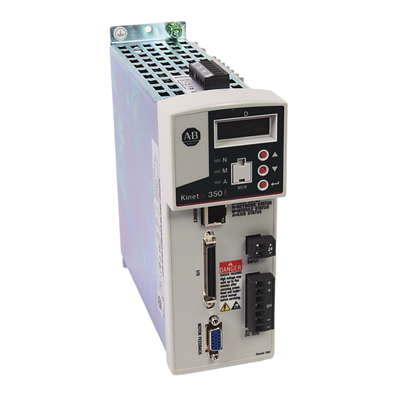
Although the physical size of the Kinetix® 350 drives vary, the location of the connectors and indicators is identical. and Indicators Figure 10 - Kinetix 350 Drive Connector and Indicators 3 5 0 Kinetix 350 Drive, Top View Kinetix® 350 Drive, Front View... -
Page 35: Safe Torque-Off Connector Pinout
Safe Torque-off Connector Pinout The Kinetix 350 drive ships with the (6-pin) wiring-plug header that connects your safety circuit to the Kinetix 350 drive safe torque-off (STO) connector. If your system does not use the safe torque-off feature, follow instructions in... -
Page 36: I/O Connector Pinout
Chapter 3 Kinetix 350 Drive Connector Data I/O Connector Pinout IOD Pin Description Signal 1…25 Reserved Reserved +/- Overtravel, enable, and home common Negative hardware overtravel NEG_OT Positive hardware overtravel POS_OT Drive enable ENABLE Home switch HOME_SW 31…35 Reserved —... -
Page 37: Motor Feedback (Mf) Connector Pinout
Kinetix 350 Drive Connector Data Chapter 3 Motor Feedback (MF) Connector Pinout MF Pin Description Signal MF Pin Description Signal Sine differential input+ SIN+ Reserved — AM+ differential input+ Sine differential input- SIN- Data differential input - DATA- AM- differential input-... -
Page 38: Ac Input Power Connector Pinout
Chapter 3 Kinetix 350 Drive Connector Data AC Input Power Connector Pinout Description Description Signal Signal Designator (2097-V31PRx-LM drives) Designator (2097-V32PRx-LM drives) L2/N AC power in (non-doubler operation) L2/N AC power in AC power in AC power in AC power neutral (only 120V doubler) -
Page 39: Control Signal Specifications
Kinetix 350 Drive Connector Data Chapter 3 Control Signal Specifications This section provides a description of the Kinetix 350 drive I/O (IOD), communication, shunt resistor and DC bus (BC), and back-up power (BP) connectors. Digital Inputs Five fixed inputs are available for the machine interface on the Kinetic 350 drive. - Page 40 Chapter 3 Kinetix 350 Drive Connector Data Table 15 - Understanding Digital Input Functions Function Description Behavior If the controller configuration specifies checking of the enable input, an By default drive enable input checking is enabled. If the checking is...
- Page 41 Kinetix 350 Drive Connector Data Chapter 3 Figure 15 - Sourcing of Digital Inputs +24V 1.2 kΩ ENABLE, HOME_SW, POS_OT, or NEG_OT 1.2 kΩ ENABLE, HOME_SW, POS_OT, or NEG_OT Figure 16 - Sinking of Digital Inputs 1.2 kΩ ENABLE, HOME_SW, POS_OT, or NEG_OT 1.2 kΩ...
-
Page 42: Motor Brake Output
Chapter 3 Kinetix 350 Drive Connector Data Figure 17 - Sourcing of Registration Digital Input 1.2 kΩ +24V 1.2 kΩ REG_COM Figure 18 - Sinking of Registration Digital Input 1.2 kΩ 1.2 kΩ REG_COM +24V Motor Brake Output The two digital outputs (IOD-43 and IOD-44) have fixed pin assignments for motor brake function. -
Page 43: Ethernet Communication Specifications
(328 ft), max 24V DC Back-up Power Specifications The Kinetix 350 drive can use an external power supply to power the logic and communication circuits. If an independent 24V (@ 1 A) power supply is connected to the BP connector, the logic and communication circuits remain active during a mains input power loss. -
Page 44: Motor Feedback Specifications
Single-ended, under 500 Ω = no fault, over Thermostat 10 kΩ = fault The Kinetix 350 drives support multiple types of feedback devices by using the 15-pin (MF) motor feedback connector and shared connector pins in many cases. Table 18 - Motor Feedback Signals by Device Type... - Page 45 Kinetix 350 Drive Connector Data Chapter 3 Figure 20 is the motor thermostat interface schematic. Although the thermostat signal is shown for all feedback types, some motors do not support this feature because it is not part of the feedback device.
- Page 46 Chapter 3 Kinetix 350 Drive Connector Data Table 20 - Stegmann Hiperface Specifications Attribute Value Protocol Hiperface Memory support Not programmed, or programmed with Allen-Bradley® motor data Hiperface data communication RS485, 9600 bps, 8 data bits, no parity Sine/Cosine interpolation...
- Page 47 Kinetix 350 Drive Connector Data Chapter 3 Table 21 - Generic TTL Incremental Specifications Attribute Value TTL incremental encoder support 5V, differential A quad B Quadrature interpolation 4 counts/square wave period Differential input voltage 1.0…7.0V (AM, BM, and IM) DC current draw...
- Page 48 Chapter 3 Kinetix 350 Drive Connector Data Figure 24 - Generic TTL Interface, IM Signals 10 kΩ 1 kΩ MTR_IM+ to AqB Counter 1 kΩ MTR_IM- 56 pF 56 pF 10 kΩ Shaded area indicates components that are part of the circuit, but support other feedback device types (not used for Generic TTL incremental support).
-
Page 49: Feedback Power Supply
Kinetix 350 Drive Connector Data Chapter 3 Feedback Power Supply The Kinetix 350 drive generates +5V and +9V DC for motor feedback power. Short circuit protection and separate common mode filtering for each channel is included. Table 23 - Motor Feedback Power Specifications... - Page 50 Chapter 3 Kinetix 350 Drive Connector Data Notes: Rockwell Automation Publication 2097-UM002D-EN-P - April 2017...
-
Page 51: Basic Wiring Requirements
Chapter Connect the Kinetix 350 Drive System Topic Page Basic Wiring Requirements Grounding Your Kinetix 350 Drive System Power Wiring Requirements Wiring Guidelines Wiring the Kinetix 350 Drive Connectors Apply the Motor Cable Shield Clamp Feedback and I/O Cable Connections... -
Page 52: Recommended Cables
Noise Reference Manual, publication GMC-RM001, for more information. Determine the Input Power This section contains examples of typical single-phase and three-phase facility input power that is wired to single-phase and three-phase Kinetix 350 drives. Configuration The grounded power configuration lets you ground your single-phase or three- phase power at a neutral point. -
Page 53: Three-Phase Power Wired To Three-Phase Drives
Ground Grid or Power Distribution Ground ATTENTION: For the 480V Kinetix 350 drives to meet proper voltage creepage and clearance requirements, each phase voltage to ground must be less than or equal to 300V AC rms. This requirement means that the power system must use a center grounded wye secondary configuration for 400/ 480V AC mains. -
Page 54: Single-Phase Power Wired To Single-Phase Drives
To use the voltage-doubler circuit, connect the 120V single-phase input power to the IPD-L1 and IPD-N terminals. For Kinetix 350 drive power specifications, refer to Kinetix Servo Drives Specifications Technical Data, publication KNX-TD003. For Kinetix 350... -
Page 55: Isolation Transformer In Grounded Power Configurations
Three-phase Power Wired to Single-phase Drives This example illustrates grounded three-phase power that is wired to single- phase Kinetix 350 drives when phase-to-phase voltage is within drive specifications. Figure 31 - Single-phase Amplifiers on Three-phase Power (WYE) 2097-V32PRx-LM... - Page 56 Connect the Kinetix 350 Drive System This example illustrates grounded three-phase power that is wired to single- phase Kinetix 350 drives when phase-to-phase voltage exceeds drive specifications. A neutral must be connected when single-phase drives are attached to a three- phase isolating transformer secondary.
-
Page 57: Voiding Of Ce Compliance
Connect the Kinetix 350 Drive System Chapter 4 Voiding of CE Compliance The three-phase and neutral in-line filter applications that are described Three- phase Power Wired to Single-phase Drives on page 55 are not adequate for CE compliance for EMC. Therefore, EMC validity and CE marking by Rockwell Automation is voided when three-phase and neutral in line filters are used. -
Page 58: Grounding Your Kinetix 350 Drive System
Kinetix 350 drive. If the Kinetix 350 drive is mounted on a painted subpanel, ground the drive to a bonded cabinet ground bus by using a braided ground strap or 4.0 mm2 (12 AWG) solid copper wire 100 mm (3.9 in.) long. -
Page 59: Ground Multiple Subpanels
Connect the Kinetix 350 Drive System Chapter 4 Figure 34 - Chassis Ground Configuration (Multiple Kinetix 350 Drives on One Panel) Chassis Ground Chassis Ground Chassis Ground Chassis Ground Bonded Ground Bar (optional) Bonded Cabinet Ground Grid or Power Ground Bus... -
Page 60: Power Wiring Requirements
Power Wiring Examples page 131 for interconnect diagrams. IMPORTANT The National Electrical Code and local electrical codes take precedence over the values and methods provided. Table 24 - Kinetix 350 Drive Power Wiring Requirements Terminals Recommended Wire Size Strip Length Torque Value Cat. -
Page 61: Wiring Guidelines
IMPORTANT To improve system performance, run wires and cables in the wireways as established in Establish Noise Zones page Follow these steps when wiring the connectors on your Kinetix 350 drive modules. 1. Prepare the wires for attachment to each connector plug by removing insulation equal to the recommended strip length. -
Page 62: Wiring The Kinetix 350 Drive Connectors
Chapter 4 Connect the Kinetix 350 Drive System Wiring the Kinetix 350 Drive This section provides examples and wiring tables to assist you when you make connections to the Kinetix 350 drive. Connectors Wire the Safe Torque-off (STO) Connector For the safe torque-off (STO) connector pinouts, feature descriptions, and... -
Page 63: Wire The Input Power (Ipd) Connector
Connect the Kinetix 350 Drive System Chapter 4 Wire the Input Power (IPD) Connector Kinetix 350 Drive Table 26 - Input Power (IPD) Connector Recommended Strip Length Torque Value Drive Cat. No. Terminals Wire Size mm (in.) N•m (lb•in) mm² (AWG) -
Page 64: Wire The Motor Power (Mp) Connector
Chapter 4 Connect the Kinetix 350 Drive System Wire the Motor Power (MP) Connector Connections to the motor power (MP) connector include rotary motors and rotary motor driven actuators. Kinetix 350 Drive Bottom View Table 27 - Motor Power (MP) Termination Specifications... - Page 65 Connect the Kinetix 350 Drive System Chapter 4 Pigtail Terminations TL-Series motors have a short pigtail cable that connects to the motor, but is not shielded. The preferred method for grounding the TL-Series power cable on the motor side is to expose a section of the cable shield and clamp it directly to the machine frame.
- Page 66 Chapter 4 Connect the Kinetix 350 Drive System This diagram shows an example of three-phase power wires for motors/ actuators that have no brakes. Thermal switch wires are included in the feedback cable. Kinetix 350 Drive/Rotary Motor Wiring Examples that start on page 134 for interconnect diagrams.
- Page 67 Connect the Kinetix 350 Drive System Chapter 4 This diagram shows an example of wiring with three-phase power wires and brake wires. The brake wires have a shield braid that is shown in Figure 38 gray, which folds back under the cable clamp before the conductors are attached to the motor brake circuit.
- Page 68 Chapter 4 Connect the Kinetix 350 Drive System Cable shield and lead preparation are provided with most Allen-Bradley® cable assemblies. Follow these guidelines if your motor power cable shield and wires require preparation. Figure 39 - Cable Shield and Lead Preparation...
-
Page 69: Apply The Motor Cable Shield Clamp
5. Clamp the exposed shield to the panel by using the clamp and two #6-32 x 1 screws provided. 6. Repeat step 1…step 5 for each Kinetix 350 drive you are installing. Rockwell Automation Publication 2097-UM002D-EN-P - April 2017... -
Page 70: Feedback And I/O Cable Connections
Chapter 4 Connect the Kinetix 350 Drive System Feedback and I/O Cable Factory made cables with premolded connectors are designed to minimize EMI and are recommended over hand-built cables to improve system Connections performance. However, other options are available for building your own feedback and I/O cables. -
Page 71: Flying-Lead Feedback Cable Pin-Outs
Connect the Kinetix 350 Drive System Chapter 4 Flying-lead Feedback Cable Pin-outs Table 33 - 2090-XXNFMF-Sxx or 2090-CFBMxDF-xxAxxx Feedback Cable Incremental High-resolution Feedback Drive MF Feedback Connector Pin Connector Pin 9V Encoder 5V Encoder 5V Encoder Sin+ Sin+ Sin- Sin-... -
Page 72: Wiring The Feedback And I/O Connectors
Chapter 4 Connect the Kinetix 350 Drive System Wiring the Feedback and I/O These procedures assume that you have mounted your Kinetix 350 system, completed the power wiring, and are ready to connect motor feedback. Connectors Wire the I/O Connector Connect your I/O wires to the IOD connector by using the 2097-TB1 I/O Terminal Expansion Block. -
Page 73: Wire The Low-Profile Connector Kit
Wire the Low-profile Connector Kit The 2090-K2CK-D15M low-profile connector kit is suitable for terminating flying-lead motor feedback cables. Use it with the Kinetix 350 drive and all motors with incremental or high-resolution feedback. It has a 15-pin, male, D- sub connector and is compatible with all Bulletin 2090 feedback cables. -
Page 74: Shunt Resistor Connections
0.5 (4.5) Ethernet Cable Connections This guideline assumes that you have your Logix5000™ Ethernet/IP module and Kinetix 350 drive that is mounted and ready to connect the network cables. IMPORTANT Connection to a larger network through an unmanaged switch without Internet Group Management Protocol Snooping could cause degradation to the larger network. - Page 75 The Ethernet ports are on bottom of controller. The Port 1 Ethernet connection is used for connecting to a Logix5000™ controller and to configure your Kinetix 350 drive. Figure 45 - Ethernet Wiring Example - External Switch CompactLogix Controller Platform...
- Page 76 Chapter 4 Connect the Kinetix 350 Drive System Notes: Rockwell Automation Publication 2097-UM002D-EN-P - April 2017...
- Page 77 Kinetix 350 Drive System Topic Page Keypad Input Configure the Kinetix 350 Drive Ethernet IP Address Configure the Logix5000 EtherNet/IP Controller Apply Power to the Kinetix 350 Drive Test and Tune the Axes Disable EnableInputChecking by Using a Logix Designer Message Instruction TIP Before you begin make sure that you know the catalog number for the drive, the Logix5000™...
-
Page 78: Keypad Input
Chapter 5 Configure and Start up the Kinetix 350 Drive System Keypad Input The Kinetix® 350 drive is equipped with a diagnostic status indicator and three push buttons that are used to select displayed information and to edit a limited set of parameter values. -
Page 79: Status Indicators
Configure and Start up the Kinetix 350 Drive System Chapter 5 Status Indicators The Kinetix 350 drive has four status indicators and a four-digit display on the top front panel as shown Figure 46. These status indicators and the display are used to monitor the system status, activity, and troubleshoot faults. - Page 80 Chapter 5 Configure and Start up the Kinetix 350 Drive System Table 39 - Axis State Status Indicator Status Indicator State Flash red/green Self test Initialization - bus not up Flashing green Initialization - bus up Shutdown - bus not up...
-
Page 81: Configure The Kinetix 350 Drive Ethernet Ip Address
Kinetix 350 Drive Ethernet Port Configuration The IP address of the Kinetix 350 drive is composed of four suboctets that are separated by three dots to conform to the Class C Subnet structure. Each suboctet can be configured with number from 1 to 254. As shipped from the factory the default IP address of a drive is 192.168.124.200. -
Page 82: Configure The Ip Address Manually (Static Address)
When connecting directly from the Kinetix 350 drive to the personal computer without a server or when connecting to a private network, where all devices have static IP addresses, assign the IP address of the Kinetix 350 drive manually. To assign the address manually, disable the DHCP mode. Do following the steps by using the drive keypad. -
Page 83: Configure The Ip Address Automatically (Dynamic Address)
5. Cycle power to the drive to make this change take effect. When the Kinetix 350 drive is waiting for an IP address to be assigned to it by the server it displays ‘----‘ in each of the four octet parameters (IP_1, IP_2, IP_3, and IP_4) on its display. -
Page 84: Configure The Logix5000 Ethernet/Ip Controller
Chapter 5 Configure and Start up the Kinetix 350 Drive System Configure the Logix5000 This procedure assumes that you have wired your Kinetix 350 drive system and are using Logix Designer application version 21.00.00 or later. EtherNet/IP Controller For help using Logix Designer application as it applies to the configuration of the ControlLogix®... - Page 85 Configure and Start up the Kinetix 350 Drive System Chapter 5 The New Controller dialog box appears. 4. Configure the new controller. a. From the Type pull-down menu, choose the controller type. b. From the Revision pull-down menu, choose the revision.
-
Page 86: Configure The Kinetix 350 Drive
9. Click OK. Configure the Kinetix 350 Drive IMPORTANT To configure Kinetix 350 drive (catalog numbers 2097-V3xPRx-LM) you must be using RSLogix 5000® software, version 20 or later, or Logix Designer application. Follow these steps to configure the Kinetix 350 drive. - Page 87 Configure and Start up the Kinetix 350 Drive System Chapter 5 3. Select your 2097-V3xPRx-LM drive as appropriate for your actual hardware configuration and click Create. The New Module dialog box appears. 4. Configure the new drive. a. Enter the drive Name.
- Page 88 Chapter 5 Configure and Start up the Kinetix 350 Drive System The 2097-V3xPRx-LM drive appears under the EtherNet/IP module in the I/O Configuration folder. 9. Right-click the 2097-V3xPRx-LM module that you created and choose Properties. The Module Properties dialog box appears.
-
Page 89: Configure The Motion Group
Configure and Start up the Kinetix 350 Drive System Chapter 5 Configure the Motion Group Follow these steps to configure the motion group. 1. Right-click Motion Groups in the Controller Organizer and choose New Motion Group. The New Tag dialog box appears. -
Page 90: Configure Axis Properties
Chapter 5 Configure and Start up the Kinetix 350 Drive System Configure Axis Properties To configure axis properties for your motor or actuator follow these instructions. If you are using an Integrated Motion Encoder on EtherNet/IP, catalog number 842E-CM for an axis refer to 842E-CM Integrated Motion Encoder on EtherNet/IP User Manual, publication 842E-UM002. - Page 91 Configure and Start up the Kinetix 350 Drive System Chapter 5 7. Click Apply. Motor data specific to your motor appears in the Motor category. 8. Click the Scaling category and edit the default values as appropriate for your application.
- Page 92 Chapter 5 Configure and Start up the Kinetix 350 Drive System The Actions to Take Upon Conditions dialog box appears. From this dialog box, you can program actions and change the action for exceptions (faults). 13. Click Parameters. The Motion Axis Parameters dialog box appears.
-
Page 93: Download The Program
Mains input power Apply 120, 240, or 460V AC mains input power to the drive (IPD connector). 3. Apply 120, 240, or 460V AC mains input power to the Kinetix 350 drive IPD connector. 4. Observe the four-digit status indicator. -
Page 94: Test And Tune The Axes
If drive ENABLE is Then Hard wired Apply 24V DC Not used Disable enableInputChecking by using procedure on page 100 7. Observe the status indicator on the front of the Kinetix 350 drive. Status Indicator Condition Status Do This Steady green Operational condition... - Page 95 Configure and Start up the Kinetix 350 Drive System Chapter 5 3. Click Hookup Tests category. 4. Type 2.0 as the number of revolutions for the test or another number more appropriate for your application. This Test Performs this Test...
- Page 96 Chapter 5 Configure and Start up the Kinetix 350 Drive System The RSLogix 5000 - Motor and Feedback Test dialog box appears. The Test State is Executing. When the test completes successfully, the Test State changes from Executing to Passed.
-
Page 97: Tune The Axes
Configure and Start up the Kinetix 350 Drive System Chapter 5 Tune the Axes The following is a basic procedure for simple systems. If you have a complicated system, see Integrated Motion on the EtherNet/IP Network: Configuration and Startup, publication... - Page 98 Chapter 5 Configure and Start up the Kinetix 350 Drive System If drive ENABLE is Then Hard wired Apply 24V DC Not used Disable enableInputChecking by using procedure on page 100 ATTENTION: To avoid personal injury or damage to equipment, apply only 24V ENABLE signal to the axis you are testing.
- Page 99 Configure and Start up the Kinetix 350 Drive System Chapter 5 11. If the test fails, this dialog box appears. a. Click OK. b. Make motor velocity adjustments. c. See the appropriate Logix5000 motion module user manual for more information.
-
Page 100: Disable Enableinputchecking By Using A Logix
Chapter 5 Configure and Start up the Kinetix 350 Drive System Disable EnableInputChecking This procedure sends a Logix5000 message to disable the EnableInputChecking attribute in the Kinetix 350 drive. by Using a Logix Designer Message Instruction 1. From the Controller Organizer, choose Tasks>MainTask>MainProgram>MainRoutine. -
Page 101: Certification
PFD and PFH Data Safe Torque-off Connector Data Wiring Your Safe Torque-off Circuit Kinetix 350 Drive Safe Torque-off Feature Kinetix 350 Drive Safe Torque-off Wiring Diagrams Safe Torque-off Signal Specifications Certification The safe torque-off circuit is type-approved and certified for use in safety applications up to and including ISO 13849-1 performance level d (PLd) safety category 3. -
Page 102: Safety Category 3 Requirements
Chapter 6 Kinetix 350 Drive Safe Torque-off Feature Safety Category 3 Requirements Safety-related parts are designed with these attributes: • A single fault in any of these parts does not lead to the loss of the safety function • A single fault is detected whenever reasonably practicable •... -
Page 103: Troubleshoot The Safe Torque-Off Function
Kinetix 350 Drive Safe Torque-off Feature Chapter 6 ATTENTION: Permanent magnet motors can, if there are of two simultaneous faults in the IGBT circuit, result in a rotation of up to 180 electrical degrees. Troubleshoot the Safe Torque-off Function ATTENTION: When the safe torque-off function is activated, the drive posts a Start Inhibit (Sc05). -
Page 104: Safe Torque-Off Connector Data
Kinetix 350 Drive Safe Torque-off Feature Safe Torque-off Connector This section provides safe torque-off (STO) connector and header information for the Kinetix 350 drive safe torque-off. Data STO Connector Pinouts Headers extend the STO connector signals for use in wiring or to defeat (not use) the safe torque-off function. -
Page 105: Wiring Your Safe Torque-Off Circuit
Kinetix 350 Drive Safe Torque-off Feature Chapter 6 Wiring Your Safe Torque-off This section provides guidelines for wiring your Kinetix 350 safe torque-off drive connections. Circuit European Union Directives If this product is installed within the European Union or EEC regions and has the CE mark, the following regulations apply. -
Page 106: Safe Torque-Off Wiring Requirements
Chapter 6 Kinetix 350 Drive Safe Torque-off Feature Safe Torque-off Wiring Requirements The following are the safe torque-off (STO) wiring requirements. The wire must be copper with 75 °C (167 °F) minimum rating. IMPORTANT The National Electrical Code and local electrical codes take precedence over the values and methods provided. -
Page 107: Kinetix 350 Drive Safe Torque-Off Feature
Kinetix 350 Drive Safe Torque-off Feature Chapter 6 Kinetix 350 Drive Safe The safe torque-off circuit, when used with suitable safety components, provides protection according to EN ISO 13849-1 (PLd). The safe torque-off Torque-off Feature option is just one safety control system. All components in the system must be chosen and applied correctly to achieve the desired level of operator safeguarding. -
Page 108: Kinetix 350 Drive Safe Torque-Off Wiring Diagrams
IMPORTANT The Kinetix 350 drive meets the requirements of EN ISO 13849-1 Safety of Machinery, Safety-related Parts of Control Systems, category (CAT 3), performance level (PL)d and Safety Integrity Level (SIL) 2 per EN 61800-5- 2:2007. -
Page 109: Safe Torque-Off Signal Specifications
Kinetix 350 Drive Safe Torque-off Feature Chapter 6 Figure 51 - Single-axis Relay Configuration (Stop Category 0) with Manual Reset External +24V External 24V COM Allen-Bradley Monitoring Safety Relay MSR127RP (440R-N23135) 440R-D22R2 Kinetix 350 Drive Auxiliary Signal Safe Torque-off to PLC... -
Page 110: Safety Input And Output Schematics
Chapter 6 Kinetix 350 Drive Safe Torque-off Feature Safety Input and Output The following are generic safety input and output schematics for the Kinetix 350 drive. Schematics Figure 52 - Safety Input Safety Input 1/2 STO-4/6 Safety COM STO-5 SAFETYCOM... -
Page 111: Safety Precautions
Chapter Troubleshoot the Kinetix 350 Drive Topic Page Safety Precautions Interpret Status Indicators General System Behavior Logix5000 Controller and Drive Behavior Web Server Interface Safety Precautions Observe the following safety precautions when troubleshooting your Kinetix® 350 drive. ATTENTION: Capacitors on the DC bus can retain hazardous voltages after input power has been removed. -
Page 112: Interpret Status Indicators
Chapter 7 Troubleshoot the Kinetix 350 Drive Interpret Status Indicators See these troubleshooting tables to identify faults, potential causes, and the appropriate actions to resolve the fault. If the fault persists after attempting to troubleshoot the system, please contact your Rockwell Automation sales representative for further assistance. -
Page 113: Error Codes
Troubleshoot the Kinetix 350 Drive Chapter 7 Error Codes The following list helps you resolve memory anomalies. When a fault is detected, the status indicator displays an E and a two-digit error code until the anomaly is cleared. Error Anomaly... - Page 114 Chapter 7 Troubleshoot the Kinetix 350 Drive Table 45 - S xx and Scxx Start Inhibit Codes (Continued) RSLogix 5000® and Logix Four-digit Display Problem or Symptom Potential Cause Possible Resolution Designer Fault Message The associated motor has not been S 02 Motor not configured.
- Page 115 Potential Cause Possible Resolution Designer Fault Message Drive fan failed. Replace the failed drive. Check the cabinet temperature. See Kinetix 350 Drive Power Specifications in The cabinet ambient temperature Kinetix Servo Drives Specifications is above rating. Technical Data, publication KNX-TD003...
- Page 116 Chapter 7 Troubleshoot the Kinetix 350 Drive Table 46 - F xx Fault Codes (Continued) RSLogix 5000 and Logix Four-digit Display Problem or Symptom Potential Cause Possible Resolution Designer Fault Message Check all wiring at motor feedback (MF) Partial loss of feedback signals.
- Page 117 Troubleshoot the Kinetix 350 Drive Chapter 7 Table 48 - Ic xx Fault Codes RSLogix 5000 and Logix Four-digit Display Problem or Symptom Potential Cause Possible Resolution Designer Fault Message The motor data that is stored in a smart encoder •...
- Page 118 Chapter 7 Troubleshoot the Kinetix 350 Drive Table 51 - nF xx Fault Codes RSLogix 5000 and Logix Four-digit Display Problem or Symptom Potential Cause Possible Resolution Designer Fault Message • Remove unnecessary network devices from the motion network. •...
-
Page 119: Status Indicators
Troubleshoot the Kinetix 350 Drive Chapter 7 Status Indicators Table 52 - Drive Status Indicator Status Description No power. Apply power. Alternating green/red Self-test (power-up diagnostics). Wait for steady green. Flashing green Standby (device not configured). Wait for steady green. -
Page 120: General System Behavior
Chapter 7 Troubleshoot the Kinetix 350 Drive Table 54 - Network Status Indicators Status Description No power or no IP address defined. Alternating green/red Self-test mode (power-up diagnostics). Flashing green Standby (device that is not configured, or connection not established). - Page 121 Troubleshoot the Kinetix 350 Drive Chapter 7 Table 56 - General System Behavior (Continued) Condition Potential Cause Possible Resolution Torque Limit limits are set too low. Verify that current limits are set properly. Select the correct motor and run Tune in Logix Designer Incorrect motor that is selected in configuration.
- Page 122 Chapter 7 Troubleshoot the Kinetix 350 Drive Table 56 - General System Behavior (Continued) Condition Potential Cause Possible Resolution Torque Limit limits are set too low. Verify that current limits are set properly. Select the correct motor and run Tune in Logix Designer Incorrect motor that is selected in configuration.
- Page 123 Troubleshoot the Kinetix 350 Drive Chapter 7 Table 56 - General System Behavior (Continued) Condition Potential Cause Possible Resolution Motor tuning limits are set too high. Run Tune in RSLogix 5000 software. • Remove the loose parts. Loose parts are present in the motor.
-
Page 124: Logix5000 Controller And Drive Behavior
IMPORTANT The fault detection ability of TTL encoders is not as advanced as with Stegmann hiperface or Tamagawa 17-bit serial encoders. When a TTL encoder loses its A/B signals, the Kinetix 350 drive is unable to detect this fault directly. Instead it relies on a secondary fault to detect the condition, typically excessive position or velocity error. - Page 125 Motor Thermal Overload that is given by Motor Thermal Overload Factory Limit. This limit is 108 °C Decel/Disable (226 °F) for the Kinetix 350 drive. Inverter current has exceeded the factory set peak or instantaneous current F 10 Inverter Overcurrent Disable/Coast limit.
- Page 126 IMPORTANT The fault detection ability of TTL encoders is not as advanced as with Stegmann Hiperface or Tamagawa 17-bit serial encoders. When a TTL encoder loses its A/B signals, the Kinetix 350 drive is unable to detect this fault directly. Instead it relies on a secondary fault to detect the condition, typically excessive position or velocity error.
- Page 127 Troubleshoot the Kinetix 350 Drive Chapter 7 Table 59 - Drive Behavior, Fcxx Custom Fault Codes (Continued) Best Stopping Method Four-digit Display Exception Description (Only Major Fault) Current in one or more phases have been lost or remains below a preset...
-
Page 128: Web Server Interface
Troubleshoot the Kinetix 350 Drive Web Server Interface The Kinetix 350 drive supports a basic web interface for common status reporting and network configuration attributes. No attributes are configurable from this page. To access the page, open a web browsers program and enter the IP address of the drive. - Page 129 Appendix Interconnect Diagrams Topic Page Interconnect Diagram Notes Power Wiring Examples Kinetix 350 Drive/Rotary Motor Wiring Examples Kinetix 350 Drive/Actuator Wiring Examples Motor Brake Currents System Block Diagrams Rockwell Automation Publication 2097-UM002D-EN-P - April 2017...
-
Page 130: Interconnect Diagram Notes
Place the AC (EMC) line filters as close to the drive as possible and do not route very dirty wires in the wireway. If routing in wireway is unavoidable, use shielded cable with shields that are grounded to the drive chassis and filter case. For AC line filter specifications, refer to Kinetix 350 Drive Power Specifications in Kinetix Servo Drives Specifications Technical Data, publication KNX-TD003.This filter does not apply to 2097-V32PRx-LM drives because they have integrated AC line filters. -
Page 131: Power Wiring Examples
In this example, the 2097-V31PRx-LM drives are wired to use the voltage doubling circuit. The 120V input voltage provides 240V output to motors. The 2097-V33PRx-LM drives are wired for single-phase 120V operation. Figure 57 - Kinetix 350 Drive (120V Single-phase Input Power) 2097-V31PRx -LM and See table on page 130 for note information. - Page 132 Appendix A Interconnect Diagrams Figure 58 - Kinetix 350 Drives (240V Single-phase Input Power) 2097-V31PRx-LM, 2097-V32PRx-LM See table on page 130 for note information. 2097-V33PRx-LM and Kinetix 350 Drive Ground Stud Bonded Cabinet Ground Bus * 2097-V31PRx-LM 2097-V32PRx-LM Mains AC Line Filter...
-
Page 133: Shunt Resistor Wiring Example
Note 8 * Indicates User Supplied Component IMPORTANT For the 480V Kinetix 350 drives to meet EN ISO 13849-1 (PLd) spacing requirements, each phase voltage to ground must be less than or equal to 300V AC rms. This requirement means that the power system must use center grounded wye secondary configuration for 400/480V AC mains. -
Page 134: Kinetix 350 Drive/Rotary Motor Wiring Examples
Appendix A Interconnect Diagrams Kinetix 350 Drive/Rotary These wiring diagrams apply to Kinetix 350 drives with compatible rotary motors. Motor Wiring Examples IMPORTANT The MP-Series™ motor wiring examples on this page apply to motors equipped with circular DIN (threaded) connectors. - Page 135 DIN (SpeedTec) connectors. Figure 62 - MP-Series (Bulletin MPL-A/B, MPM-A/B, MPF-A/B, and MPS-A/B) Motors MPL-A/B15xxx…MPL-A/B45xxx 2097-V3xPRx-LM See table on page 130 for note information. Kinetix 350 Drives MPM-A/Bxxx, MPF-A/Bxxx Servo Motors with 2090-K2CK-D15M High-Resolution Feedback Connector Kit SHIELD...
- Page 136 Appendix A Interconnect Diagrams Figure 63 - Kinetix 350 Drive with TL-Series™ (TLY-A) Motors See table on page 130 for note information. 2097-V3xPRx-LM TLY-Axxxx-H (230V) Kinetix 350 Drives Servo Motors with 2090-CPBM6DF-16AAxx Incremental Feedback Motor Power and Brake Cable Notes 9, 10 Use 2090-CPWM6DF-16AAxx cable for non-brake applications.
-
Page 137: Kinetix 350 Drive/Actuator Wiring Examples
Appendix A Kinetix 350 Drive/Actuator These wiring diagrams apply to Kinetix 350 drives with compatible linear actuators. Wiring Examples Figure 64 - Kinetix 350 Drive with MP-Series (Bulletin MPAS-A/B) Linear Stages 2097-V3xPRx-LM MPAS-A/Bxxxxx-VxxSxA See table on page 130 for note information. - Page 138 Appendix A Interconnect Diagrams Figure 65 - Kinetix 350 Drive with MP-Series (Bulletin MPAR and MPAI) Electric Cylinders 2097-V3xPRx-LM MPAR-A/Bxxxxx-xxx See table on page 130 for note information. Kinetix 350 Drives and MPAI-A/Bxxx MP-Series Electric Cylinder Power Electric Cylinder with...
- Page 139 Interconnect Diagrams Appendix A Figure 66 - Kinetix 350 Drive with TL-Series (Bulletin TLAR) Electric Cylinders 2097-V3xPRx-LM TLAR-Axxxxx-B (230V) See table on page 130 for note information. Kinetix 350 Drives Servo Motors with 2090-CPBM6DF-16AAxx High-Resolution Feedback Motor Power and Brake Cable...
-
Page 140: Motor Brake Currents
Interconnect Diagrams Motor Brake Currents Use these coil current values to size the interposing relay that is required for your application. See the interconnect diagram for your Kinetix 350 drive/ motor beginning on page 134 for typical motor brake circuitry. See Kinetix... -
Page 141: System Block Diagrams
Interconnect Diagrams Appendix A System Block Diagrams This power block diagram applies to 2097-V32PRx-LM, 2097-V33PRx-LM, and 2097-V34PRx-LM, servo drives. Figure 67 - Power Block Diagram Rockwell Automation Publication 2097-UM002D-EN-P - April 2017... - Page 142 Appendix A Interconnect Diagrams This power block diagram applies to 2097-V31PRx-LM, servo drives. The voltage-doubler circuitry lets the drives with 120V input power get full performance from 240V motors. Figure 68 - Voltage Doubler Block Diagram Rockwell Automation Publication 2097-UM002D-EN-P - April 2017...
-
Page 143: Before You Begin
8.00.017 or later Catalog numbers of the targeted Kinetix® 350 drive you want to upgrade. Network path to the targeted Kinetix 350 drive module you want to upgrade. (1) Download the ControlFLASH kit from http://support.rockwellautomation.com/controlflash. Contact Rockwell Automation Technical Support at (440) 646-5800 for assistance. -
Page 144: Configure Logix5000 Communication
Appendix B Upgrade the Kinetix 350 Drive Firmware Configure Logix5000 This procedure assumes that your are communicating to the Logix5000 controller by using the Ethernet protocol. It is also assumed that your Logix5000 Communication Ethernet module has already been configured. -
Page 145: Upgrade Firmware
Upgrade the Kinetix 350 Drive Firmware Appendix B 6. Click OK. The Configure driver dialog box appears. 7. Type the IP address of your drive. 8. Click OK. The new Ethernet driver appears under Configured Drivers. 9. Click Close. 10. Minimize the RSLinx application dialog box. - Page 146 Appendix B Upgrade the Kinetix 350 Drive Firmware The Welcome to ControlFLASH dialog box appears. 2. Click Next. The Catalog Number dialog box appears. Rockwell Automation Publication 2097-UM002D-EN-P - April 2017...
- Page 147 Upgrade the Kinetix 350 Drive Firmware Appendix B 3. Select your drive module and click Next. The Select Device to Update dialog box appears. 4. Expand your Ethernet node, Logix5000 backplane, and EtherNet/IP network module. 5. Select the servo drive and click OK.
- Page 148 Appendix B Upgrade the Kinetix 350 Drive Firmware 7. Confirm the drive catalog number and firmware revision and click Finish This ControlFLASH warning dialog box appears. 8. Click Yes (when ready). The Progress dialog box appears and upgrading begins. The drive four-digit status indicator changes to -PS- and scrolls IP address, which indicates that upgrading is in progress.
-
Page 149: Verify The Firmware Upgrade
Upgrade the Kinetix 350 Drive Firmware Appendix B 10. The Update Status dialog box appears and indicates success or failure as described here. Upgrading Status Success 1. Update complete appears in a GREEN Status dialog box. 2. Go to step Failure 1. - Page 150 Appendix B Upgrade the Kinetix 350 Drive Firmware The Device Properties dialog box appears. 15. Verify the new firmware revision level. 16. Click Close. Rockwell Automation Publication 2097-UM002D-EN-P - April 2017...
- Page 151 Appendix Leakage Current Specifications This appendix contains a table of the leakage currents to be expected for center, wye, and delta corner-grounded Kinetix® 350 drives used with or without mains filters. Rockwell Automation Publication 2097-UM002D-EN-P - April 2017...
- Page 152 Appendix C Leakage Current Specifications Rockwell Automation Publication 2097-UM002D-EN-P - April 2017...
- Page 153 Leakage Current Specifications Appendix C Rockwell Automation Publication 2097-UM002D-EN-P - April 2017...
- Page 154 Appendix C Leakage Current Specifications Notes: Rockwell Automation Publication 2097-UM002D-EN-P - April 2017...
-
Page 155: Index
120/240V single-phase input power 132 user responsibilities 101 120V single-phase input power 131 circuit breaker 240/480V three-phase input power 133 selection 18 circuit breaker specifications Kinetix 350 19 clamp 69 AC input power clean zone 27 pinouts 38 clearance requirements 23 actions tab 91... - Page 156 18 2097 with MPAS actuator 137 fuse specifications 2097 with MPL/MPM/MPF/MPS motor 134 2097 with TLAR actuator 139 Kinetix 350 19 2097 with TLY motor 136 240/480V three-phase input power 133 notes 130 shunt resistor 133 generic TTL incremental 44...
- Page 157 94 safety products catalog 108 tune 94 shield clamp 69 velocity 121 mount shunt resistor 30 Kinetix 350 drive 32 interconnect diagram 133 MSG instruction 100 wiring requirements 74 shunt resistor and DC bus pinouts 38 shunt/DC bus connector 74...
- Page 158 Index determine type 52 low profile connectors 73 Tamagawa 44 motor cable shield clamp 69 test axes motor feedback 70 motor power 65 hookup test 95 requirements 51 transformer drive 60 sizing 20 shunt resistor 74 specifications 21 route power and signal wiring 52 troubleshooting 120 shunt resistor 74 ControlFLASH 149...
- Page 159 Index Notes: Rockwell Automation Publication 2097-UM002D-EN-P - April 2017...
- Page 160 Index Rockwell Automation Publication 2097-UM002D-EN-P - April 2017...
- Page 162 Rockwell Automation Support Use the following resources to access support information. Knowledgebase Articles, How-to Videos, FAQs, Chat, Technical Support Center https://rockwellautomation.custhelp.com/ User Forums, and Product Notification Updates. Local Technical Support Phone http://www.rockwellautomation.com/global/support/get-support- Locate the phone number for your country. now.page Numbers Find the Direct Dial Code for your product.