Table of Contents
Quick Links
Ultra3000
Digital Servo Drives
(Catalog Numbers
2098-DSD-005, -010, and -020
2098-DSD-xxxX
2098-DSD-xxx-SE
2098-DSD-xxx-DN
2098-DSD-xxxX-DN
2098-DSD-030, -075, and -150
2098-DSD-xxxX
2098-DSD-xxx-SE
2098-DSD-xxx-DN
2098-DSD-xxxX-DN
2098-DSD-HV030, -HV050, -HV100, -HV150,
and -HV220
2098-DSD-HVxxxX
2098-DSD-HVxxx-SE
2098-DSD-HVxxx-DN
2098-DSD-HVxxxX-DN)
Installation Manual
Table of Contents
Troubleshooting

Related Manuals for Allen-Bradley 2098-DSD-010


Summary of Contents for Allen-Bradley 2098-DSD-010
- Page 1 Ultra3000 Digital Servo Drives (Catalog Numbers 2098-DSD-005, -010, and -020 2098-DSD-xxxX 2098-DSD-xxx-SE 2098-DSD-xxx-DN 2098-DSD-xxxX-DN 2098-DSD-030, -075, and -150 2098-DSD-xxxX 2098-DSD-xxx-SE 2098-DSD-xxx-DN 2098-DSD-xxxX-DN 2098-DSD-HV030, -HV050, -HV100, -HV150, and -HV220 2098-DSD-HVxxxX 2098-DSD-HVxxx-SE 2098-DSD-HVxxx-DN 2098-DSD-HVxxxX-DN) Installation Manual...
-
Page 2: Notes
IMPORTANT application and understanding of the product. Allen-Bradley, A-B, ControlLogix, and Rockwell Automation are registered trademarks of Rockwell Automation. RSLogix, RSLogix 5000, SoftLogix, and Ultra3000 are trademarks of Rockwell Automation. DeviceNet is a trademark of the Open DeviceNet Vendor Association. - Page 3 Summary of Changes The Ultra3000 Digital Servo Drive Installation Manual Document Update, publication 2098-DU003B-EN-P, includes important information about changes and updates to this Ultra3000 Digital Servo Drive Installation Manual. The document update used to be provided as a separate document, but is now incorporated into this installation manual, in the section immediately following this Summary of Changes section, and before the Table of Contents.
-
Page 4: Notes
Summary of Changes Notes: Rockwell Automation Publication 2098-IN003E-EN-P - March 2012... - Page 5 Document Update Ultra3000 Digital Servo Drive Installation Manual Catalog Numbers 2098-DSD-005, -010, and -020 2098-DSD-xxxX 2098-DSD-xxxSE 2098-DSD-xxx-DN 2098-DSD-xxxX-DN 2098-DSD-030, -075, and -150 2098-DSD-xxxX 2098-DSD-xxxSE 2098-DSD-xxx-DN 2098-DSD-xxxX-DN 2098-DSD-HV030, -HV050, -HV100, -HV150, and -HV220 2098-DSD-xxxX 2098-DSD-xxxSE 2098-DSD-xxx-DN 2098-DSD-xxxX-DN About This Publication This document updates information about the Ultra3000 digital servo drive products.
- Page 6 Ultra3000 Digital Servo Drive Installation Manual Page 2-52 Replace Figure 2.57 on page 2-52 with the one shown below. The new figure correctly identifies the drive connector as CN3. Figure 2.57 RS-232 to RS-485 Connection Diagram +12V dc Common RS-232 232 to 485 Interface Adapter...
- Page 7 Ultraware software, version 1.63, is required to download firmware to Series C drives containing the new power board. Ultra3000 Drive (230V) Power Specifications 2098-DSD-005x-xx, 2098-DSD-010x-xx, and 2098-DSD-020x-xx Description Specification 2098-DSD-005 2098-DSD-010 2098-DSD-020 100...240V rms single-phase AC input voltage AC input frequency 47...63 Hz (2) (3)
- Page 8 Ultra3000 Digital Servo Drive Installation Manual Page A-3 Replace the Ultra3000 (230V) Power Specifications table on page A-3 with the one shown below. The new table includes an updated value in the bus capacitance field for 2098-DSD-030 drives. Ultra3000 Drive (230V) Power Specifications 2098-DSD-030x-xx, 2098-DSD-075x-xx, and 2098-DSD-150x-xx Description Specification...
- Page 9 Ultra3000 Digital Servo Drive Installation Manual Page A-4 Add the attention statement (below) to the Ultra3000 (460V) Power Specifications table on page A-4. The table didn’t change, however, the warning applies to all Ultra3000 drives. Ultra3000 Drive (460V) Power Specifications 2098-DSD-HV030x-xx, -HV050x-xx, -HV100x-xx, -HV150x-xx, and -HV220x-xx Description Specification...
-
Page 10: Figure B
Ultra3000 Digital Servo Drive Installation Manual Page B-2 Replace notes 6 and 7 in the Ultra3000 Interconnect Diagram Notes with the ones shown below. The new versions include information regarding the placement of ac line filters and routing of wires. Note: Information: May be used to maintain power to logic section of drive and status LED indicators when main ac input power is removed. - Page 11 Ultra3000 Digital Servo Drive Installation Manual Page B-5 Replace the interconnect diagram on page B-5 with the one shown below. The new diagram changes the recommended wiring of input fusing, ac line filter, and contactor. Figure B.3 Typical Power Wiring of Ultra3000 System (2098-DSD-075x-xx and -150x-xx) Ultra3000 Digital Servo Drives...
- Page 12 Ultra3000 Digital Servo Drive Installation Manual Page B-6 Replace the interconnect diagram on page B-6 with the one shown below. The new diagram changes the recommended wiring of input fusing, ac line filter, and contactor. Figure B.4 Typical Power Wiring of Ultra3000 System (2098-DSD-HVxxx-xx and -HVxxxX-xx) Ultra3000 Digital Servo Drives...
-
Page 13: Table Of Contents
Ultra3000 Digital Servo Drive Installation Manual Page B-12 Replace Figure B.12 on page B-12 with the one shown below. The new figure includes MP-Series food grade (MPF), stainless steel (MPS) and low inertia (MPL-A/B15xx and MPL-A/B2xx) motors. Also included is an illustration of grounding the feedback cable shield. Figure B.12 Ultra3000 Drive to MP-Series (MPL-A/B, MPF-A/B, and MPS-A/B) Motors MPL-A/B15xx and -A/B2xx,... -
Page 14: Motor Power Cable Note
Ultra3000 Digital Servo Drive Installation Manual Page B-13 Replace Figure B.13 on page B-13 with the one shown below. The new figure correctly identifies the motor brake-connector pins as A and B. Also included is an illustration of grounding the feedback cable shield. -
Page 15: Motor Feedback
Ultra3000 Digital Servo Drive Installation Manual Page B-15 Replace Figure B.15 on page B-15 with the one shown below. The new figure correctly identifies the motor power-cable pins as 1, 2, 3, and 5. Also included is an illustration of grounding the feedback cable shield. - Page 16 (MOV) is recommended to prevent arcing. Use of an MOV can also reduce the time to mechanically engage the brake. Allen-Bradley, Rockwell Automation, and Ultra3000 are trademarks of Rockwell Automation, Inc. Trademarks not belonging to Rockwell Automation are property of their respective companies. Publication 2098-DU003B-EN-P — September...
- Page 17 Conventions Used in this Manual ....P-4 Allen-Bradley Support ......P-4 Local Product Support .
-
Page 18: Thermostat
Table of Contents Analog ILIMIT Input ......2-38 Analog Output ......2-39 Understanding Motor Encoder Feedback Specifications . - Page 19 Table of Contents Chapter 4 Troubleshooting Status Indicators Chapter Objectives....... 4-1 Safety Precautions .
- Page 20 Table of Contents Controlling a Brake Example ..... . B-19 Ultra3000 to Logix Cable and Interconnect Diagrams ..B-20 Ultra3000 to IMC-S Compact Cable and Interconnect Diagram .
-
Page 21: Introduction
Ultra3000. If you do not have a basic understanding of the Ultra3000, contact your local Allen-Bradley representative for information on available training courses before using this product. Purpose of this Manual... - Page 22 Preface Contents of this Manual Refer to the following listing for the descriptive contents of this installation manual. Chapter Title Contents Describes the purpose, background, and scope of Preface this manual. Also specifies the audience for whom this manual is intended. Installing Your Ultra3000 Provides mounting information for the Ultra3000.
-
Page 23: Related Documentation
Preface Related Documentation The following documents contain additional information concerning related Allen-Bradley products. To obtain a copy, contact your local Allen-Bradley office, distributor, or download them from www.theautomationbookstore.com For: Read This Document: Catalog Number: Information on configuring and troubleshooting your... -
Page 24: Conventions Used In This Manual
Ultra3000 with DeviceNet interface Ultra3000-DN Allen-Bradley Support Allen-Bradley offers support services worldwide, with over 75 Sales/ Support Offices, 512 authorized Distributors and 260 authorized Systems Integrators located throughout the United States alone, plus Allen-Bradley representatives in every major country in the world. -
Page 25: Installing Your Ultra3000
ATTENTION installation. The National Electrical Code and any other governing regional or local codes overrule this information. The Allen-Bradley Company cannot assume responsibility for the compliance or the noncompliance with any code, national, local or otherwise, for the proper installation of this system or associated equipment. -
Page 26: Complying With European Union Directives
Directives are available on-line at www.ab.com/certification/ce/ docs. The web site is the authoritative source for verifying compliance and suitability for use of this and other Rockwell Automation/Allen-Bradley products. EMC Directive This unit is tested to meet Council Directive 89/336/EEC Electromagnetic Compatibility (EMC) using a technical construction file and the following standards, in whole or in part: •... -
Page 27: Low Voltage Directive
Installing Your Ultra3000 Low Voltage Directive These units are tested to meet Council Directive 73/23/EEC Low Voltage Directive. The EN 60204-1 Safety of Machinery-Electrical Equipment of Machines, Part 1-Specification for General Requirements standard applies in whole or in part. Additionally, the standard EN 50178 Electronic Equipment for use in Power Installations applies in whole or in part. - Page 28 Installing Your Ultra3000 The typical Ultra3000 system installation includes the following, as shown in the figures below. Figure 1.1 Ultra3000-SE (SERCOS) Digital Servo Drive System Overview RSLogix 5000 Commissioning and Communications Input Output ControlLogix 1756-MxxSE SERCOS Controller Interface Module ControlLogix Chassis SERCOS Fiber-Optic Ring Ultra3000-SE Ultra3000-SE...
-
Page 29: Before Mounting Your System
Installing Your Ultra3000 Figure 1.3 Ultra3000-DN (DeviceNet) Digital Servo Drive System Overview PC-Powered Ultraware Commissioning and Communications Ultra3000-DN Output Input ControlLogix Controller DeviceNet Network Card Encoder Feedback ControlLogix Chassis I/O and Commands DeviceNet Network Motor Power MP-Series Servo Motor Before Mounting Your Before you mount your Ultra3000 system make sure you understand the following: System... -
Page 30: System Mounting Requirements
3% for each additional 300 m (984 ft) up to 3000 m (9842 ft). Consult your local Allen-Bradley representative prior to operating above 3000 m (9842 ft). Plan the installation of your system so that you can... -
Page 31: Ventilation Requirements
Installing Your Ultra3000 Ventilation Requirements This section provides information to assist you in sizing your cabinet and locating your Ultra3000 drive(s) inside the cabinet. Figure 1.4 Minimum Clearance Requirements 50.8 mm (2.0 in.) clearance for airflow and installation Ultra3000 mounted vertically on the panel Do not mount drive on its side. -
Page 32: Sizing An Enclosure
Installing Your Ultra3000 Sizing an Enclosure As an additional aid in sizing an enclosure, with no active method of heat dissipation, either of the following approximate equations can be used: Metric Standard English 0.38Q 4.08Q ----------------------- - ---------------- 1.8T 1.1 –... - Page 33 Installing Your Ultra3000 If you are using the Rockwell Automation/ IMPORTANT Allen-Bradley system sizing program, the average speed and average torque data has already been calculated and can be used in the above equation. If you are not sure of the exact speed and torque in...
-
Page 34: Fuse Sizing
1-10 Installing Your Ultra3000 Fuse Sizing In the United States, the National Electric Code (NEC) specifies that fuses must be selected based on the motor full load amperage (FLA). The typical fuse size should be 300% of the motor FLA for non-time delay fuses (and time-delay class CC fuses) or 175% of motor FLA for time delay fuses. -
Page 35: Bonding Modules
Installing Your Ultra3000 1-11 Bonding Modules Unless specified, most paints are not conductive and they act as insulators. To achieve a good bond between modules and the subpanel, surfaces need to be paint-free or plated. Bonding metal surfaces creates a low-impedance exit path for high-frequency energy. To improve the bond between the drive and IMPORTANT subpanel, construct your subpanel out of zinc plated... -
Page 36: Bonding Multiple Subpanels
1-12 Installing Your Ultra3000 Bonding Multiple Subpanels Bonding multiple subpanels creates a common low impedance exit path for the high frequency energy inside the cabinet. Subpanels that are not bonded together may not share a common low impedance path. This difference in impedance may affect networks and other devices that span multiple panels. -
Page 37: Establishing Noise Zones
Installing Your Ultra3000 1-13 Establishing Noise Zones Observe the following guidelines when laying out your panel (refer to Figure 1.7 for zone locations). • The clean zone (C) is above and beneath the Ultra3000 and includes CN1, CN2, CN3, and the DC filter (grey wireways). •... -
Page 38: Cable Categories For The Ultra3000
1-14 Installing Your Ultra3000 Observe the following guidelines when installing your 1756-MxxSE SERCOS interface module (refer to Figure 1.8 for zone locations). • The clean zone (C) is beneath the less noisy modules (I/O, analog, encoder, registration, etc. (grey wireway). •... -
Page 39: Mounting Guidelines To Reduce Electrical Noise
Installing Your Ultra3000 1-15 The table below indicates the zoning requirements of cables connecting to the External Shunt Resistor Kit. Zone Method Wire/Cable Connector Very Ferrite Shielded Dirty Clean Dirty Sleeve Cable Shunt Connections (shielded option) Shunt Connections (unshielded option) Fan (if present) Mounting Guidelines to Reduce Electrical Noise When mounting an AC line (EMC) filter or external shunt resistor refer... - Page 40 Customer-supplied metal enclosure 150 mm (6.0 in.) of clearance on all sides 1394 Digital Servo Controller of the shunt module 300W Shunt Module Metal conduit ALLEN-BRADLEY BULLETIN 1394 300W SHUNT MODULE minimum CAT. PART SER. INPUT DC INPUT AC FOR FUSE REPLACEMENT USE: (where required by local code) BUSSMAN CAT.
- Page 41 Clean Wireway 150 mm (6.0 in.) of clearance on all sides of the shunt module minimum 1394 Digital Servo Controller 300W Shunt Module ALLEN-BRADLEY BULLETIN 1394 300W SHUNT MODULE CAT. PART SER. INPUT DC INPUT AC FOR FUSE REPLACEMENT USE: BUSSMAN CAT.
-
Page 42: Mounting Your Ultra3000 Drive
If you do not follow ESD control procedures, components can be damaged. If you are not familiar with static control procedures, refer to Allen-Bradley publication 8000-4.5.2, Guarding Against Electrostatic Damage or any other applicable ESD Protection Handbook. -
Page 43: Ultra3000 Connector Data
Chapter Ultra3000 Connector Data Chapter Objectives This chapter provides I/O, encoder, and serial interface connector locations and signal descriptions for your Ultra3000. This chapter includes: • Understanding Ultra3000 Connectors • Understanding Ultra3000 I/O Specifications • Understanding Motor Encoder Feedback Specifications •... -
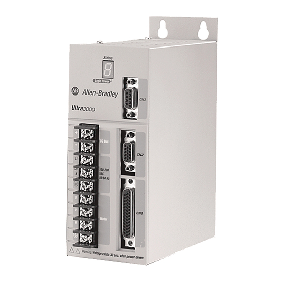
Page 44: Ultra3000 Front Panel Connections
Ultra3000 Connector Data Ultra3000 Front Panel Connections Use the figure below to locate the front panel connections on the Ultra3000 230V drives (500W, 1 kW, and 2 kW). Figure 2.1 Ultra3000 Front Panel Connections for 2098-DSD-005, -005X, -010, -010X, -020, and -020X 9-pin CN3 Serial Connector Pin 5... - Page 45 Ultra3000 Connector Data I/O Connector The following table provides the signal descriptions and pin-outs for the CN1 I/O (44-pin) connector. CN1 Pin Description Signal CN1 Pin Description Signal Auxiliary Encoder Power Out (+5V) EPWR Programmable Analog Output AOUT Common ECOM Analog Current Limit Input ILIMIT Auxiliary Logic Power In (+5V)
- Page 46 Ultra3000 Connector Data Use the figure below to locate the front panel connections on the Ultra3000 230V drives (3 kW). Figure 2.2 Ultra3000 Front Panel Connections for 2098-DSD-030 and -030X 9-pin CN3 Seven Segment Serial Connector Status LED Passive Shunt Internal Logic Power LED Resistor Connections...
- Page 47 Ultra3000 Connector Data I/O Connector The following table provides the signal descriptions and pin-outs for the CN1 I/O (44-pin) connector. CN1 Pin Description Signal CN1 Pin Description Signal Auxiliary Encoder Power Out (+5V) EPWR Programmable Analog Output AOUT Common ECOM Analog Current Limit Input ILIMIT Reserved...
- Page 48 Ultra3000 Connector Data Use the figure below to locate the front panel connections on the Ultra3000 230V (7.5 and 15 kW). Figure 2.3 Ultra3000 Front Panel Connections for 2098-DSD-075, -075X, -150, and -150X 9-pin CN3 Serial Connector Seven Segment Status LED Pin 5 Passive Shunt Pin 9...
- Page 49 Ultra3000 Connector Data I/O Connector The following table provides the signal descriptions and pin-outs for the CN1 I/O (44-pin) connector. CN1 Pin Description Signal CN1 Pin Description Signal Auxiliary Encoder Power Out (+5V) EPWR Programmable Analog Output AOUT Common ECOM Analog Current Limit Input ILIMIT Reserved...
- Page 50 Ultra3000 Connector Data Use the figure below to locate the front panel connections on the Ultra3000 460V drives (3W, 5 kW, 10 kW, 15 kW, and 22 kW). Figure 2.4 Ultra3000 Front Panel Connections for 2098-DSD-HVxxx and HVxxxX Seven Segment Status LED 9-pin CN3 Serial Connector...
- Page 51 Ultra3000 Connector Data I/O Connector The following table provides the signal descriptions and pin-outs for the CN1 I/O (44-pin) connector. CN1 Pin Description Signal CN1 Pin Description Signal Auxiliary Encoder Power Out (+5V) EPWR Programmable Analog Output AOUT Common ECOM Analog Current Limit Input ILIMIT Reserved...
-
Page 52: Ultra3000 (With Sercos) Front Panel Connections
2-10 Ultra3000 Connector Data Ultra3000 (with SERCOS) Front Panel Connections Use the figure below to locate the front panel connections on the Ultra3000 with SERCOS interface 230V drives (500W, 1 kW, and 2 kW). Figure 2.5 Ultra3000 Front Panel Connections for 2098-DSD-005-SE, -010-SE, and -020-SE 9-pin CN3 Serial Connector Module... - Page 53 Ultra3000 Connector Data 2-11 I/O Connector The following table provides the signal descriptions and pin-outs for the CN1 I/O (44-pin) connector. CN1 Pin Description Signal CN1 Pin Description Signal Auxiliary Encoder Power Out (+5V) EPWR Reserved – Common ECOM Analog Current Limit Input ILIMIT Auxiliary Logic Power In (+5V) AUXPWR...
- Page 54 2-12 Ultra3000 Connector Data Use the figure below to locate the front panel connections on the Ultra3000 with SERCOS interface 230V drive (3 kW). Figure 2.6 Ultra3000 Front Panel Connections for 2098-DSD-030-SE 9-pin CN3 Seven Segment Serial Connector Status LED Passive Shunt Internal Logic Power LED...
- Page 55 Ultra3000 Connector Data 2-13 I/O Connector The following table provides the signal descriptions and pin-outs for the CN1 I/O (44-pin) connector. CN1 Pin Description Signal CN1 Pin Description Signal Auxiliary Encoder Power Out (+5V) EPWR Reserved – Common ECOM Analog Current Limit Input ILIMIT Reserved –...
- Page 56 2-14 Ultra3000 Connector Data Use the figure below to locate the front panel connections on the Ultra3000 with SERCOS interface 230V drives (7.5 and 15 kW). Figure 2.7 Ultra3000 Front Panel Connections for 2098-DSD-075-SE and -150-SE 9-pin CN3 Seven Segment Serial Connector Status LED Passive Shunt...
- Page 57 Ultra3000 Connector Data 2-15 I/O Connector The following table provides the signal descriptions and pin-outs for the CN1 I/O (44-pin) connector. CN1 Pin Description Signal CN1 Pin Description Signal Auxiliary Encoder Power Out (+5V) EPWR Reserved – Common ECOM Analog Current Limit Input ILIMIT Reserved –...
- Page 58 2-16 Ultra3000 Connector Data Use the figure below to locate the front panel connections on the Ultra3000 with SERCOS interface 460V drives (3 kW, 5 kW, 10 kW, 15 kW, and 22 kW). Figure 2.8 Ultra3000 Front Panel Connections for 2098-DSD-HVxxx-SE Seven Segment Status LED 9-pin CN3...
- Page 59 Ultra3000 Connector Data 2-17 I/O Connector The following table provides the signal descriptions and pin-outs for the CN1 I/O (44-pin) connector. CN1 Pin Description Signal CN1 Pin Description Signal Auxiliary Encoder Power Out (+5V) EPWR Reserved – Common ECOM Analog Current Limit Input ILIMIT Reserved –...
-
Page 60: Ultra3000 (With Devicenet) Front Panel Connections
2-18 Ultra3000 Connector Data Ultra3000 (with DeviceNet) Front Panel Connections Use the figure below to locate the front panel connections on the Ultra3000 with DeviceNet Interface 230V drives (500W, 1 kW, and 2 kW). Figure 2.9 Ultra3000 Front Panel Connections for 2098-DSD-005-DN, -005X-DN, -010-DN, -010X-DN, -020-DN, and -020X-DN 9-pin CN3 Serial Connector... - Page 61 Ultra3000 Connector Data 2-19 I/O Connector The following table provides the signal descriptions and pin-outs for the CN1 I/O (44-pin) connector. CN1 Pin Description Signal CN1 Pin Description Signal Auxiliary Encoder Power Out (+5V) EPWR Programmable Analog Output AOUT Common ECOM Analog Current Limit Input ILIMIT...
- Page 62 2-20 Ultra3000 Connector Data Use the figure below to locate the front panel connections on the Ultra3000 with DeviceNet Interface 230V drives (3 kW). Figure 2.10 Ultra3000 Front Panel Connections for 2098-DSD-030-DN and -030X-DN 9-pin CN3 Seven Segment Serial Connector Status LED Passive Shunt Internal...
- Page 63 Ultra3000 Connector Data 2-21 I/O Connector The following table provides the signal descriptions and pin-outs for the CN1 I/O (44-pin) connector. CN1 Pin Description Signal CN1 Pin Description Signal Auxiliary Encoder Power Out (+5V) EPWR Programmable Analog Output AOUT Common ECOM Analog Current Limit Input ILIMIT...
- Page 64 2-22 Ultra3000 Connector Data Use the figure below to locate the front panel connections on the Ultra3000 with DeviceNet Interface 230V drives (7.5 and 15 kW). Figure 2.11 Ultra3000 Front Panel Connections for 2098-DSD-075-DN, -075X-DN, -150-DN, and -150X-DN 9-pin CN3 Serial Connector Seven Segment Status LED...
- Page 65 Ultra3000 Connector Data 2-23 I/O Connector The following table provides the signal descriptions and pin-outs for the CN1 I/O (44-pin) connector. CN1 Pin Description Signal CN1 Pin Description Signal Auxiliary Encoder Power Out (+5V) EPWR Programmable Analog Output AOUT Common ECOM Analog Current Limit Input ILIMIT...
- Page 66 2-24 Ultra3000 Connector Data Use the figure below to locate the front panel connections on the Ultra3000 with DeviceNet Interface 460V drives (3 kW, 5 kW, 10 kW, 15 kW, and 22 kW). Figure 2.12 Ultra3000 Front Panel Connections for 2098-DSD-HVxxx-DN and HVxxxX-DN Seven Segment 9-pin CN3 Status LED...
- Page 67 Ultra3000 Connector Data 2-25 I/O Connector The following table provides the signal descriptions and pin-outs for the CN1 I/O (44-pin) connector. CN1 Pin Description Signal CN1 Pin Description Signal Auxiliary Encoder Power Out (+5V) EPWR Programmable Analog Output AOUT Common ECOM Analog Current Limit Input ILIMIT...
-
Page 68: Understanding Ultra3000 I/O Specifications
2-26 Ultra3000 Connector Data Understanding Ultra3000 A description of the Ultra3000 digital I/O power requirements and I/O signal specifications is provided on the following pages. Also included I/O Specifications are I/O circuitry examples. Digital I/O Power Supply All Ultra3000 drives require an isolated external 12-24V power supply for proper operation of the digital I/O. - Page 69 Ultra3000 Connector Data 2-27 Two versions of the drive-mounted breakout board with 24V to 5V auxiliary power converter exist: • 12-pin CN1 connector designed for use with SERCOS interface applications (catalog number 2090-U3CBB-DM12) • 44-pin CN1 connector (catalog number 2090-U3CBB-DM44) If an auxiliary +5V dc logic supply is used, the SERCOS ring remains active and motor position can be monitored by the drive even when the AC input power is removed.
-
Page 70: Digital Inputs
2-28 Ultra3000 Connector Data Using an External +5V Logic Supply When using an external +5V dc power supply with your Ultra3000 (2098-DSD-005, -010, and -020), the +5V dc must not be grounded inside the supply, since it will be referenced to the drive common. External +5V dc power supply connections should be made to CN1-2 and CN1-3. - Page 71 Ultra3000 Connector Data 2-29 The following table provides a description of the digital input specifications. Parameter Description Minimum Maximum Voltage applied to the input, with respect to ON State Voltage 10.8.V 26.4V IOCOM, to guarantee an ON state. ON State Current Current flow to guarantee an ON State 3.0 mA 12.0 mA...
- Page 72 2-30 Ultra3000 Connector Data Input Interface Examples for Active High Inputs Figure 2.14 Drive Input Connected to Switch/Relay Contact Ultra3000 Drive CN1-29 IOPWR CN1-30 IOPWR CN1-31 2.7k Ω 10k Ω through CN1-38 1k Ω TLP121 IOCOM IOCOM DGND Figure 2.15 Drive Input Connected to Opto-Isolator Ultra3000 Drive CN1-29...
- Page 73 Ultra3000 Connector Data 2-31 Figure 2.17 Drive Input Connected to NPN Transistor using Switch/Relay Ultra3000 Drive IOPWR 2.7k Ω Relay 1k Ω IOCOM Figure 2.18 Drive Input Connected to NPN Transistor using Opto-Isolator Ultra3000 Drive Input Ultra3000 Drive Output IOPWR Opto 2.7k Ω...
- Page 74 2-32 Ultra3000 Connector Data Input Interface Examples for Active Low Inputs Figure 2.21 Drive Input Connected to Normally Closed Switch Ultra3000 Drive CN1-29 IOPWR CN1-30 IOPWR CN1-31 through CN1-38 Figure 2.22 Drive Input Connected to Opto-Isolator Ultra3000 Drive CN1-29 IOPWR CN1-30 IOPWR CN1-31...
-
Page 75: Digital Outputs
Ultra3000 Connector Data 2-33 Figure 2.24 Drive Input Connected to PNP Transistor Ultra3000 Drive CN1-29 IOPWR CN1-30 IOPWR CN1-31 through CN1-38 2.7k Ω 1k Ω IOCOM Digital Outputs There are four opto-isolated transistor outputs that can be configured for a variety of functions through software. Additionally, the drive has a relay output with normally open contacts. - Page 76 2-34 Ultra3000 Connector Data The following table provides a description of the digital output specifications. Parameter Description Minimum Maximum ON State Current flow when the output transistor is ON — 50 mA Current OFF State Current flow when the output transistor is OFF —...
- Page 77 Ultra3000 Connector Data 2-35 Figure 2.28 Drive Output Connected to an LED Indicator Ultra3000 Drive IOPWR 1k Ω CN1-27 IOCOM CN1-28 IOCOM Figure 2.29 Drive Output Connected to a Resistive Load Ultra3000 Drive IOPWR 1k Ω CN1-27 IOCOM CN1-28 IOCOM Figure 2.30 Drive Output Connected to a Switch/Relay Ultra3000 Drive...
- Page 78 2-36 Ultra3000 Connector Data Figure 2.31 Drive Output Connected to an Active Low Input using a Switch/Relay Ultra3000 Drive Input Ultra3000 Drive Output IOPWR 3.3k Ω IOPWR Solid State Relay IOCOM IOCOM Figure 2.32 Drive Output Connected to an Active Low Input using an Opto-Isolator Ultra3000 Drive Input Ultra3000 Drive Output IOPWR...
-
Page 79: Analog Command Input
Ultra3000 Connector Data 2-37 Analog COMMAND Input The COMMAND input to the drive can provide a position, velocity, or current command signal. A 14 bit A/D converter digitizes the signal. The configuration of the input is shown in Figure 2.34. Figure 2.34 Analog COMMAND Input Configuration Ultra3000 Drive... -
Page 80: Analog Ilimit Input
2-38 Ultra3000 Connector Data Analog ILIMIT Input The ILIMIT input specifies to the drive if the drive output current should be limited. If the ILIMIT input is not connected, current is not limited. A 10 bit A/D converter digitizes the signal. The configuration of the ILIMIT input is shown in Figure 2.35. -
Page 81: Analog Output
Ultra3000 Connector Data 2-39 Analog Output The Ultra3000 includes a single analog output (not supported on the SERCOS models) that can be configured through software to represent drive variables. Figure 2.36 shows the configuration of the analog output. Figure 2.36 Analog Output Configuration Ultra3000 Drive AOUT... -
Page 82: Understanding Motor Encoder Feedback Specifications
• Intelligent incremental encoders Note: The intelligent absolute, high-resolution, and incremental encoders are available only in Allen-Bradley motors. AM, BM, and IM Inputs AM, BM, and IM Input encoder signals are filtered using analog and digital filtering. The inputs also include illegal state change detection. - Page 83 Ultra3000 Connector Data 2-41 The Ultra3000 supports both TTL and Sine/Cosine encoders. The following table provides a description of the AM, BM, and IM inputs for TTL encoders. Parameter Description Minimum Maximum AM, BM, and IM Input voltage difference between the + input ON State and the - input that is detected as an ON +1.0V...
-
Page 84: Hall Inputs
2-42 Ultra3000 Connector Data Hall Inputs The Ultra3000 can use Hall signals to initialize the commutation angle for sinusoidal commutation. Hall signals must be single-ended and can be either open collector type or TTL type. Figure 2.38 shows the configuration of the Hall inputs. If the motor does not have Hall signals, the drive can be configured through software to ignore the signals. -
Page 85: Limit And - Limit Inputs
Ultra3000 Connector Data 2-43 Figure 2.40 Typical Thermostat Connection Ultra3000 Drive Motor/Encoder Thermostat normally closed ECOM + Limit and - Limit Inputs The Ultra3000 drive includes integral overtravel limit inputs on the motor encoder connector (CN2). The logic is designed so that an open condition will halt motion in the corresponding direction. -
Page 86: Encoder Phasing
2-44 Ultra3000 Connector Data Encoder Phasing For proper motor commutation and control, it is important that the motor feedback signals are phased properly. The drive has been designed so that a positive current applied to a motor will produce a positive velocity and increasing position readings, as interpreted by the drive. -
Page 87: Motor Encoder Connection Diagram
Ultra3000 Connector Data 2-45 Figure 2.45 shows the proper phasing of TTL A/B encoder signals when positive current is applied. Figure 2.45 Phasing of TTL A/B Encoder Signals Figure 2.46 shows the proper phasing of Sine/Cosine encoder signals when positive current is applied. Notice that the Sine/Cosine encoder signal phasing is IMPORTANT different than the phasing of the TTL encoders. -
Page 88: Understanding Motor Feedback Signals And Outputs
2-46 Ultra3000 Connector Data Understanding Motor The Ultra3000 is compatible with motors equipped with both ® incremental A quad B or high resolution (Stegmann Hiperface Feedback Signals and SIN/COS encoders. Outputs The buffered motor encoder outputs use RS-485 differential drivers and have a maximum signal frequency of 2.5 MHz. -
Page 89: Incremental Encoder Output
Ultra3000 Connector Data 2-47 Incremental Encoder Output Incremental encoder counts are generated in the drive by counting the (high to low and low to high) transitions of the incoming A and B encoder signals. In Figure 2.49 the channel A signal has two transitions, as does the channel B signal, which results in x4 interpolation (4 transitions/line equals 4 counts/line). -
Page 90: High Resolution Encoder Output
2-48 Ultra3000 Connector Data High Resolution Encoder Output When the incoming encoder feedback on CN2 is a high resolution (SIN/COS) signal, the drive is capable of generating more than just 4 counts/cycle (as with incremental encoders). The Ultra3000 drive is capable of breaking the SIN/COS encoder signals into as many as 1024 counts/cycle. -
Page 91: Understanding Auxiliary Encoder Feedback Specifications
Ultra3000 Connector Data 2-49 Figure 2.52 Interpolated and Divided Absolute High Resolution Encoder Counts Cycle CN1-10 (SIN/AM+) Unbuffered encoder feedback signal to drive, 1024 cycles/rev. Voltage CN1-12 (COS/BM+) Unbuffered encoder feedback signal to drive, 1024 cycles/rev. CN1-16 (SIN/AMOUT+) x8 Interpolated output from drive Voltage CN1-18 (COS/BMOUT+) x8 Interpolated... - Page 92 2-50 Ultra3000 Connector Data Figure 2.54 shows the configuration of the AX Auxiliary Encoder Input channel. The BX and IX channels have the same configuration. Note: CW pulses are only counted when the CCW input is low, and CCW pulses are only counted when the CW input is low. Figure 2.54 Auxiliary Encoder Input Configuration Ultra3000 Drive...
-
Page 93: 5V Auxiliary Encoder Power Supply
Ultra3000 Connector Data 2-51 5V Auxiliary Encoder Power Supply All Ultra3000 drives supply 5V dc for the operation of an auxiliary encoder. The following table provides a description of the auxiliary encoder power supply. Parameter Description Minimum Maximum Voltage range of the external power supply for Output Voltage 4.75V 5.25V... -
Page 94: Default Serial Interface Settings
2-52 Ultra3000 Connector Data Default Serial Interface Settings The default setting of the Ultra3000 serial interface is as follows. Parameter Default Setting Baud Rate 38,400 Frame Format 8 Data, No Parity, One Stop Drive Address Figure 2.56 RS-232 Connection Diagram USER PC 9-Pin 9-Pin... -
Page 95: Four-Wire Rs-485 Connections
Ultra3000 Connector Data 2-53 Four-Wire RS-485 Connections The Ultra3000 uses a variation of the RS-485 standard, known as four-wire RS-485. Four-wire RS-485 uses one differential signal for host to drive transmissions, and another differential signal for drive to host transmissions. The RS-485 standard specifies a single differential signal for transmissions in both directions. -
Page 96: Restoring Drive Communications
2-54 Ultra3000 Connector Data Restoring Drive Communications The Ultra3000 includes a mechanism for restoring serial communications, in case the drive has unknown serial interface settings or communications cannot be established. For the first 3 seconds after reset or power-up, the drive listens for messages with the following serial interface settings. -
Page 97: Connecting Your Ultra3000
Chapter Connecting Your Ultra3000 Chapter Objectives This chapter provides procedures for wiring your Ultra3000 and making cable connections. This chapter includes: • Understanding Basic Wiring Requirements • Determining Your Type of Input Power • Grounding Your Ultra3000 • Power Wiring Requirements •... -
Page 98: Building Your Own Cables
Connecting Your Ultra3000 Building Your Own Cables Factory made cables are designed to minimize EMI IMPORTANT and are recommended over hand-built cables to ensure system performance. When building your own cables, follow the guidelines listed below. • Connect the cable shield to the connector shells on both ends of the cable for a complete 360°... -
Page 99: Determining Your Type Of Input Power
Connecting Your Ultra3000 Determining Your Type of On the following pages are examples of typical single-phase and three-phase facility input power wired to single-phase and Input Power three-phase Ultra3000 drives. The Ultra3000 (2098-DSD-HVxxx) 460V drives are IMPORTANT designed to operate from grounded or ungrounded power configurations. - Page 100 Connecting Your Ultra3000 Figure 3.2 Three-Phase Power Configuration (Preferred Delta Secondary) Transformer (Delta) Secondary AC Line Ultra3000 Filter Three-Phase AC Input TB1 Terminals Bonded Cabinet Ground Bus Ground Grid or Power Distribution Ground Note: Feeder and branch short circuit protection is not illustrated. Figure 3.3 Three-Phase Power Configuration (Tolerated Delta Secondary) Transformer (Delta) Secondary...
-
Page 101: Single-Phase Power Wired To Single-Phase Drives
Connecting Your Ultra3000 Single-Phase Power Wired to Single-Phase Drives The following examples illustrate grounded single-phase power wired to single-phase Ultra3000 drives when phase-to-phase voltage is within drive specifications. Figure 3.4 Single-Phase Grounded Power Configurations Transformer Secondary Ultra3000 AC Line Single-Phase Filter 230V ac TB1 Terminals... -
Page 102: Three-Phase Power Wired To Single-Phase Drives
Connecting Your Ultra3000 Three-Phase Power Wired to Single-Phase Drives The following examples (figures 3.5 and 3.6) illustrate grounded three-phase power wired to single-phase Ultra3000 drives when phase-to-phase voltage is within drive specifications. Figure 3.5 Single-Phase Amplifiers on Three-Phase Power (WYE) Input Fusing Transformer (WYE) Secondary Ultra3000 (System A) - Page 103 Connecting Your Ultra3000 The following examples (figures 3.7 and 3.8) illustrate grounded three-phase power wired to single-phase Ultra3000 drives when phase-to-phase voltage exceeds drive specifications. A neutral must be connected when single-phase drives are attached to a three-phase isolating transformer secondary. It is not necessary that all three-phases be loaded with drives, but each drive must have its power return via the neutral connection.
- Page 104 Connecting Your Ultra3000 If a three-phase line filter is used to feed multiple single-phase drives (not recommended), it is important that the filter include a neutral connection as shown in Figure 3.8. This applies if three-phase is brought directly into the filter (i.e., no isolating transformer present). Figure 3.8 Single-Phase Amplifiers (One EMC Filter/Multiple Drives) Transformer (WYE) Secondary...
-
Page 105: Grounding Your Ultra3000
Connecting Your Ultra3000 Grounding Your Ultra3000 All equipment and components of a machine or process system should have a common earth ground point connected to their chassis. A grounded system provides a safety ground path for short circuit protection. Grounding your modules and panels minimize shock hazard to personnel and damage to equipment caused by short circuits, transient overvoltages, and accidental connection of energized conductors to the equipment chassis. -
Page 106: Grounding Multiple Subpanels
3-10 Connecting Your Ultra3000 Grounding Multiple Subpanels To ground multiple subpanels, refer to the figure below. Note: HF bonding is not illustrated. For HF bonding information, refer to Bonding Multiple Subpanels on page 1-12. Figure 3.10 Subpanels Connected to a Single Ground Point Always follow NEC and applicable local codes Ground grid or power... - Page 107 Connecting Your Ultra3000 3-11 Connecting Cable Shields at the Drive All motor power cable shields require attachment to the clamp as shown in the figures below. Figure 3.11 Motor Power Cable Shield Connection (bottom of drive) Ultra3000 Motor cable jacket Clamp Shield Motor cable jacket...
- Page 108 3-12 Connecting Your Ultra3000 Connecting the Y-Series Cable Shield at the Motor Y-Series motors have a short pigtail cable which connects to the motor, but is not shielded. The preferred method for grounding the Y-Series motor power cable on the motor side is to expose a section of the cable shield and clamp it directly to the machine frame.
-
Page 109: Power Wiring Requirements
Connecting Your Ultra3000 3-13 Power Wiring Power wiring requirements are given in the tables below. Wire should be copper with 75° C (167° F) minimum rating, unless otherwise Requirements noted. Phasing of main AC power is arbitrary and earth ground connection is required for safe and proper operation. - Page 110 3-14 Connecting Your Ultra3000 Figure 3.14 TB1 Terminal Positions TB1 Terminal Positions TB1 Terminal Positions TB1 Terminal Positions TB1 Terminal Positions (2098-DSD-005x-xx, -010x-xx, (2098-DSD-075x-xx and (2098-DSD-HVxxx-xx and (2098-DSD-030x-xx) -020x-xx) -150x-xx) -HVxxxX-xx) DC Bus+ DC Bus+ Active Shunt Connections DC Bus- DC Bus- Motor Power Motor Power...
- Page 111 If you do not follow ESD control procedures, components can be damaged. If you are not familiar with static control procedures, refer to Allen-Bradley publication 8000-4.5.2, Guarding Against Electrostatic Damage or any other applicable ESD Protection Handbook.
-
Page 112: Connecting Input Power
3-16 Connecting Your Ultra3000 To avoid personal injury and/or equipment damage, ATTENTION ensure installation complies with specifications regarding wire types, conductor sizes, branch circuit protection, and disconnect devices. The National Electrical Code (NEC) and local codes outline provisions for safely installing electrical equipment. To avoid personal injury and/or equipment damage, ensure motor power connectors are used for connection purposes only. - Page 113 The DC bus connections should not be used for IMPORTANT connecting multiple drives together. Contact your Allen-Bradley representative for further assistance if the application may require DC power connections. 5. Tighten each terminal screw. Refer to the table on page 3-13 for torque value.
-
Page 114: Connecting Motor Power And Brakes
3-18 Connecting Your Ultra3000 Connecting Motor Power This procedure assumes you have wired your input power and are ready to wire the motor power and brake connections. and Brakes When tightening screws to secure the wires, refer to IMPORTANT the table on page 3-13 for torque values. To ensure system performance, run wires and cables IMPORTANT in the wireways as established in Chapter 1. -
Page 115: Wiring Motor Power
Connecting Your Ultra3000 3-19 Wiring Motor Power When using MP-Series (low inertia and integrated gear), 1326AB, and F-, H-, or N-Series motors refer to Figure 3.16 for your motor power cable configuration. Refer to Appendix B for the motor/drive interconnect diagrams. Figure 3.16 Motor Power Cable (MPL-A/B, MPG-A/B, 1326AB, and F-, H-, or N-Series Motors) U or W... - Page 116 3-20 Connecting Your Ultra3000 Refer to the table below for the catalog number of the motor power cable for your Ultra3000 drive. Use this Motor Power Cable when For this motor: This Universal Cable is available: Universal Cables are not available: MP-Series 2090-XXNPMP-16Sxx (Low Inertia and Integrated...
-
Page 117: Understanding Motor Brake Connections
Connecting Your Ultra3000 3-21 4. Gently pull on each wire to make sure it does not come out of its terminal. Re-insert and tighten any loose wires. If your motor is: Then: 1. Connect the 152.4 mm (6.0 in.) termination wire at the motor end of the cable to the closest earth ground (refer Y-Series to Figure 3.13 for an illustration). -
Page 118: Understanding Shunt Connections
3-22 Connecting Your Ultra3000 Understanding Shunt Follow these guidelines when installing and wiring your active or passive shunt module/resistor. Connections When tightening screws to secure the wires, refer to IMPORTANT the table on page 3-13 for torque values. To ensure system performance, run wires and cables IMPORTANT in the wireways as established in Chapter 1. -
Page 119: Understanding Feedback And I/O Cable Connections
This breakout board accepts 1 - 0.14 mm (16 - 26 AWG) wire. For applications that require a 44-pin drive-mounted breakout board that accepts 4 - 0.5 mm (12 - 22 AWG) wire, contact your local Allen-Bradley representative. Publication 2098-IN003E-EN-P — April 2004... -
Page 120: Motor Feedback Connector Pin-Outs
3-24 Connecting Your Ultra3000 Refer to the table below for motor feedback cable catalog numbers available for specific motor/feedback combinations. Use this Feedback Cable Using this Type of Motor For this Motor Series: Feedback: Premolded: Flying Lead: MPL-Axxxx or MPG-Axxx-xxx High-resolution encoder MPL-Axxxx Incremental encoder... - Page 121 Connecting Your Ultra3000 3-25 The following tables provide the signal descriptions and pin-outs for the motor feedback (CN2) 15-pin connector to MP-Series food grade motors. High Resolution Feedback Signals for: Motor Drive (CN2) MPF-A3xx-M/-S Connector Connector MPF-Bxxx-M/-S and MPF-A4xx-M/-S MPF-A5xx-M/-S Motors MPF-A45xx-M/-S Motors Sine+ Sine+...
-
Page 122: Connecting Your Sercos Fiber-Optic Cables
3-26 Connecting Your Ultra3000 Connecting Your SERCOS This procedure assumes you have your ControlLogix chassis with 1756-MxxSE interface module or personal computer with Fiber-Optic Cables 1784-PM16SE PCI card and Ultra3000 SERCOS interface system(s) mounted and are ready to connect the fiber-optic cables. The SERCOS fiber-optic ring is connected using the SERCOS Receive and Transmit connectors. - Page 123 Connecting Your Ultra3000 3-27 Refer to figures 3.22, 3.23, and 3.24 for examples of fiber-optic ring connections between the Ultra3000-SE drive(s) and the ControlLogix SERCOS interface module. Figure 3.22 Fiber-Optic Ring Connection (Example 2) 1756-MxxSE SERCOS interface Module SERCOS interface ControlLogix Chassis Tx (rear) Rx (front)
- Page 124 3-28 Connecting Your Ultra3000 Cable lengths of 32 m (105 ft) for plastic cable and 200 m (656.7 ft) for glass cable are possible for each transmission section (point A to B). In Figure 3.24, the second Ultra3000-SE system is located in a separate cabinet and connected with bulkhead adapters.
-
Page 125: Connecting To A Devicenet Network
Connecting Your Ultra3000 3-29 4. Insert the other end of the cable (from step 3) into the Receive SERCOS connector on the ControlLogix module/SoftLogix PCI Card and thread the connector on finger tight. 5. Complete the ring by connecting the Transmit and Receive connectors from one drive to the next until all are connected (refer to the examples above). -
Page 126: Connecting Your Devicenet Cable
3-30 Connecting Your Ultra3000 Connecting Your DeviceNet Cable To wire the DeviceNet connector: 1. Strip 65 mm (2.6 in.) to 75 mm (2.96 in.) of the outer jacket from the end of the cable, leaving no more than 6.4 mm (0.25 in.) of the braided shield exposed. - Page 127 Connecting Your Ultra3000 3-31 4. Using a screwdriver, loosen the screw for each of the terminal locations (refer to Figure 3.28) and attach wires as shown in the table below. Insert this wire: Into this terminal on the DeviceNet connector: Color Designation Black...
- Page 128 3-32 Connecting Your Ultra3000 Publication 2098-IN003E-EN-P — April 2004...
-
Page 129: Troubleshooting Status Indicators
Chapter Troubleshooting Status Indicators Chapter Objectives This chapter provides a description of maintenance and troubleshooting activities for the Ultra3000. This chapter includes these sections: • Safety Precautions • General Troubleshooting • Troubleshooting for SERCOS Drives • Troubleshooting for DeviceNet Drives For power-up procedures and system integration with Ultraware or ControlLogix and SoftLogix modules/PCI cards (see table below) refer to the Ultra3000 Digital Servo Drives Integration Manual (publication... -
Page 130: Safety Precautions
Troubleshooting Status Indicators Safety Precautions Observe the following safety precautions when troubleshooting your Ultra3000 drive. DC bus capacitors may retain hazardous voltages ATTENTION after input power has been removed. Before working on the drive, measure the DC bus voltage to verify it has reached a safe level or wait the full time interval listed on the drive warning label. -
Page 131: General Troubleshooting
If problems persist after attempting to troubleshoot the system, please contact your Allen-Bradley representative for further assistance. To determine if your Ultra3000 drive has an error, refer to the table below. If the Logic Power LED is ON and the... - Page 132 • Check wiring. Hardware Overtravel Dedicated overtravel input is inactive. (SERCOS only) • Verify motion profile. RESERVED Call your local Allen-Bradley representative. RESERVED • Verify voltage level of the incoming AC power. • Check AC power source for glitches or Bus Undervoltage Low AC line/AC power input.
- Page 133 • Adjust the final home position. SERCOS Hardware Fault A fault was detected with the operation of Contact your local Allen-Bradley (SERCOS drives only) the drive’s internal SERCOS hardware. representative. DeviceNet Communications Network DeviceNet communications network is Troubleshoot DeviceNet communications.
- Page 134 Troubleshooting Status Indicators Error Problem or Symptom Possible Cause(s) Action/Solution Code • Replace the motor/encoder. • Use shielded cables with twisted pair wires. • Route the feedback away from potential noise sources. • Check the system grounds. • Verify that the unbuffered encoder signals are not subjected to EMI in the The motor encoder encountered an illegal CN1 cable.
- Page 135 • Use larger Ultra3000 and motor. • Check tuning. One or more phases of the input AC power AC Line Loss Check input AC voltage on all phases. is missing. Call your local Allen-Bradley RESERVED representative. Publication 2098-IN003E-EN-P — April 2004...
- Page 136 • If an external shunt resistor is Ineffective shunt resistor connected, verify that the shunt fuse is not blown. • If a non Allen-Bradley external shunt resistor is used, verify that the 460V Shunt Protection Fault resistance value is within Excessive regeneration specifications.
-
Page 137: Troubleshooting For Sercos Drives
Refer to the section Error Codes to continue Flashing Red Minor fault Drive is faulted, but the fault can be cleared. troubleshooting. Drive is faulted, and the fault cannot be Contact your local Allen-Bradley Steady Red Unrecoverable fault cleared. representative. SERCOS Network Status LED Use the table below for troubleshooting the SERCOS Network Status LED on your Ultra3000 (2098-DSD-xxx-SE or -HVxxx-SE). -
Page 138: Troubleshooting For Devicenet Drives
4-10 Troubleshooting Status Indicators Troubleshooting for DeviceNet Module Status LED DeviceNet Drives Use the table below for troubleshooting the DeviceNet Module Status LED on your Ultra3000 (2098-DSD-xxx-DN, -xxxX-DN, -HVxxx-DN, or -HVxxxX-DN). If the Module Status is: Potential Cause is: Possible Resolution is: Status LED is: Not powered No power... -
Page 139: Specifications And Dimensions
Appendix Specifications and Dimensions Chapter Objectives This appendix covers the following topics: • Certifications • Ultra3000 Power Specifications • Ultra3000 General Specifications • Dimensions Certifications The Ultra3000 is certified for the following when the product or package is marked. • UL listed to U.S. -
Page 140: Ultra3000 Power Specifications
Ultra3000 (230V) Power Specifications The table below lists general power specifications and requirements for the Ultra3000 230V drives (2098-DSD-005x-xx, -010x-xx, and -020x-xx). Description Specification 2098-DSD-005 2098-DSD-010 2098-DSD-020 100-240V Single Phase AC Input Voltage AC Input Frequency 47 - 63 Hz... - Page 141 Specifications and Dimensions The table below lists general power specifications and requirements for the Ultra3000 230V drives (2098-DSD-030x-xx, -075x-xx, and -150x-xx). Description Specification 2098-DSD-030 2098-DSD-075 2098-DSD-150 100-240V 100-240V AC Input and Auxiliary Input Voltage Single-Phase Three-Phase AC Input Frequency 47 - 63 Hz 2, 4 Main AC Input Current Nominal,...
-
Page 142: Ultra3000 (460V) Power Specifications
Specifications and Dimensions Ultra3000 (460V) Power Specifications The table below lists general power specifications and requirements for the Ultra3000 460V drives (2098-DSD-HV030x-xx, -HV050x-xx, -HV100x-xx, -HV150x-xx, and -HV220x-xx). Description Specification 2098-DSD-HV030 2098-DSD-HV050 2098-DSD-HV100 2098-DSD-HV150 2098-DSD-HV220 230-480V 1, 2 AC Input and Auxiliary Input Voltage Three Phase AC Input Frequency 47 - 63 Hz... -
Page 143: Fuse Specifications
Specifications and Dimensions Fuse Specifications Use class CC, G, J, L, R, or T class fuses, with current ratings as indicated in the table below. The table below lists fuse examples recommended for use with the Ultra3000 (230V and 460V) drives. Refer to Power Wiring Requirements in Chapter 3 for input wire size. -
Page 144: Circuit Breaker Specifications
Specifications and Dimensions Circuit Breaker Specifications While circuit breakers offer some convenience, there are limitations for their use. Circuit breakers do not handle high current inrush as well as fuses. The Ultra3000 needs to be protected by a device having a short circuit interrupt current rating of the service capacity provided or a maximum of 100,000A. -
Page 145: Contactor Ratings
Specifications and Dimensions Contactor Ratings The table below lists contactor examples recommended for use with the Ultra3000 (460V) drives. Input Catalog Number Contactor Voltage 100-C23x10 (AC Coil) 2098-DSD-HV030x-xx 100-C23Zx10 (DC Coil) 100-C30x10 (AC Coil) 2098-DSD-HV050x-xx 100-C30Zx10 (DC Coil) 100-C37x10 (AC Coil) 2098-DSD-HV100x-xx 460V 100-C37Zx10 (DC Coil) -
Page 146: Ultra3000 General Specifications
Specifications and Dimensions Ultra3000 General The following sections provide physical, environmental, control, I/O, communication, feedback, connector, and AC line filter specifications Specifications for the Ultra3000 drives. Physical and Environmental Specifications Specification Description Specification Description Weight Weight 2098-DSD-005x-xx 1.8 kg (4.1 lbs) 2098-DSD-HV030x-xx 8.55 kg (18.8 lbs) -
Page 147: Inputs And Outputs Specifications
Specifications and Dimensions Inputs and Outputs Specifications Specification Description Digital Inputs 8 Optically Isolated 12-24V Inputs, Active High, Current Sinking Digital Outputs 4 Optically Isolated 12-24V Outputs, Active High, Current Sourcing 1 Normally Open Relay - 30V dc Maximum Voltage, Relay Output 1A Maximum Current I/O Response... -
Page 148: Motor Feedback Specifications
A-10 Specifications and Dimensions Motor Feedback Specifications Specification Description Encoder Types Incremental, Sine/Cosine, Intelligent, and Absolute 100 kHz (Sine/Cosine Input) Maximum Input Frequency 2.5 MHz (TTL Input) per channel Commutation Startup Hall Sensor or None Auxiliary Feedback Specifications Specification Description Input Modes A quad B, Step/Direction, CW/CCW Maximum Signal Frequency... -
Page 149: Ac Line Filter Specifications
Specifications and Dimensions A-11 AC Line Filter Specifications The following AC line filters are compatible with the Ultra3000 drives. Specifications AC Line Filter Power Weight Humidity Vibration Operating Catalog Number Voltage Phase Current Loss kg (lb) Temperature 6A @ 50° C 2090-UXLF-106 3.5W (122°... -
Page 150: Ultra Family External Shunt Module Specifications
A-12 Specifications and Dimensions Ultra Family External Shunt Module Specifications The following external shunt modules are compatible with the Ultra3000 drives with regenerative loads that exceed the capacity of the internal shunt resistor. Specifications Shunt Module Shipping Drive Peak Peak Continuous Ultra3000 Drives Fuse Replacement... -
Page 151: Maximum Feedback Cable Lengths
Specifications and Dimensions A-13 Maximum Feedback Cable Lengths Although motor feedback cables are available in standard lengths up to 90 m (295.3 ft), the drive/motor/feedback combination may limit the maximum cable length, as shown in the tables below. These tables assume the use of cables recommended in the Motion Control Selection Guide (publication GMC-SG001x-EN-P). -
Page 152: Dimensions
A-14 Specifications and Dimensions Dimensions The following diagrams show the dimensions and mounting hole locations for the Ultra3000 drives. Ultra3000 (230V) Dimensions In the figure below, -xxx is replaced by -005, -010, or -020 to represent the Ultra3000 500W, 1 kW, and 2 kW drives respectively. Figure A.2 Ultra3000 (230V) Dimensions (2098-DSD-xxx, -xxxX, -xxx-SE, -xxx-DN, -xxxX-DN) 129.03... - Page 153 Specifications and Dimensions A-15 In the figure below, -xxx is replaced by -030, -075, or -150 to represent the Ultra3000 3, 7.5, and 15 kW drives respectively. Figure A.3 Ultra3000 (230V) Dimensions (2098-DSD-xxx, -xxxX, -xxx-SE, -xxx-DN, -xxxX-DN) 227.08 (8.94) Dimensions are in millimeters (inches) 349.25 360.68 (13.75)
-
Page 154: Ultra3000 (460V) Dimensions (2098-Dsd-Hvxxx, -Hvxxxx, -Hvxxx-Se, -Hvxxx-Dn
A-16 Specifications and Dimensions Ultra3000 (460V) Dimensions In the figure below, xxx is replaced by 030, 050, 100, 150, or 220 to represent the Ultra3000 3, 5, 10, 15, and 22 kW drives respectively. Figure A.4 Ultra3000 (460V) Dimensions (2098-DSD-HVxxx, -HVxxxX, -HVxxx-SE, -HVxxx-DN, -HVxxxX-DN) 225.8 (8.89) -
Page 155: Interconnect Diagrams
Appendix Interconnect Diagrams Chapter Objectives This appendix contains the following interconnect diagrams: • Power Interconnect Diagrams • Shunt Module Interconnect Diagrams • Ultra3000/Motor Interconnect Diagrams • Control String Examples (120V ac) • Controlling a Brake Example • Ultra3000 to Logix Cable and Interconnect Diagrams •... -
Page 156: Ultra3000 Interconnect Diagram Notes
Interconnect Diagrams Ultra3000 Interconnect The notes in the table below apply to the power, drive/motor, shunt, and 120V ac control string interconnect diagrams. Diagram Notes The National Electrical Code and local electrical ATTENTION codes take precedence over the values and methods provided. -
Page 157: Power Interconnect Diagrams
Interconnect Diagrams Power Interconnect The Ultra3000 (2098-DSD-005x-xx, -010x-xx, and -020x-xx) power wiring with 24V dc control string (non-SERCOS drives only) is shown Diagrams in the figure below. To avoid a separate 5V dc auxiliary logic power supply, the 24V to 5V converter breakout board (2090-U3CBB-DMxx) is used to wire the control interface (CN1) connector. - Page 158 Interconnect Diagrams The Ultra3000 (2098-DSD-030x-xx) power wiring with 24V dc control string (non-SERCOS drives only) is shown in the figure below. For the control string diagram with 120V ac input refer to Figure B.17. For SERCOS drives, input line contactor is part of the PLC program and output control.
- Page 159 Interconnect Diagrams The Ultra3000 (2098-DSD-075x-xx and -150x-xx) power wiring with 24V dc control string (non-SERCOS drives only) is shown in the figure below. For the control string diagram with 120V ac input refer to Figure B.18. For SERCOS drives, input line contactor is part of the PLC program and output control.
- Page 160 Interconnect Diagrams The Ultra3000 (2098-DSD-HVxxx-xx and -HVxxxX-xx) power wiring with 24V dc control string is shown in the figure below. For the control string diagram with 120V ac input refer to Figure B.18. Figure B.4 Typical Power Wiring of Ultra3000 System (2098-DSD-HVxxx-xx and -HVxxxX-xx) Ultra3000 Digital Servo Drives...
-
Page 161: Shunt Module Interconnect Diagrams
Interconnect Diagrams Shunt Module Interconnect This section contains the interconnect diagrams connecting the Ultra3000 drives with active and passive shunt modules. Refer to Diagrams External Shunt Kits in Appendix C for Ultra3000/shunt combinations. Active Shunt Module Diagrams In the figure below, the Ultra3000 (2098-DSD-005x-xx, -010x-xx, or -020x-xx) is shown wired with the 2090-UCSR-A300 active shunt module. - Page 162 Interconnect Diagrams In the figure below, the Ultra3000 is shown wired with an external passive shunt resistor. Refer to External Shunt Kits in Appendix C for Ultra3000/shunt combinations. Figure B.7 External Passive Shunt Module Interconnect Diagram Ultra3000 Digital Servo Drives 2098-DSD-030x-xx, -075x-xx, -150x-xx, -HVxxx-xx, and...
- Page 163 Interconnect Diagrams In the figure below, the Ultra3000 (2098-DSD-HV150x-xx or -HV220x-xx) is shown wired to a Bonitron shunt module. Figure B.9 External Passive Shunt Module Interconnect Diagram Ultra3000 Digital Servo Drives 2098-DSD-HV150x-xx 2098-DSD-HV220x-xx External Passive Shunt Resistor Connections Shunt Wiring Methods: Twisted pair in conduit (1st choice).
-
Page 164: Ultra3000/Motor Interconnect Diagrams
B-10 Interconnect Diagrams Ultra3000/Motor This section contains the motor power, brake, and feedback signal interconnect diagrams between the Ultra3000 and MP-Series, 1326AB- Interconnect Diagrams (M2L/S2L), F-, H-, N-, and Y-Series motors. In the figure below, the Ultra3000 (460V) is shown connected to MP-Series or 1326AB (M2L/S2L) servo motors. -
Page 165: Green Data
Interconnect Diagrams B-11 In the figure below, the Ultra3000 (230V) is shown connected to MP-Series (low inertia and integrated gear) 230V servo motors. Figure B.11 Ultra3000 to MP-Series (230V) Motor Configuration 2090-XXNPMP-xxSxx MPL-A and MPG-A (230V) Motor Power Cable SERVO MOTORS WITH Note 12 HIGH RESOLUTION FEEDBACK Motor Feedback... -
Page 166: Wht/Gray Ecom
B-12 Interconnect Diagrams In the figure below, the Ultra3000 (230V) is shown connected to MP-Series food grade servo motors. Figure B.12 Ultra3000 to MP-Series Food Grade Motor Configuration MPF-A (230V) SERVO MOTORS WITH HIGH RESOLUTION FEEDBACK Motor Feedback Green/Yellow Ultra3000 Drive (CN2) Connector Blue Notes 13, 14... -
Page 167: Black Am
Interconnect Diagrams B-13 In the figure below, the Ultra3000 (230V) is shown connected to H- and F-Series (230V) servo motors. Figure B.13 Ultra3000 to H- and F-Series (230V) Motor Configuration 2090-XXNPH/HF-xxSxx or -UXNPBH/HF-xxSxx Motor Power Cable H- or F-Series (230V) Note 12 SERVO MOTORS WITH INCREMENTAL FEEDBACK... -
Page 168: Wht/Black Am
B-14 Interconnect Diagrams In the figure below, the Ultra3000 (230V) is shown connected to N-Series (230V) servo motors. Figure B.14 Ultra3000 to N-Series (230V) Motor Configuration 2090-XXNPN-16Sxx Motor Power Cable N-Series (230V) Note 12 SERVO MOTORS WITH INCREMENTAL FEEDBACK Motor Feedback Ultra3000 230V Drive (CN2) Connector Note 13... - Page 169 Interconnect Diagrams B-15 In the figure below, the Ultra3000 (230V) is shown connected to Y-Series (230V) servo motors. Figure B.15 Ultra3000 to Y-Series (230V) Motor Configuration Y-Series (230V) SERVO MOTORS WITH INCREMENTAL FEEDBACK Green/Yellow Ultra3000 230V Drive Motor Feedback Note 13 3/Black (CN2) Connector 2/Black...
-
Page 170: Control String Examples (120V Ac
B-16 Interconnect Diagrams Control String Examples This section provides information to assist you in using the configurable Drive Ready output in a control string with 120V ac input (120V ac) voltage. Refer to Figure 2.26 in the chapter Ultra3000 Connector Data for more information on the digital relay output. - Page 171 Interconnect Diagrams B-17 The 120V ac control string wired to the Ultra3000 (2098-DSD-030x-xx) drives is shown in the figure below. Implementation of safety circuits and risk assessment ATTENTION is the responsibility of the machine builder. Please reference international standards EN1050 and EN954 estimation and safety performance categories.
- Page 172 B-18 Interconnect Diagrams The 120V ac control string wired to the Ultra3000 (2098-DSD-075x-xx, -150x-xx, -HVxxx-xx, and -HVxxxX-xx) drives is shown in the figure below. Implementation of safety circuits and risk assessment ATTENTION is the responsibility of the machine builder. Please reference international standards EN1050 and EN954 estimation and safety performance categories.
-
Page 173: Controlling A Brake Example
If a transistor output is used, a control relay is also required. The following table lists Allen-Bradley motors that are compatible with the internal relay output (CN1, pins 43 and 44), when used for controlling a brake. -
Page 174: Ultra3000 To Logix Cable And Interconnect Diagrams
B-20 Interconnect Diagrams Ultra3000 to Logix Cable This section provides information to assist you in wiring the Ultra3000 CN1 (44-pin) cable connector with either the ControlLogix and Interconnect Diagrams 1756-M02AE servo module or SoftLogix™ 1784-PM02AE motion card. Use the 2090-U3AE-D44xx control interface cable (shown below) when connecting two Ultra3000 drives to the 1756-M02AE servo module. -
Page 175: Yellow S2
Input 1 (pin 31) must configured as Drive Enable using Ultraware software. Output 1 (pin 39) must be configured as Ready using Ultraware software. This cable does not carry the unbuffered motor encoder signals (CN1 pins 10-15). Contact your Allen-Bradley sales representative if these signals are required for your application. - Page 176 Input 1 (pin 31) must configured as Drive Enable using Ultraware software. Output 1 (pin 39) must be configured as Ready using Ultraware software. This cable does not carry the unbuffered motor encoder signals (CN1 pins 10-15). Contact your Allen-Bradley sales representative if these signals are required for your application.
-
Page 177: Interconnect Diagram
Interconnect Diagrams B-23 Ultra3000 to IMC-S This section provides information to assist you in wiring the IMC-S/23x-xx Compact Controller when connecting the 4100-CCS15F Compact Cable and feedback cable and 4100-CCA15F I/O cable to your Ultra3000. Interconnect Diagram Figure B.24 Ultra3000 to IMC-S/23x-xx Compact Controller Configuration Ultra3000 44-pin Breakout Board IMC S Class Compact Controller... - Page 178 B-24 Interconnect Diagrams Publication 2098-IN003E-EN-P — April 2004...
-
Page 179: Catalog Numbers And Accessories
Drive End Connector Kits • Motor End Connector Kits • Breakout Boards, Cables, and Kits Contact your local Allen-Bradley sales office for additional information. Refer to the Motion Control Selection Guide (publication GMC-SG001x-EN-P) for details on products. Publication 2098-IN003E-EN-P — April 2004... - Page 180 Catalog Numbers and Accessories Ultra3000 Drives Use the following table to identify Ultra3000 240V drives with ratings of 500W, 1 kW, and 2 kW where -xxx equals 005, 010, or 020. Description Catalog Number Ultra3000 Digital Servo Drive 2098-DSD-xxx Ultra3000i Digital Servo Drive (with Indexing) 2098-DSD-xxxX Ultra3000 Digital Servo Drive (with SERCOS) 2098-DSD-xxx-SE...
- Page 181 Catalog Numbers and Accessories AC Line Filters Use the following table to identify the AC Line Filter for your application. AC Line Filter Fuse AC Line Filter Description Catalog Number Block 6 Amp 2090-UXLF-106 10 Amp 2090-UXLF-110 23 Amp 2090-UXLF-123 AC Line Filter (single-phase, 240V) 32 Amp 2090-UXLF-132...
-
Page 182: Cables
Catalog Numbers and Accessories Cables Use the following tables to identify motor power, feedback, interface, and brake cables for your Ultra3000 drive. Length of cable xx is in meters. Refer to your Allen-Bradley representative for available cable lengths. Motor Power Cables Description... -
Page 183: Motor Feedback Cables
Catalog Numbers and Accessories Motor Feedback Cables Description Catalog Number H-Series, non-flex, connector at both ends, right angle 2090-UXNFBH-Rxx H-Series, non-flex, motor connector to flying leads, right angle 2090-UXNFDH-Rxx H and F-Series, non-flex, connector at both ends, straight 2090-UXNFBHF-Sxx H and F-Series, non-flex, motor connector to flying leads, straight 2090-XXNFHF-Sxx H and F-Series, non-flex, connector at both ends, right angle 2090-UXNFBHF-Rxx... -
Page 184: Sercos Interface Fiber-Optic Cables
Catalog Numbers and Accessories SERCOS Interface Fiber-Optic Cables Use the following table to identify the SERCOS interface fiber-optic plastic cables for your Ultra3000 (connectors at both ends). Description Catalog Number SERCOS fiber-optic plastic cable (for use inside enclosure only) 2090-SCEPx-x SERCOS fiber-optic plastic (PVC) cable (for use outside enclosure) 2090-SCVPx-x SERCOS fiber-optic plastic (nylon) cable (for use outside enclosure in harsh... -
Page 185: Motor End Connector Kits
Catalog Numbers and Accessories Motor End Connector Kits Use the following table to identify the motor-end connector kit for your motor power, feedback, and brake cable. Motor Connector Motor Series Description 9101-0326 Straight Power Connector Kit F-4000 9101-0399 Right-Angle Power Connector Kit 9101-0327 Straight Power Connector Kit F-6000... -
Page 186: Breakout Board Kits
(16 - 26 AWG) wire. For applications that require a 44-pin drive-mounted breakout board that accepts 4 - 0.5 mm (12 - 22 AWG) wire, contact your local Allen-Bradley representative. Only for use with the Ultra3000 (2098-DSD-005x-xx, -010x-xx, -020x-xx) drives. Requires an external +24V dc power supply (refer to Auxiliary 5V Logic Supply on page 2-26). - Page 187 Numerics breakout components breakout board kits 16 axis SERCOS interface PCI breakout boards card installation instructions breakout cables building your own cables 1756-MxxSE interface module 3-26 3-26 1784-PM16SE PCI card 2090-U3AE-D44 3-24 cable combinations B-20 cable 3-18 cable shield clamp B-21 interconnect diagram cables...
- Page 188 Index meeting requirements DeviceNet 3-30 certifications cable 3-30 Rockwell Automation Product connector 3-29 Certification network circuit breaker specifications DeviceNet cable system planning clearances and installation manual 3-29 communications specifications 2-28 digital inputs 2-29 complying with CE assigned preselect inputs 2-30 EMC directive input interface examples 2-32...
- Page 189 Index B-23 Ultra3000 Ultra3000 to IMC-S 2-18 B-20 with DeviceNet Ultra3000 to Logix 2-10 with SERCOS Ultra3000 to MP-series motor 1-10 B-10 B-11 B-12 fuse sizing fuse specifications Ultra3000 to N-series motor B-14 Ultra3000 to servo module B-21 grounded power configuration B-22 Ultra3000 to SoftLogix Ultra3000 to Y-series motor...
- Page 190 Index 3-24 3-25 motor feedback specifications A-10 serial connector 3-18 2-10 2-12 2-14 2-16 motor power and brakes 3-19 3-20 2-18 2-20 2-22 2-24 motor power cables Ultra3000 I/O connector 3-24 3-25 motors connector kits with DeviceNet I/O connector 2-19 2-21 2-23 2-25...
- Page 191 Index interconnect diagram elevation 1-10 fuse sizing A-12 specifications minimum clearances sizing an enclosure sizing an enclosure SoftLogix integration transformer sizing SoftLogix motion card setup and ventilation configuration manual specifications A-11 ac line filters 3-14 TB1 terminal positions auxiliary +5V power supply 3-15 TB2 terminal positions 2-26...
- Page 192 Index 3-22 Ultraware user manual external shunt resistor unpacking modules grounded power configuration grounding 3-23 I/O connections ventilation 3-16 input power determining type 3-21 motor brake 3-11 3-12 3-19 motor power who should use this manual 3-20 wiring 3-18 motor power and brakes building your own cables power wiring requirements 3-18...
- Page 194 Rockwell Automation Support Rockwell Automation provides technical information on the Web to assist you in using its products. At http://www.rockwellautomation.com/support, you can find technical manuals, technical and application notes, sample code and links to software service packs, and a MySupport feature that you can customize to make the best use of these tools.