Table of Contents
Quick Links
See also:
User Manual
Installation Instructions
Kinetix 7000 High Power Servo Drives
Catalog Numbers 2099-BM06-S, 2099-BM07-S, 2099-BM08-S,
2099-BM09-S, 2099-BM10-S, 2099-BM11-S, 2099-BM12-S
Topic
About the Kinetix 7000 Drives
Catalog Number Explanation
Before You Begin
Set the Ground Jumper in Select Power Configurations
Install the Kinetix 7000 Drive
Connector Data
Wiring Requirements
Motor Overload Protection
Additional Resources
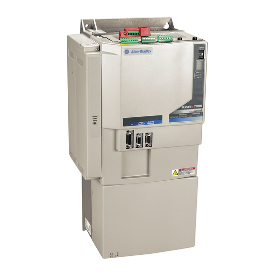
About the Kinetix 7000 Drives
The Kinetix® 7000 high-power servo drives provide a Kinetix Integrated Motion solution for
applications with output power requirements within the range of 22...149 kW (40...248 A rms).
Refer to the Kinetix 7000 High Power Servo Drives User Manual, publication 2099-UM001, for
detailed information on wiring, applying power, troubleshooting, and integration with
ControlLogix®, CompactLogix™, or SoftLogix™ controllers.
Page
1
3
3
4
7
10
17
19
20
Table of Contents

Related Manuals for Allen-Bradley Kinetix 7000


Summary of Contents for Allen-Bradley Kinetix 7000
- Page 1 The Kinetix® 7000 high-power servo drives provide a Kinetix Integrated Motion solution for applications with output power requirements within the range of 22…149 kW (40…248 A rms). Refer to the Kinetix 7000 High Power Servo Drives User Manual, publication 2099-UM001, for detailed information on wiring, applying power, troubleshooting, and integration with...
-
Page 2: Important User Information
2 Kinetix 7000 High Power Servo Drives Important User Information Read this document and the documents listed in the additional resources section about installation, configuration, and operation of this equipment before you install, configure, operate, or maintain this product. Users are required to familiarize themselves with installation and wiring instructions in addition to requirements of all applicable codes, laws, and standards. -
Page 3: Catalog Number Explanation
Kinetix 7000 High Power Servo Drives 3 Catalog Number Explanation This publication applies to the following Kinetix 7000 servo drives. Kinetix 7000 Drive Catalog Numbers Continuous Continuous Output Power Output Current Drive Cat. No. Input Voltage A 0-pk 2099-BM06-S 2099-BM07-S 2099-BM08-S 342…528V AC rms... -
Page 4: Set The Ground Jumper In Select Power Configurations
Set the ground jumper with power removed and the drive mounted on a bench or in a panel. ATTENTION: Kinetix 7000 drives contain protective metal-oxide varistors (MOVs) and common-mode capacitors that are referenced to ground. In a grounded power distribution system, these devices assist in isolating the drive from electromagnetic interference (EMI). -
Page 5: Set The Ground Jumper
Kinetix 7000 High Power Servo Drives 5 Set the Ground Jumper Use the following table and illustrations to set the ground jumpers/wires for ungrounded power. Jumper/Wire Location and Removal Instructions Jumper/ Component Drive Cat. No. Callout No. Description Wire Protected... - Page 6 You must remove the DC-DC converter and drive top cover to access and remove the IMPORTANT common-mode capacitor ground wire. Refer to the Kinetix 7000 DC-DC Converter and Control Board Kits Installation instructions, publication 2099-IN002. Remove the Ground Wires on 2099-BM11-S and 2099-BM12-S Drives The common-mode capacitor ground wire is indicated by callout 5 and the MOV ground wire is indicated by callout 6.
-
Page 7: Install The Kinetix 7000 Drive
SHOCK HAZARD: To avoid hazard of electrical shock, perform all mounting and wiring of the Kinetix 7000 drive prior to applying power. Once power is applied, connector terminals can have voltage present even when not in use. - Page 8 3. Install the recommended mounting bolts listed in the table on page IMPORTANT Each Kinetix 7000 drive requires four mounting bolts. 4. Tighten all mounting fasteners to the value recommended in the table on page Rockwell Automation Publication 2099-IN003C-EN-P - June 2015...
- Page 9 Kinetix 7000 High Power Servo Drives 9 Kinetix 7000 Mounting Dimensions 2099-BM07 Drive Shown 2099-BM06-S 2099-BM11-S Attribute 2099-BM07-S 2099-BM09-S 2099-BM10-S 2099-BM12-S 2099-BM08-S A - Height mm (in.) 517.5 (20.37) 644.5 (25.37) 690.3 (38.47) 977.1 (38.47) B - Width mm (in.) 254.12(10.0)
-
Page 10: Connector Data
10 Kinetix 7000 High Power Servo Drives Connector Data The location of connectors and indicators is identical, regardless of the physical size of the drive. Kinetix 7000 Drive Features and Indicators Kinetix 7000 Drive Module (2099-BM07-S drive, top view is shown) - Page 11 SERCOS fiber-optic (2) ATTENTION: To avoid damage to the SERCOS Rx and Tx connectors, use only finger-tight torque when attaching the fiber-optic cables to a Kinetix 7000 drive. Do not use a wrench or any other mechanical assistance. For more information, refer to Fiber-optic Cable Installation and Handling Instructions, publication 2090-IN010.
-
Page 12: Safe-Off Connector Pinout
12 Kinetix 7000 High Power Servo Drives Safe-off Connector Pinout The Kinetix 7000 drive ships with a (9-pin) wiring-plug header with a motion-allowed jumper installed in the safe-off (SO) connector. With the motion-allowed jumper installed, the safe-off feature is disabled. - Page 13 Kinetix 7000 High Power Servo Drives 13 IOD Connector Pinout IOD Pin Description Signal Hardware enable 24V DC power supply HW_Enable_Pwr Hardware enable input HW_Enable_In Common HW_Enable_Com Home switch 24V DC power supply Home_Switch_Pwr Home switch input Home_Switch_In Common Home_Switch_Com...
- Page 14 (3) Encoder power supply uses either 5V DC or 9V DC based on encoder/motor combination. Combined motor power/feedback cable length must not exceed 90 m (295.2 ft). Additional IMPORTANT limitations apply. Refer to the Kinetix 7000 Multi-axis Servo Drive User Manual, publication 2099-UM001, for more information. IOD, MF, and AF Connector Pin Orientation...
-
Page 15: Input Connector Pinouts
Kinetix 7000 High Power Servo Drives 15 Input Connector Pinouts Control Power (CP) Connector CP Pin Description Signal AUX 24V DC Control power VDC input AUX COM General Purpose I/O (GPIO) Connector GPIO Pin Description Signal Digital output 1 24V DC source for digital output 1 (user-supplied) -
Page 16: Power Terminal Block And Shielding
16 Kinetix 7000 High Power Servo Drives Power Terminal Block and Shielding This section describes the power connections and their location on respective Kinetix 7000 drives. It also shows the recommended power cable shielding for main power. Kinetix 7000 Power Terminal Blocks... -
Page 17: Wiring Requirements
Kinetix 7000 High Power Servo Drives 17 Power Terminal Block (PTB) Connections Terminal Description Name DC+ and DC- Common DC bus for power sharing or external shunting. DC Bus 120V or 230V single-phase AC power input for cooling fan. Applies to catalog 0V AC, 120V AC, numbers 2099-BM09-S, 2099-BM10-S, 2099-BM11-S, and 2099-BM12-S. -
Page 18: Input Power Wiring Requirements
18 Kinetix 7000 High Power Servo Drives Input Power Wiring Requirements Wire Size Torque Value Drive Cat. No. Input Type Signals Terminals (AWG) N•m (lb•in) AC input Ground 2099-BM06 25…2.5 U/Brown 2099-BM07 1.8 (16) (3…14) V/Black 2099-BM08 Motor power W/Blue... -
Page 19: Motor Overload Protection
Kinetix 7000 High Power Servo Drives 19 Motor Overload Protection This servo drive uses solid-state motor overload protection that operates in accordance with UL requirements. Motor overload protection is provided by algorithms (thermal memory) that predict actual motor temperature based on operating conditions as long as control power is continuously applied. -
Page 20: Additional Resources
Rockwell Automation maintains current product environmental information on its website at http://www.rockwellautomation.com/rockwellautomation/about-us/sustainability-ethics/product-environmental-compliance.page. Allen-Bradley, CompactLogix, ControlLogix, Kinetix, Rockwell Software, Rockwell Automation, and SoftLogix are trademarks of Rockwell Automation, Inc. Trademarks not belonging to Rockwell Automation are property of their respective companies.