Table of Contents
Installation Instructions
Original Instructions
Kinetix 3 Component Servo Drives
Catalog Numbers 2071-AP0, 2071-AP1, 2071-AP2, 2071-AP4, 2071-AP8, 2071-A10, 2071-A15
Topic
Summary of Changes
This publication contains new and updated information as indicated in the following table.
Topic
Page
1
2
2
2
5
7
12
13
14
15
17
18
19
Page
4
18
Table of Contents

Related Manuals for Allen-Bradley Kinetix 2071-AP0


Summary of Contents for Allen-Bradley Kinetix 2071-AP0
-
Page 1: Table Of Contents
Installation Instructions Original Instructions Kinetix 3 Component Servo Drives Catalog Numbers 2071-AP0, 2071-AP1, 2071-AP2, 2071-AP4, 2071-AP8, 2071-A10, 2071-A15 Topic Page Summary of Changes Catalog Number Explanation Before You Begin Safety Information Product Dimensions Connector Data Power Wiring Requirements Connectors and Cables Ground Your Kinetix 3 Drive to the Subpanel Kinetix 3 Drive Power and Ground Wiring Motor Overload Protection... -
Page 2: Catalog Number Explanation
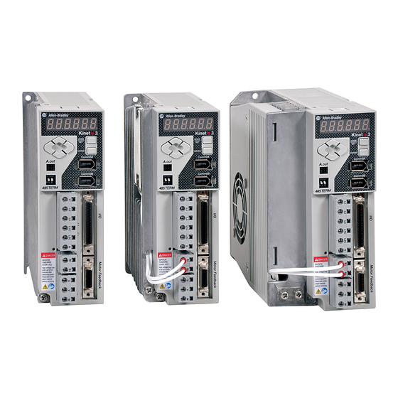
Kinetix 3 Component Servo Drives About the Kinetix 3 Drives Kinetix® 3 component servo drives provide simple solutions for applications with output power requirements in the range of 50…1500 W (0.6…9.9 A rms). See the Kinetix 3 Component Drive User Manual, publication 2071-UM001, for detailed information on how to wire, apply power, troubleshoot, and integrate with Micro800®... - Page 3 Kinetix 3 Component Servo Drives WARNING: The opening of branch-circuit protective device can be an indication that a fault has been interrupted. To reduce the risk of fire or electric shock, parts that carry current and other components of the controller must be examined and replaced if damaged. Parts List The Kinetix 3 drive ships with the following: •...
-
Page 4: Added An Important Statement To Step 2 Of The Mount The Kinetix 3 Drive Procedure
Kinetix 3 Component Servo Drives Mount the Kinetix 3 Drive Follow these steps to mount the drive. 1. Observe these clearance requirements when mounting the drive to the panel. Dimensions are in millimeters (inches) 50.0 (1.97) Minimum Panel Depth 30.0 (1.18) 10.0 (0.39) 235 (9.25) 50.0 (1.97) -
Page 5: Product Dimensions
Kinetix 3 Component Servo Drives Product Dimensions Catalog Numbers 2071-AP0, 2071-AP1, and 2071-AP2 153.4 53.0 (6.04) (2.09) 141.0 48.3 50.0 (5.55) (0.2) (1.9) (1.97) 155.0 145.0 (6.11) (5.71) Mounting hole (top) and slot Chassis Ground (bottom) require M4 x 10 bolts. (0.2) Dimensions are in millimeters (inches). - Page 6 Kinetix 3 Component Servo Drives Catalog Numbers 2071-AP8, 2071-A10, and 2071-A15 81.0 198.6 (3.19) (7.82) 50.0 59.0 186.2 (0.2) (1.97) (2.32) (7.34) 145.0 155.0 (5.71) (6.11) Mounting hole (top) and slot Chassis Ground (bottom) require M5 x 10 bolts. Terminals (2) Dimensions are in millimeters (inches).
-
Page 7: Connector Data
Kinetix 3 Component Servo Drives Connector Data Use this illustration to identify the Kinetix 3 drive features and indicators. Kinetix 3 Features and Indicators Item Description Left/right and up/down keys Analog output (A.out) RS-485 communication termination switch Input power (IPD) Main power indicator Shunt power (BC) Motor power (MP) - Page 8 Kinetix 3 Component Servo Drives Input Power (IPD) Connector IPD Pin Description Signal Main AC power Main AC power Main AC power L1C - Control power L2C - Control power DC bus negative DC- (not supported) (1) L3 is not used for single phase drives. Shunt Power (BC) Connector BC Pin Description...
- Page 9 Kinetix 3 Component Servo Drives Motor Feedback (MF) Connector MF Pin Description Signal Shield drain Reserved – Serial negative Hall feedback S2 Reserved – Hall feedback S3 Positive limit sensor input LMT+ BAT+ for motor side BAT+ BAT- for motor side BAT- Encoder +5 input power EPWR...
- Page 10 Kinetix 3 Component Servo Drives I/O (IOD) Connector (continued) IOD Pin Description Signal E-stop (default: disable) ESTOP Follower input A+ PLUS + Follower input A- PLUS - Follower input B+ SIGN + Follower input B- SIGN - High frequency pulse input A+ HF_PULS + High frequency pulse input A- HF_PULS -...
- Page 11 Kinetix 3 Component Servo Drives I/O (IOD) Connector (continued) IOD Pin Description Signal Alarm output FCOM Digital outputs ground OUT COM Digital output 1 + (P_COM+) OUTPUT1+ Digital output 1 – (P_COM-) OUTPUT1- Digital output 2 + (TG_ON+) OUTPUT2+ Digital output 2 – (TG_ON-) OUTPUT2- Servo alarm + FAULT+...
-
Page 12: Power Wiring Requirements
Kinetix 3 Component Servo Drives Power Wiring Requirements The wires must be copper with 75 °C (167 °F) minimum rating. The phase connections of the main AC power are arbitrary and earth ground connection is required for safe and proper operation. -
Page 13: Connectors And Cables
Kinetix 3 Component Servo Drives Connectors and Cables Connector Type of Connector Wire Size Cat. No. Input Power 2.5…0.08 mm Single-row, spring clamp (12…28 AWG) connectors spaced 7.5 mm 2071-CONN1 8 mm (0.31 in.) of wire Output (Motor) Power (0.30 in.) that is exposed Input/output 50-pin mini-D... -
Page 14: Ground Your Kinetix 3 Drive To The Subpanel
Kinetix 3 Component Servo Drives Ground Your Kinetix 3 Drive to the Subpanel Bond the Kinetix 3 drive to the cabinet ground bus. To ground, attach a braided ground strap or 0.4 mm (12 AWG) solid-copper wire, 100 mm (3.9 in.) long between the top mounting screw and the bonded cabinet ground. -
Page 15: Kinetix 3 Drive Power And Ground Wiring
Kinetix 3 Component Servo Drives Kinetix 3 Drive Power and Ground Wiring This installation applies to a TL-Series™ (Bulletin TL) motor with 2090-DANPT-16S cable. Terminate the input-power ground wire with a ring lug. Attach input power and motor power grounds to ground screws, and torque to 1.25 N•m (11 lb•in). Item Description 2071-AP4 Kinetix 3 drive shown... - Page 16 Kinetix 3 Component Servo Drives This installation applies to TL-Series™ (Bulletin TLY) rotary motors, LDC-Series™ and LDL- Series™ linear motors, and MP-Series™ (Bulletin MPAS), TL-Series (Bulletin TLAR), and LDAT-Series actuators. Terminate the input-power ground wire with a ring lug as shown. Attach input power and motor power grounds to ground screws, and torque to 1.25 N•m (11 lb•in).
-
Page 17: Motor Overload Protection
Kinetix 3 Component Servo Drives Motor Overload Protection This servo drive uses solid-state motor overload protection that operates in accordance with UL 508C. Motor overload protection algorithms (thermal memory) that predict actual motor temperature that is based on operating conditions as long as control power is continuously applied. -
Page 18: Fuse/Contactor Specifications
Kinetix 3 Component Servo Drives Fuse/Contactor Specifications The Kinetix 3 drives use internal solid-state motor short-circuit protection and, when protected by suitable branch circuit protection, are rated for use on a circuit capable of delivering up to 100,000 A. Fuses or circuit breakers, with adequate withstand and interrupt ratings, as defined in NEC or applicable local codes, are permitted. -
Page 19: Additional Resources
Provides declarations of conformity, certificates, and other http://www.rockwellautomation.com/global/ certification details. certification/overview.page You can view or download publications at http://www.rockwellautomation.com/global/ literature-library/overview.page. To order paper copies of technical documentation, contact your local Allen-Bradley distributor or Rockwell Automation sales representative. Rockwell Automation Publication 2071-IN001F-EN-P - February 2017... - Page 20 Rockwell Automation maintains current product environmental information on its website at http://www.rockwellautomation.com/rockwellautomation/about-us/sustainability-ethics/product-environmental-compliance.page. Allen-Bradley, Kinetix, LDC-Series, LDL-Series, Micro810, Micro830, Micro850, MicroLogix, MP-Series, Rockwell Automation, Rockwell Software, and TL-Series are trademarks of Rockwell Automation, Inc. Trademarks not belonging to Rockwell Automation are property of their respective companies.