Allen-Bradley Kinetix 5700 Installation Instructions Manual
Dc-bus power supply
2198-p031;2198-p070;
2198-p141;2198-p208
Hide thumbs
Also See for Kinetix 5700:
- User manual (460 pages) ,
- Reference manual (126 pages) ,
- Installation instructions manual (16 pages)
Table of Contents
Quick Links
Installation Instructions
Kinetix 5700 DC-bus Power Supply
Catalog Numbers 2198-P031, 2198-P070, 2198-P141, 2198-P208
Topic
About the DC-bus Power Supply
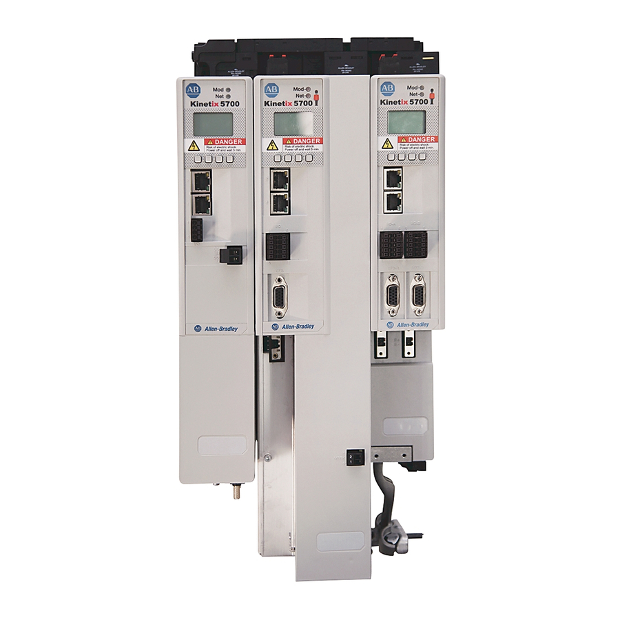
The Kinetix® 5700 DC-bus (converter) power supply with 400V-class three-phase AC input
provides continuous output power and current to servo drives for applications with requirements
in the range of 7...46 kW and 10.5...69.2 A, respectively.
See the Kinetix 5700 Servo Drives User Manual, publication 2198-UM002, for detailed
information on wiring, applying power, troubleshooting, and integration with ControlLogix®
EtherNet/IP communication modules or CompactLogix™ 5370 controllers.
Page
1
2
3
3
3
5
6
9
12
14
15
15
Table of Contents

Related Manuals for Allen-Bradley Kinetix 5700


Summary of Contents for Allen-Bradley Kinetix 5700
-
Page 1: Table Of Contents
7…46 kW and 10.5…69.2 A, respectively. See the Kinetix 5700 Servo Drives User Manual, publication 2198-UM002, for detailed information on wiring, applying power, troubleshooting, and integration with ControlLogix®... -
Page 2: Important User Information
2 Kinetix 5700 DC-bus Power Supplies Important User Information Read this document and the documents listed in the additional resources section about installation, configuration, and operation of this equipment before you install, configure, operate, or maintain this product. Users are required to familiarize themselves with installation and wiring instructions in addition to requirements of all applicable codes, laws, and standards. -
Page 3: Catalog Number Explanation
Kinetix 5700 DC-bus Power Supplies 3 Catalog Number Explanation This publication applies to the following Kinetix 5700 DC-bus power supplies. DC-bus Power Supply Catalog Numbers Module Continuous Continuous DC-bus Power Supply Width Output Power Output Current Input Voltage Cat. No. - Page 4 4 Kinetix 5700 DC-bus Power Supplies We recommend that you remove the grounding screw when the drive module is removed from the panel and placed on its side on a solid surface equipped as a grounded static-safe workstation. ATTENTION: When you remove the grounding screw, the risk of equipment damage exists because the unit no longer maintains line-to-neutral voltage protection.
-
Page 5: Install The Dc-Bus Power Supply
• Impedance grounded • Reduced leakage current (1) Refer to the Kinetix 5700 Servo Drives User Manual, publication 2198-UM002, for example configurations. Install the DC-bus Power Supply These procedures assume that you have prepared your panel and understand how to bond your system. -
Page 6: Drilling Hole Patterns
Mount the drive module in an upright position as shown. Do not mount the drive module on IMPORTANT its side. The Kinetix 5700 drive system must be spaced by aligning the zero-stack tab and cutout. For mounting, sizing, and configuring shared-bus configurations, refer to the Kinetix 5700 Servo Drives User Manual, publication 2198-UM002. - Page 7 420 (16.54) Lower Mounting Hole Applies to only 2198-S160-ERS3 Single-axis Inverter 465 (18.31) Lower Mounting Hole Also available to assist you with mounting holes is the Kinetix 5700 System Mounting Toolkit, catalog number 2198-K5700-MOUNTKIT. Rockwell Automation Publication 2198-IN009B-EN-P - June 2015...
-
Page 8: Product Dimensions
8 Kinetix 5700 DC-bus Power Supplies Product Dimensions Refer to the Kinetix Servo Drives Technical Data, publication GMC-RM003, for product dimensions of all Kinetix 5700 drive modules. Dimensions are in mm (in.) 12.0 (0.47) 2198-P031 DC-bus Power Supply is Shown DC-bus Power Supply Cat. -
Page 9: Connector Data
Kinetix 5700 DC-bus Power Supplies 9 Connector Data Use this illustration to identify the DC-bus power supply features and indicators. DC-bus Power Supply Features and Indicators (2198-P031 power supply is shown) MOD– NET– 5700 DC– 24V– 24V+ DC-bus Power Supply... - Page 10 The contactor-enable circuitry includes a relay-driven contact within the 2198-P DC-bus power supply. The relay protects the Kinetix 5700 drive system in the event of overloads or other fault conditions. An AC three-phase mains contactor must be wired in series between the branch circuit protection and the DC-bus power supply.
- Page 11 Kinetix 5700 DC-bus Power Supplies 11 ATTENTION: Wiring the contactor-enable relay is required. To avoid personal injury or damage to the Kinetix 5700 drive system, wire the contactor-enable relay into your control string so that: • three-phase power is removed and the DC-bus power supply is protected under various fault conditions.
-
Page 12: Wiring Requirements
12 Kinetix 5700 DC-bus Power Supplies Wiring Requirements Wire must be copper with 75 C (167 F) minimum rating. Phasing of mains AC power is arbitrary and earth ground connection is required for safe and proper operation. The National Electrical Code and local electrical codes take precedence over the values and IMPORTANT methods provided. - Page 13 Kinetix 5700 DC-bus Power Supplies 13 Ground Your DC-bus Power Supply to the Subpanel Ground Kinetix 5700 drives and Bulletin 2198 capacitor modules to a bonded-cabinet ground bus with a braided ground strap. Keep the braided ground strap as short as possible for optimum bonding.
-
Page 14: Circuit Breaker/Fuse Specifications
14 Kinetix 5700 DC-bus Power Supplies Rockwell Automation Publication 2198-IN009B-EN-P - June 2015... -
Page 15: Specifications
• current Kinetix 5700 drives produce DC current in the protective-earthing conductor and can reduce the ability of a residual current device (RCD) or residual current monitor (RCM) of type A or AC to provide protection for the drive module and other equipment in the installation. -
Page 16: Installation Assistance
Rockwell Automation Support Rockwell Automation provides technical information on the Web to assist you in using its products. http://www.rockwellautomation.com/support you can find technical and application notes, sample code, and links to software service packs. You can also visit our Support Center at https://rockwellautomation.custhelp.com/ for software updates, support chats and forums, technical information, FAQs, and to sign up for product notification updates.