Emerson 1410 Quick Start Manual
Emerson smart wireless gateway 1410
Hide thumbs
Also See for 1410:
- Reference manual (76 pages) ,
- Reference manual (66 pages) ,
- Reference manual (68 pages)

Related Manuals for Emerson 1410


Summary of Contents for Emerson 1410
- Page 1 Quick Start Guide 00825-0200-4410, Rev CA October 2014 Emerson Smart Wireless Gateway 1410...
-
Page 2: Table Of Contents
00809-0200-4410) for more information and instructions. The manual and this guide are available electronically on www.emersonprocess.com. Explosion Hazard - Do not make or break any connections to the 1410 while circuits are live unless area is known to be non-hazardous. Explosions could result in death or serious injury: Installation of this device in an explosive environment must be in accordance with the appropriate local, national, and international standards, codes, and practices. -
Page 3: Wireless Considerations
Wireless Considerations Power up sequence The Emerson Smart Wireless Gateway 1410 (Gateway) should be installed and functioning properly before Power Modules are installed in any wireless field devices. Wireless field devices should also be powered up in order of proximity from the Gateway beginning with the closest. -
Page 4: Initial Connection And Configuration
Step 1: Initial connection and configuration To configure the Emerson Smart Wireless Gateway 1410, a local connection between a PC/Laptop and the Gateway needs to be established. The 1410 and the 1410D are operationally equivalent and the following instructions are applicable to both models. -
Page 5: Establishing A Connection
Quick Start Guide October 2014 Figure 2. 1410D Wiring Diagram A. 1410 Power and Serial Connections B. Smart Wireless Field Link Power and Data Connections Establishing a connection 1. Connect the PC/Laptop to the Ethernet 1 (Primary) receptacle on the Gateway using an Ethernet cable. - Page 6 October 2014 Quick Start Guide b. Right click to select Properties. c. Select Internet Protocol (TCP/IP), then select the Properties button. Note If the PC/laptop is from another network, record the current IP address and other settings so the PC/laptop can be returned to the original network after the Gateway has been configured. d.
- Page 7 Quick Start Guide October 2014 Configure the Emerson Smart Wireless Gateway 1410 To complete initial configuration for the gateway: 1. Access the default web page for the Gateway at https://192.168.1.10. a. Log on as User: admin b. Type in password: default...
- Page 8 October 2014 Quick Start Guide 2. Navigate to Setup>Ethernet Protocol>Address to enter the Network Settings. a. Configure a static IP Address or set for DHCP and enter a Hostname Table 2. Network Settings Gateway PC/laptop Subnet Ethernet 1 192.168.1.10 192.168.1.12 255.255.255.0 Ethernet 2 192.168.2.10...
-
Page 9: Physical Installation
The remote antenna options provide flexibility for mounting the Gateway based on wireless connectivity, lightning protection, and current work practices. When installing remote mount antennas for the Emerson 1410 Smart Wireless Gateway, always use established safety procedures to avoid falling or contact with high-power electrical lines. - Page 10 October 2014 Quick Start Guide Figure 3. Installation of WL2/WN2 Option Note: Weather proofing is required The remote mount antenna kit includes coaxial sealant for the cable connections for the lightning arrestor, antenna, and Gateway. The coaxial sealant must be applied to guarantee performance of the wireless field network.
- Page 11 1. Wire the Gateway’s Ethernet 1 (Primary) or Serial Output connection to the Host System Network or Serial I/O. 2. For Serial connections, connect A to A, B to B, making sure all terminations are clean and secured to avoid wiring connection problems. Figure 5. 1410 Wiring Diagram Power Reset 24 VDC...
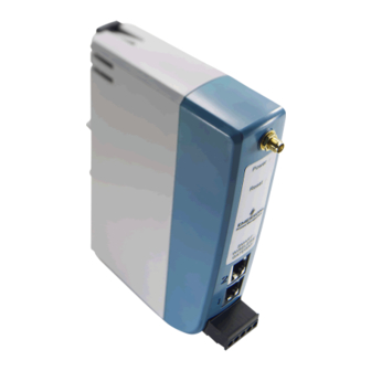
- Page 12 October 2014 Quick Start Guide Figure 6. 1410D Housing Diagram A. DIN Rail clip B. Power and Reset indicator lights. During normal operation the power indicator will be green. During a reset the reset light will turn red. The reset switch should not be enabled during normal operation.
-
Page 13: Software Installation (Optional)
If the autorun function is disabled on the PC, or installation does not begin automatically, double click D:\SETUP.EXE (where D is the CD/DVD drive on the PC) and select OK. For more information about the Security Setup Utility and AMS Wireless Configurator, see the Emerson Smart Wireless Gateway 1410 Reference Manual (document number 00809-0200-4410). Note For information on how to connect with a Windows 7 PC, please see the Gateway overview supplement (document number 00840-0900-4420). -
Page 14: Verify Operations
Explore tab using the web interface. The time needed for the network to form will depend on the number of devices. For more detailed installation instructions, see the Emerson Smart Wireless Gateway 1410 Reference Manual (document number 00809-0200-4410). -
Page 15: Product Certification
60 °C) Special Condition for Safe Use (X): 1. When installed as Division 2 equipment, the 1410 shall be mounted within a tool-secured enclosure which meets the requirements of ANSI/ISA 61010-1 and be capable of accepting the applicable wiring methods per the NEC. - Page 16 October 2014 Quick Start Guide CSA Class I Division 2 Certificate: 2646342 Standards Used: CSA Std. C22.2 No. 0-10, CSA Std. C22.2 No. 213 - M1987, CSA Std. C22.2 No.61010-1-12, ANSI/ISA 12.12.01-2012, ANSI/ISA 61010-1-2012 Markings: SUITABLE FOR CL I, DIV. 2, GP A, B, C, D ≤...
-
Page 17: Declaration Of Conformity
Quick Start Guide October 2014 Declaration of Conformity... - Page 18 October 2014 Quick Start Guide...
- Page 19 Quick Start Guide October 2014...
- Page 20 © 2014 Rosemount Inc. All rights reserved. All marks property of owner. Instrument Co., Limited The Emerson logo is a trade mark and service mark of Emerson Electric Co. No. 6 North Street, Hepingli, AMS, Rosemount, and the Rosemount logotype are registered trademarks of Dong Cheng District Rosemount Inc.