
Related Manuals for Emerson 1410H


Summary of Contents for Emerson 1410H
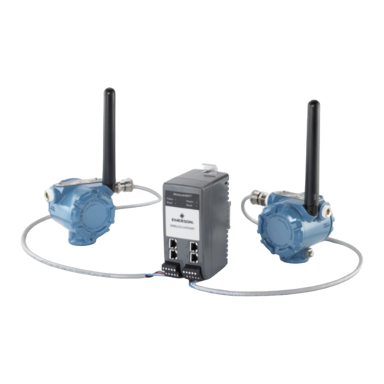
- Page 1 Reference Manual 00809-0500-4410, Rev AA February 2019 ™ Emerson Wireless 1410H Gateway and 781 Field Links...
- Page 2 Verify that the operating environment of the transmitter is consistent with the appropriate hazardous locations certifications. • Do not make or break connections to the Emerson 1410H while circuits are live unless the area is known to be non-hazardous. •...
-
Page 3: Table Of Contents
Installation........................19 Safety messages............................19 3.2 Installation overview........................20 3.3 Installing the Gateway........................20 3.4 Installing the 781 Field Links......................21 3.5 Connecting the Emerson 1410H with 781 Field Links..............23 3.6 Verify operations..........................28 3.7 RS-485............................28 3.8 Terminating resistors........................29 Chapter 4 Commissioning......................31 4.1 Overview............................ - Page 4 Chapter 7 Appendix A........................47 7.1 Product Certifications........................47 7.2 Ordering Information, Specifications, and Dimensional Drawings..........47 Chapter 8 Appendix B........................49 8.1 Emerson 1410H Product Certifications................... 49 8.2 Emerson 781 Product Certifications....................51 Chapter 9 Appendix C........................55 9.1 Overview............................55 9.2 Requirements..........................55 9.3 Setup .............................
-
Page 5: Chapter 1 Introduction
Wireless 1410H Gateway and 781 Field Links ™ ® The Emerson Wireless 1410H Gateway and 781 Field Links provides two WirelessHART ® networks to allow for redundancy or to add more field devices. Modbus communications over RS-485 or Ethernet provide universal integration and system interoperability. The ™... - Page 6 Introduction Reference Manual February 2019 00809-0500-4410 Emerson.com/Rosemount...
-
Page 7: Chapter 2 Configuration
Verify that the operating environment of the transmitter is consistent with the appropriate hazardous locations certifications. • Do not make or break connections to the Emerson 1410H while circuits are live unless the area is known to be non-hazardous. •... -
Page 8: Wireless Planning
Initial connection To configure the Gateway, a local connection between a PC/MAC/laptop and the Gateway ® ™ needs to be established. The WirelessHART networks in the Emerson 1410H Gateway are operationally equivalent and the following instructions are applicable to both. Emerson.com/Rosemount... -
Page 9: Establishing A Connection
D. Ethernet port 1. When this port is activated the factory IP address is 192.168.1.10. E. Emerson 1410H Power and Serial connections. Black terminal included in the box. F. Emerson Wireless 781 Field Link power and data connections. Black terminal included in the box. Establishing a connection Connect the PC/laptop to the Ethernet 1 (Primary) receptacle on the Gateway using an Ethernet cable. - Page 10 Reference Manual February 2019 00809-0500-4410 Figure 2-2: Internet Access 2. Select the Network and Sharing Center. 3. Select Local Area Connection. Figure 2-3: Local Area Connection 4. Select Properties. 5. Select Internet Protocol Version 4 (TCP/IPv4) then select Properties. Emerson.com/Rosemount...
- Page 11 Figure 2-5: IP Address 7. In the IP address field, enter 192.168.1.12 (DeltaV Ready enter 10.5.255.12). 8. In the Subnet mask field, enter 255.255.255.0. 9. Select OK for both the Internet Protocol (TCP/IP) Properties window and the Local Area Connection Properties window. Emerson.com/Rosemount...
-
Page 12: Disable Proxies
Use these steps to complete the initial configuration for the Gateway. This will need to be done for both the WirelessHART and ISA100 networks. Procedure 1. Access the WirelessHART default web page for the Gateway at https:// 192.168.1.10. You will have to configure both networks individually. Emerson.com/Rosemount... - Page 13 Configure a static IP Address or set for DHCP and enter a Hostname. Figure 2-9: Ethernet Communication b) If not prompted, restart application at System Settings > Gateway > Backup and Restore > Restart Apps. Note Resetting applications will temporarily disable communications with field devices. Emerson.com/Rosemount...
-
Page 14: User Accounts
Procedure 1. Navigate to System Settings > Users > User Accounts. 2. Click on the Edit button of the user password to be changed. 3. Set the new password for the role based account, and confirm. Emerson.com/Rosemount... -
Page 15: Time Settings
3. Manual Entry. This option allows the user to enter a specific date (MM:DD:YY) and time (HH:MM:SS). Note Network Time Protocol (NTP) is recommended for the best network performance because it always adjusts time to match the network time server. Emerson.com/Rosemount... -
Page 16: Tcp/Ip Network Settings
2. Select Specify an IP address (recommended). 3. Enter the following: • Hostname • Domain Name • IP Address • Netmask • Gateway 4. Select Save Changes. 5. When prompted, select Restart Apps. 6. Select Yes to confirm restart. 7. Close the web browser. Emerson.com/Rosemount... -
Page 17: System Backup
Note Following this procedure will cause the network to reform and all configuration parameters will be reset to factory defaults. Once the Gateway is reset, the user is strongly recommended to change the default password to maintain system security. Emerson.com/Rosemount... -
Page 18: Disconnect The Power
Gateway will now be programmed back to factory defaults including IP addresses. The factory default IP addresses can be found in the table in the Initial connection section of Troubleshooting. 2.16 Disconnect the power Disconnect the power and Ethernet cables from the Gateway. Emerson.com/Rosemount... -
Page 19: Chapter 3 Installation
Verify that the operating environment of the transmitter is consistent with the appropriate hazardous locations certifications. • Do not make or break connections to the Emerson 1410H while circuits are live unless the area is known to be non-hazardous. •... -
Page 20: Installation Overview
Using an uninterruptible power supply (UPS) is recommended to ensure availability during power failure. 3.3.2 Mounting the Gateway The unit can be snapped onto a DIN TS35/7.5 or TS35/15 rail system. Procedure 1. Push the DIN rail lever downwards so the spring compresses, and hold. Emerson.com/Rosemount... -
Page 21: Installing The 781 Field Links
The Field Link must be used in conjunction with a network manager or network Gateway. The Field Link then functions as a translator between the wired network and a wireless field network. Figure 3-2 shows one of the networks being used. Figure 3-2: System Architecture Example Emerson.com/Rosemount... - Page 22 7,6 m) above the ground or 6 ft. (2 m) above obstructions or major infrastructure. The two 781s do not need to be installed near each other, unless the Emerson 1410H is being used for redundancy (Appendix D). There should be at least 3 ft. (1m) between the two.
-
Page 23: Connecting The Emerson 1410H With 781 Field Links
Upon installation, ensure each conduit entry is either sealed with a conduit plug using approved thread sealant, or has an installed conduit fitting or cable gland with appropriate threaded sealant. Note the conduit entries on the Emerson 781 Field Link are threaded ½– 14 NPT. - Page 24 A shielded twisted-pair cable is needed for connecting the Emerson 1410H and 781 Field Links. Each Emerson 781 can be located up to 656 ft. (200m) from the Emerson 1410H. This will need to be done twice for the two networks.
- Page 25 Installation 00809-0500-4410 February 2019 The signal barrier needs additional power. You can wire it to the Emerson 1410H terminals or to a separate power supply. Make sure power supply is rated to handle power drawn for the barrier. Figure 3-7...
- Page 26 Installation Reference Manual February 2019 00809-0500-4410 Figure 3-8: Emerson 1410H and 781 with Additional Power Supplied Barrier Installation A. Emerson Wireless 1410H Gateway B. Attach shield pair cable (Belden 3083A) C. Tape back shield wire and foils D. Short these terminals for 250Ω...
- Page 27 Shield grounding The shields of the twisted-pair cables need to be grounded using the grounding terminal on the Emerson 1410H, and it should be taped back on the Emerson 781 side. Figure 3-9: Emerson 1410H Grounding A. #6 AWG copper wire B.
-
Page 28: Verify Operations
A and the Rx + (positive, transmit) wire to terminal B. The wiring shield should be trimmed close and insulated from touching the Gateway enclosure or other terminations. If the existing data bus uses a 4-wire Full Duplex configuration, see Figure 3-11 to convert to a 2-wire Half Duplex configuration. Emerson.com/Rosemount... -
Page 29: Terminating Resistors
Three DIP switches are provided to enable various terminating resistors to the RS-485 data bus. The switches are found inside the electronics housing, located behind an access slot on the upper right side. The switches number bottom to top 1 through 3 and the upward position is ON. Emerson.com/Rosemount... - Page 30 Installation Reference Manual February 2019 00809-0500-4410 Emerson.com/Rosemount...
-
Page 31: Chapter 4 Commissioning
Overview This section discusses the installation and setup of the optional software included with the ™ Emerson Smart Wireless Gateway. The following table describes what items are installed and on which disk they can be found. Table 4-1: Software Applications... -
Page 32: Software Installation
Security Setup Utility. These proxies can function as a data server for other applications on the control network. The Security Setup Utility can support multiple Gateways at once and each proxy can support multiple client application connects. Figure 4-1 shows a typical system architecture using the Security Setup Utility. Emerson.com/Rosemount... -
Page 33: Ams Wireless Configurator
Provision a wireless device using the drag-and-drop operation so it can join a Gateway’s self-organizing network • Enhance AMS Wireless Configurator functionality with the AMS Wireless SNAP-ON Application • Restrict access to AMS Wireless Configurator functions through the use of security permissions Emerson.com/Rosemount... -
Page 34: Licensing And Credits
Configurator. To display the release notes, navigate to Start>Programs>AMS Wireless Configurator>Help. Licensing and credits The latest licensing agreements are included on each disk of the software pack. This product includes software developed by the OpenSSL Project for use in the OpenSSL Toolkit. Emerson.com/Rosemount... -
Page 35: Operation And Maintenance
Figure 5-1) using a network switch, router, or hub. Often there are two networks for redundancy purposes. Figure 5-1: Ethernet Architecture A. Engineering station B. Primary control network C. Secondary control network D. Controller and I/O E. Wireless Gateway Emerson.com/Rosemount... -
Page 36: Modbus
Modbus The Gateway supports both Modbus RTU over the RS-485 serial port and Modbus TCP over Ethernet. It functions as a sub device on the Modbus network and must be polled by a Modbus master or client (host system). Emerson.com/Rosemount... - Page 37 Baud Rate: The data rate or speed of serial communications. This setting is only required for Modbus RTU. Parity: This setting determines parity (none, even, or odd) used for error checking purposes. This setting is only required for Modbus RTU. Emerson.com/Rosemount...
- Page 38 Global scale gain: This value is multiplied by the data values for the purpose of scaling integers. If global scaling is not selected, a gain value will be available for each separate data value on the Modbus Mapping page. Emerson.com/Rosemount...
- Page 39 Global scale offset: This value is added to the data values for the purpose of scaling integers. If global scaling is not selected, an offset value will be available for each separate data value on the Modbus Mapping page. Emerson.com/Rosemount...
- Page 40 Operation and Maintenance Reference Manual February 2019 00809-0500-4410 Emerson.com/Rosemount...
-
Page 41: Chapter 6 Troubleshooting
February 2019 Troubleshooting Service support To expedite the return process outside of the United States, contact the nearest Emerson representative. Within the United States, call the Emerson Instrument and Valve Response Center using the 1-800-654-RSMT (7768) toll-free number. This center, available 24 hours a day, will assist you with any needed information or materials. -
Page 42: Initial Connection
155.177.0.yyy). Verify this option was ordered with the Gateway. Cannot log into the Gateway • Verify the user name and password. The administrator user name is admin and the default password is default. • If unable to connect, consider resetting the Gateway. Emerson.com/Rosemount... -
Page 43: Ams Wireless Configurator
• Re-enter the Network ID and Join Key into the device. Wireless device appears with service denied • Verify the total number of devices on the network (100 max per network). • Reduce the update rate for the device. Emerson.com/Rosemount... -
Page 44: Modbus Communications
Gateway. Log on to the Gateway and navigate to SYSTEM SETTINGS > PROTOCOLS > MODBUS. • Verify Modbus register mapping in the Gateway. Log on to the Gateway and navigate to SYSTEM SETTINGS > PROTOCOLS > MODBUS. Emerson.com/Rosemount... -
Page 45: Opc Communications
To expedite the return process outside of North America, contact your Emerson representative. Within the United States, call the Emerson Response Center toll-free number 1 800 654 7768. The center, which is available 24 hours a day, will assist you with any needed information or materials. - Page 46 Troubleshooting Reference Manual February 2019 00809-0500-4410 Emerson.com/Rosemount...
-
Page 47: Chapter 7
3. Click Manuals & Guides. 4. Select the appropriate Quick Start Guide. Ordering Information, Specifications, and Dimensional Drawings To view current Rosemount 1410H Ordering Information, Specifications, and Dimensional Drawings, follow these steps: Procedure 1. Go to Emerson.com/Rosemount/1410H. 2. Scroll as needed to the green menu bar and click Documents & Drawings. - Page 48 Appendix A Reference Manual February 2019 00809-0500-4410 Emerson.com/Rosemount...
-
Page 49: Chapter 8
Appendix B 00809-0500-4410 February 2019 Appendix B Emerson 1410H Product Certifications Rev. 2.0 European Directive Information A copy of the EC Declaration of Conformity can be found at the end of the Quick Start Guide. The most recent revision of the EC Declaration of Conformity can be found at Emerson.com/Rosemount. - Page 50 Equipment must be installed in a suitable tool accessible enclosure subject to the end use application. • Using the 1410H and the 781 Field Links in a hazardous location requires barriers between the two units. Europe N1 ATEX Type n...
-
Page 51: Emerson 781 Product Certifications
4. When fitted, the surface resistivity of the remote antenna is greater than 1GΩ. To avoid electrostatic charge build-up, it must not be rubbed with a dry cloth or cleaned with solvents. • Currently not available for 1410H option. Emerson 781 Product Certifications Rev. 1.1 European Directive Information A copy of the EC Declaration of Conformity can be found at the end of the Quick Start Guide. - Page 52 60079-11. This must be taken into account when installing the apparatus. International I7 IECEx Intrinsic Safety Certificate IECEx BAS 11.0028X Standards IEC 60079-0: 2011, IEC 60079-0: 2007-10, IEC 60079-11: 2011 Ex ia IIC T4 Ga (-40 °C ≤ Ta ≤ +70 °C) Markings Emerson.com/Rosemount...
- Page 53 0Ex ia IIC T4 Ga X -40ºC ≤ Ta ≤ 70ºC Input parameters Input parameters Output (power terminals) (RS485) parameters (RS485) = 30B = 11B = 7.14B = 200 = 300 = 112 = 1B = 1B = 1B = 5.1 = 13.9 Emerson.com/Rosemount...
- Page 54 I2 INMETRO Intrinsic Safety Certificate UL-BR 16.0478X Standards ABNT NBR IEC 60079-0:2013 ABNT NBR IEC 60079-11:2013 Markings Ex ia IIC T4 Ga, -40 + 70 °C IP66, UL BR Special Conditions for Safe Use (X): 1. See certificate for special conditions. Emerson.com/Rosemount...
-
Page 55: Chapter 9
Overview ™ Redundancy for the Emerson Wireless 1410H Gateway (Gateway) increases the availability of the wireless field network by providing two sets of physical hardware which operate as a single Gateway system. This section covers setup and installation of a redundant Gateway system. - Page 56 4. Connect the secondary Ethernet port on Gateway A to the secondary Ethernet port on Gateway B (see Figure 9-2, Redundancy Setup Connections). 5. After a few minutes, a dialog will appear on the page; select Form redundant pair. 6. Wait for the Pairing to redundant peer status to turn green. Emerson.com/Rosemount...
- Page 57 Reference Manual Appendix C 00809-0500-4410 February 2019 Figure 9-2: Redundancy Setup Connections A. Gateway A B. Gateway B C. PC/Laptop D. Primary Ethernet E. Secondary Ethernet Figure 9-3: Redundant Pair Emerson.com/Rosemount...
- Page 58 Gateway on the left hand side and Gateway B will be the standby Gateway on the right. If significant configuration changes need to be downloaded to the standby Gateway, it may temporarily go offline shortly after the pair process is complete. This is expected behavior and does not represent instability in the system. Emerson.com/Rosemount...
-
Page 59: Mounting And Connections
The two Emerson 781 Field Links should be mounted at the same height and be spaced between 3–9 ft. (1–3 m) horizontally. This is to ensure that they provide identical coverage for the wireless field network and to help eliminate coverage gap in the event of a switch over. - Page 60 Ethernet port on Gateway A directly to the secondary Ethernet port on Gateway B. Then wire the RS-485 ports for both Gateways in parallel to a single serial card at the host system. See Figure D-5, Simplex RS-485 Architecture. Emerson.com/Rosemount...
- Page 61 Ethernet port on Gateway A directly to the secondary Ethernet port on Gateway B. Then wire the RS-485 ports for both Gateways separately to dual serial cards at the host system. See Figure D-6, Dual RS-485 Architecture. Emerson.com/Rosemount...
-
Page 62: Diagnostics
These diagnostics can also be mapped to Modbus registers or OPC tags. The following table covers what diagnostics are included on the Redundancy Status page as well as how they can be mapped as parameters in Modbus or OPC. Emerson.com/Rosemount... - Page 63 Gateway should be set to the active Gateway. To configure network connectivity check: 1. Navigate to System Settings>Gateway>Ethernet Communication. 2. Enter the host system IP address in the Check Network Connectivity IP Address field. 3. Select Save Changes. Emerson.com/Rosemount...
-
Page 64: Gateway Replacement
If the Gateway is new or has been set to default configuration, it will need to be paired to the current active Gateway. Navigate to System Settings>Gateway>Redundancy and follow the recommended actions on that page or follow the procedure above to pair Gateways and form a redundant system. Emerson.com/Rosemount... - Page 65 Reference Manual 00809-0500-4410 February 2019 Emerson.com/Rosemount...
- Page 66 Twitter.com/Rosemount_News © 2019 Emerson. All rights reserved. Facebook.com/Rosemount Emerson Terms and Conditions of Sale are available upon request. The Emerson logo is a Youtube.com/user/RosemountMeasurement trademark and service mark of Emerson Electric Co. Rosemount is mark of one of the Google.com/+RosemountMeasurement...