Emerson 1410 Reference Manual
Wireless gateway
Hide thumbs
Also See for 1410:
- Reference manual (76 pages) ,
- Quick start manual (20 pages) ,
- Reference manual (68 pages)

Related Manuals for Emerson 1410


Summary of Contents for Emerson 1410
- Page 1 Reference Manual 00809-0200-4410, Rev BC July 2017 ™ Emerson Wireless 1410 Gateway...
-
Page 3: Table Of Contents
Reference Manual Contents 00809-0200-4410, Rev BC July 2017 Contents 1Section 1: Introduction 1.1 Section outline ..............2 1.2 Product recycling/disposal. - Page 4 Contents Reference Manual 00809-0200-4410, Rev BC July 2017 5Section 5: Host Integration 5.1 Overview ............... 27 5.2 Network architecture .
- Page 5 Reference Manual Contents 00809-0200-4410, Rev BC July 2017 A.5.3 Supported device update rates ..........48 A.5.4 Network size/latency .
- Page 6 Contents Reference Manual 00809-0200-4410, Rev BC July 2017 Contents...
- Page 7 Read this manual before working with the product. For personal and system safety, and for optimum product performance, make sure you thoroughly understand the contents before installing, using, or maintaining this product. Within the United States, Emerson has two toll-free assistance numbers: Global Service Center Software and Integration Support...
- Page 8 Reference Manual Title Page 00809-0200-4410, Rev BC July 2017 viii Title Page...
-
Page 9: What Is Included
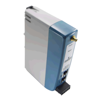
July 2017 Section 1 Introduction ™ ® The Emerson Wireless 1410 Gateway connects WirelessHART self-organizing networks with host ® systems and data applications. Modbus communications over RS-485 or Ethernet provide universal ™ integration and system interoperability. The optional OPC or EtherNet/IP... -
Page 10: 1Section 1: Introduction
Introduction Reference Manual 00809-0200-4410, Rev BC July 2017 Section outline This manual will help to install, configure, operate, and maintain the Gateway. Section 1: Introduction This section introduces the product and describes what components may be found in the box. It also includes details for services and support as well as return and disposal of the product. -
Page 11: Overview
Verify the operating atmosphere of the gateway is consistent with the appropriate hazardous locations certifications. ™ Do not make or break connections to the Emerson 1410 Wireless Gateway (Gateway) while circuits are live unless the area is know to be non-hazardous. -
Page 12: System Requirements
Initial Connection Reference Manual 00809-0200-4410, Rev BC July 2017 System requirements The following requirements apply to the PC/laptop used to configure the Gateway. Additional requirements may apply if using the Security Setup Utility or AMS Wireless Configurator. See Section 4: Software Setup page 21 for more information. -
Page 13: Connections And Power
Reference Manual Initial Connection 00809-0200-4410, Rev BC July 2017 Table 2-1. Default IP Addresses Gateway PC/laptop Subnet Ethernet 1 192.168.1.10 192.168.1.12 255.255.255.0 Ethernet 2 192.168.2.10 192.168.2.12 255.255.255.0 2.3.2 Connections and power Physically connect the PC/laptop to the Gateway with an Ethernet cable by connecting one end to the Ethernet port on the back of the PC/laptop. -
Page 14: Configure The Gateway
Initial Connection Reference Manual 00809-0200-4410, Rev BC July 2017 2.3.3 Configure the Gateway It is now possible to log into the Gateway for the first time and begin configuration for placement on a live control network. The following items need to be configured: Security Passwords ... - Page 15 Antivirus and other software tools are not included in the Gateway firmware. These software tools should be installed on any machine connected to the Gateway. Emerson bundles the latest software patches into our standard Gateway firmware updates. These software patches are not anti-malware or anti-virus tools in any sense of the word, but do provide the latest in security protection.
-
Page 16: Time Settings
Initial Connection Reference Manual 00809-0200-4410, Rev BC July 2017 Time settings The Gateway is the timekeeper for the WirelessHART network, so it is imperative that the Gateway’s time is accurate for timestamp data to be meaningful. Time settings can be found by navigating to System Set- tings>Gateway>Time as shown in Figure 2-2 on page Gateway time settings and time stamps are stored internally as UTC time. - Page 17 Reference Manual Initial Connection 00809-0200-4410, Rev BC July 2017 TCP/IP network settings Use caution when making changes to the TCP/IP network settings. If they are lost or entered incorrectly, the Gateway will require a factory reset (see“Resetting to factory defaults” on page 11).
-
Page 18: System Backup
Initial Connection Reference Manual 00809-0200-4410, Rev BC July 2017 To change the TCP/IP Network Settings: 1. Navigate to System Settings>Ethernet Communication. 2. Select Specify an IP address (recommended). 3. Enter the following: Hostname Domain Name IP Address Netmask ... -
Page 19: Resetting To Factory Defaults
Reference Manual Initial Connection 00809-0200-4410, Rev BC July 2017 2.3.6 Resetting to factory defaults In the event that the user name, password, or IP address of the Gateway is lost, the Gateway can be restored to factory defaults by the procedure below. Note Following this procedure will cause the network to reform and all configuration parameters will be reset to factory defaults. - Page 20 Initial Connection Reference Manual 00809-0200-4410, Rev BC July 2017 Initial Connection...
-
Page 21: Overview
persons. Overview ™ This section describes how to properly mount the Emerson Wireless 1410 Gateway (Gateway) and make electrical connections, including electrical wiring, grounding, and host system connections. This section also describes how to mount the optional remote antenna. -
Page 22: Physical Description
Mounting and Connection Reference Manual 00809-0200-4410, Rev BC July 2017 3.1.2 Physical description The Gateway electronics is enclosed in a polymer housing. The front of the enclosure has connections for power, Ethernet, and serial communications. The unit is designed to be mounted on a DIN rail inside an electronic enclosure. -
Page 23: Remote Antenna
If the supplied remote mount antenna kit is not installed per these instructions, Emerson is not responsible for wireless performance or non-compliance with spectrum regulations. - Page 24 Mounting and Connection Reference Manual 00809-0200-4410, Rev BC July 2017 Installation of WL2/WN2 option 1. Mount the antenna on a 1.5- to 2-in. pipe mast using the supplied mounting equipment. 2. Connect the lightning arrestor directly to the bottom of the user supplied enclosure. 3.
-
Page 25: Connections
Reference Manual Mounting and Connection 00809-0200-4410, Rev BC July 2017 Figure 3-4. Applying Coaxial Sealant to Cable Connections Table 3-1. Remote Antenna Kit Options Kit option Antenna Cable 1 Lightning arrestor Wavelength dipole Head mount, jack to plug omni-directional 50 ft (15,2 m) LMR-400 Gas discharge tube +6 dB Gain 0.5 dB insertion loss... -
Page 26: Rs-485
Mounting and Connection Reference Manual 00809-0200-4410, Rev BC July 2017 Figure 3-5. Gateway Terminal Block Power Reset A+ B- A. 5-screw terminal block B. 24 VDC (nominal) power input ® C. Serial Modbus Ethernet connections should use Cat5e shielded cable to connect to an Ethernet hub, switch, or router. The maximum cable length should not exceed 328 ft (100 m). -
Page 27: Terminating Resistors
Reference Manual Mounting and Connection 00809-0200-4410, Rev BC July 2017 3.4.4 Terminating resistors Three DIP switches are provided to enable various terminating resistors to the RS-485 data bus. The switches are found inside the electronics housing, located behind an access slot on the upper right side. The switches number bottom to top 1 through 3 and the upward position is ON. -
Page 28: Power
Mounting and Connection Reference Manual 00809-0200-4410, Rev BC July 2017 3.4.5 Power The Gateway is designed to be powered by 24 VDC (nominal) Class 2 supply and requires 250 mA of current. The positive and negative connections are depicted on the diagram shown in Figure 3-6 on page The wiring should include an external power shut-off switch or circuit breaker that is located near the... -
Page 29: Overview
This section discusses the installation and setup of the optional software included with the Emerson Wireless 1410 Gateway (Gateway). This software is not required for the wireless field network to operate; however, it will aid in secure host integration as well as wireless field device configuration. The following table describes what items are installed and on which disk they can be found. -
Page 30: Software Installation
Software Setup Reference Manual 00809-0200-4410, Rev BC July 2017 Table 4-3. Supported Operating Systems Operating system Version ™ Windows Professional, Service Pack 3 Windows Server 2003 Standard, Service Pack 2 Windows Server 2003 R2 Standard, Service Pack 2 Windows Server 2008 Standard, Service Pack 2 Windows Server 2008 R2 Standard, Service Pack 1... -
Page 31: Security Setup Utility
Reference Manual Software Setup 00809-0200-4410, Rev BC July 2017 Security setup utility The Security Setup Utility enables secure communications between the Gateway and host system, asset management software, data historians, or other applications. This is done by encrypting the standard ®... -
Page 32: Setup
Software Setup Reference Manual 00809-0200-4410, Rev BC July 2017 4.4.1 Setup In the Security Setup Utility add a new proxy for each Gateway based on the communication protocol that is being used. For example, add an OPC proxy for each Gateway that is communicating OPC. Use the following procedure to add a new proxy in the Security Setup Utility: 1. -
Page 33: Ams Wireless Configurator
Reference Manual Software Setup 00809-0200-4410, Rev BC July 2017 AMS Wireless Configurator AMS Wireless Configurator helps deploy and configure wireless field devices. It provides an integrated ® operating environment that leverages the full capabilities of WirelessHART , including embedded data trending, charting, and graphical display capabilities provided by enhanced EDDL technology. -
Page 34: Licensing And Credits
Software Setup Reference Manual 00809-0200-4410, Rev BC July 2017 Figure 4-3. Wireless Network in the Network Configuration Use the following procedure to configure a HART modem for AMS Wireless Configurator: 1. Open the Network Configuration application. 2. Select Add… This is shown in Figure 4-3. -
Page 35: Overview
EtherNet/IP ............. . .page 35 Overview ™ This section describes how to connect the Emerson Wireless 1410 Gateway (Gateway) to a host system and integrate data gathered from the field device network. It covers network architectures, security, and data mapping. Network architecture Physical connection types are important when determining the network architecture and what protocols can be used for integration. -
Page 36
Host Integration Reference Manual 00809-0200-4410, Rev BC July 2017 RS485 (serial) An RS485 connection supports Modbus RTU protocol. Using this connection type, the Gateway is wired to an RS485 bus which typically leads to a serial I/O card or Modbus I/O card (see
Figure 5-2). -
Page 37: Internal Firewall
Reference Manual Host Integration 00809-0200-4410, Rev BC July 2017 Internal firewall The Gateway supports an internal firewall that inspects both incoming and outgoing data packets. TCP ports for communication protocols are user configurable, including user specified port numbers and the ability to disable ports. - Page 38 Host Integration Reference Manual 00809-0200-4410, Rev BC July 2017 Figure 5-4. Modbus Communications Page One Modbus Address: When this option is selected, this address is used by the Gateway for Modbus RTU communications. Multiple Modbus Addresses: When this option is selected, a new column for address will appear on the Modbus mapping page.
-
Page 39: Register Mapping
Reference Manual Host Integration 00809-0200-4410, Rev BC July 2017 Floating point representation: This setting determines if the Gateway uses floating point values or integer values. There are three options for this setting. Float: This option uses 32-bit floating point values. ... - Page 40 Host Integration Reference Manual 00809-0200-4410, Rev BC July 2017 Figure 5-5. Modbus Register Map Page To add a new data point to the Modbus register map: 1. Select New entry. 2. Complete all of the table entries for the new data point (note that the entry columns may vary based on the Modbus communications settings).
-
Page 41
Reference Manual Host Integration 00809-0200-4410, Rev BC July 2017 Point Name is entered as
. Point Name can be entered using the list of values (…) or manually entered. The following table gives a list of standard device parameters which may be considered for Modbus register mapping. - Page 42 Reference Manual Host Integration 00809-0200-4410, Rev BC July 2017 Predefined Modbus registers In addition to user configurable parameters, the Gateway also supports a list of predefined Modbus registers with diagnostics and test parameters. The following table is a list of the predefined Modbus registers.
-
Page 43: Ethernet/Ip
EtherNet/IP communication settings can be found by navigating to System Settings>Protocols>Ethernet/IP. Note EtherNet/IP can be integrated with any approved EtherNet/IP ODVA member. Other protocols such as ™ HART-IP are still functional within the Gateway. Refer to Emerson Wireless Gateway Product Data Sheet for ordering options. Host Integration... - Page 44 Host Integration Reference Manual 00809-0200-4410, Rev BC July 2017 Figure 5-6. EtherNet/IP Communications Page Table 5-3. System Settings>Protocols>Ethernet/IP Terms Description Assembly Object Type EtherNet/IP use Static assembly object. EtherNet/IP TCP Port The TCP Port used to access EtherNet/IP TCP data directly from the Gateway. EtherNet/IP UDP Ports The UDP Ports used to access EtherNet/IP UDP data directly from the Gateway.
- Page 45 Reference Manual Host Integration 00809-0200-4410, Rev BC July 2017 Table 5-3. System Settings>Protocols>Ethernet/IP Terms Description This is the value returned by the Gateway if the EtherNet/IP master requests a Unmapped parameter read response register with no data assigned to it (empty register). It is recommended this be set to zero fill to prevent errors.
- Page 46 Reference Manual Host Integration 00809-0200-4410, Rev BC July 2017 Table 5-4. Summary of Terms Used for EtherNet/IP Mapping Page Terms Description Input Instance EtherNet/IP Input Static Assembly Instance - 496 bytes Output Instance EtherNet/IP Output Static Assembly Instance - 496 bytes Member EtherNet/IP Instance Member in which data will get produced or consumed Point Name...
-
Page 47: Service Support
Return of materials ..............page 42 Service Support ™ This section provides basic troubleshooting tips for the Emerson Wireless Field Network. To receive technical support by phone:... -
Page 48: Troubleshooting
Right click on wireless network and select rebuild hierarchy. Gateway Install latest device support files from AMS Wireless Configurator. Go to Wireless device appears Emerson.com/Automation/AMS. with red HART symbol Verify whether current or historical information is being displayed. This setting is Device configuration displayed at the bottom of each device configuration screen. - Page 49 Verify network firewall and port settings. ™ EtherNet/IP Verify connection is established with EtherNet/IP. Navigate to SETUP > The Gateway is not SECURITY > PROTOCOLS. publishing the parameters Reference Emerson Wireless Integration Manual: Installation manual to ® connect to an Allen-Bradley system. Troubleshooting...
-
Page 50: Return Of Materials
To expedite the return process outside of North America, contact your Emerson representative. Within the United States, call the Emerson Response Center toll-free number 1 800 654 7768. The center, which is available 24 hours a day, will assist you with any needed information or materials. - Page 51 Glossary 00809-0200-4410, Rev BC July 2017 Section 7 Glossary ™ This glossary defines terms used throughout this manual those appearing in the Emerson Wireless 1410 Gateway (Gateway) web interface. Term Definition Access Control A list of all devices that are approved to join the network. Each device will also have a List unique join key.
- Page 52 Glossary Reference Manual 00809-0200-4410, Rev BC July 2017 Term Definition Network I.D. Numeric code that associates wireless field devices to the Gateway. This code must be identical in the device and the gateway. Network Manager Operational function within the Wireless Gateway that automatically handles all device connections and scheduling of wireless data.
-
Page 53: Ordering Information
Accessories and spare parts ............page 51 A.1 Ordering information ™ Table A-1. Emerson Wireless 1410 Gateway Ordering Information The starred offerings (★) represent the most common options and should be selected for best delivery. The non-starred offerings are subject to additional delivery lead time. Model Product description ®... -
Page 54: Specifications And Reference Data
Oil and gas options ★ Oil and gas monitor page Typical model number: 1410 A 2 D5 WX2 NA Single active 10/100 baseT Ethernet port with RJ45 connector. Additional ports disabled. Dual active 10/100 baseT Ethernet ports with RJ45 connectors. -
Page 55: Functional Specifications
Specifications and Reference Data Reference Manual July 2017 00809-0200-4410, Rev BC A.2 Functional specifications A.2.7 Antenna 2 dBi rubber dipole with SMA connector A.2.1 Input voltage SMA connection is female 10.5–30 VDC Class 2 power supply A.3 Physical specifications A.2.2 Current draw A.3.1 Weight Operating current draw is based on 3.0 Watt power consumption. -
Page 56: Modbus
Gateway and connections to host instances are user configurable. EtherNet/IP specifications systems and the self-organizing network. are managed and distributed by ODVA. For details on A.6.3 Self-organizing network capabilities, see the Emerson Wireless Gateway to Allen-Bradley Integration Manual AES-128 Encrypted WirelessHART, including individual Emerson.com/Rosemount. -
Page 57: Dimensional Drawings
(164,0) A. RF connector on Emerson Wireless 1410 Gateway is an SMA female. Matching RF cable to antenna should be a SMA male. Note: Allow extra space in front of unit for wiring, antenna connector and antenna cable service loop. - Page 58 Reference Manual Specifications and Reference Data July 2017 00809-0200-4410, Rev BC Figure A-3. Remote Omni-Antenna Kit The remote omni-antenna kit includes sealant tape for remote antenna connection, SMA to N-type adapter cable, mounting brackets for the antenna, and lightning arrester. A.
-
Page 59: Accessories And Spare Parts
Specifications and Reference Data Reference Manual July 2017 00809-0200-4410, Rev BC A.8 Accessories and spare parts Table A-2. Accessories Part number Item description ™ AMS Wireless SNAP-ON , 1 Gateway licenses 01420-1644-0001 AMS Wireless SNAP-ON, 5 Gateway licenses 01420-1644-0002 AMS Wireless SNAP-ON, 10 Gateway licenses 01420-1644-0003 AMS Wireless SNAP-ON, 5-10 Upgrade licenses 01420-1644-0004... - Page 60 Reference Manual Specifications and Reference Data July 2017 00809-0200-4410, Rev BC Specifications and Reference Data...
-
Page 61: European Directive Information
Nearly every country requires this type of product The US National Electrical Code (NEC) and the Canadian ™ certification. Emerson is working with governmental Electrical Code (CEC) permit the use of Division marked agencies around the world to supply fully compliant... -
Page 62: Usa
Special Condition for Safe Use (X): 3. The equipment is not capable of withstanding the 500 1. When installed as Division 2 equipment, the Emerson V electrical strength test as defined in clause 6.5.1 of Wireless 1410 Gateway shall be mounted within a EN 60079-15: 2010. -
Page 63: Eac - Belarus, Kazakhstan, Russia
Product Certifications Reference Manual July 2017 00809-0200-4410, Rev BC 4. When fitted, the surface resistivity of the remote antenna is greater than 1 GΩ. To avoid electrostatic charge build-up, it must not be rubbed with a dry cloth or cleaned with solvents. Note Currently not available for 1410D Gateway option. - Page 64 Product Certifications Reference Manual July 2017 00809-0200-4410, Rev BC Product Certifications...
- Page 66 Terms and Conditions of Sale page. +65 6777 0947 The Emerson logo is a trademark and service mark of Emerson Electric Co. [email protected] DeltaV, Ovation, SNAP-ON, Rosemount, and Rosemount logotype are trademarks of Emerson. Allen-Bradley is registered by Rockwell Automation.