Emerson 1410S Reference Manual
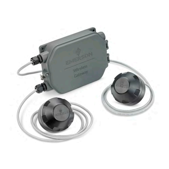
Wireless gateway and smart antenna
Hide thumbs
Also See for 1410S:
- Reference manual (78 pages) ,
- Quick start manual (48 pages) ,
- Reference manual (64 pages)

Related Manuals for Emerson 1410S


Summary of Contents for Emerson 1410S
- Page 1 Reference Manual 00809-0600-4410, Rev AA May 2020 Emerson Wireless 1410S Gateway and 781S Smart Antenna...
-
Page 3: Table Of Contents
3.2 Emerson Gateway 1410S2 installation overview................ 21 3.3 Power specifications........................22 3.4 Mounting the Emerson 1410S2 Gateway................... 23 3.5 Mounting the Emerson 781S Smart Antenna................24 3.6 Connecting the Emerson 1410S to the 781S Smart Antennas............ 25 3.7 Verify operations........................32 Chapter 4 Commissioning......................35 4.1 Overview........................... - Page 4 Redundant Gateway systems................... 55 B.1 Overview........................... 55 B.2 Requirements..........................55 B.3 Setup............................55 B.4 Diagnostics ..........................61 B.5 Gateway replacement........................63 Appendix C Power specifications....................65 C.1 Dual mode upgrades......................... 65 C.2 IEC 62734 Network........................65 C.3 IEC 62734 Device support......................66 Emerson.com...
-
Page 5: Chapter 1 Introduction
May 2020 Introduction Emerson Wireless 1410S Gateway 781S Smart Antenna The Emerson Wireless 1410S Gateway and 781 Smart Antenna combine to create the ® main access point of a wireless network. Modbus communications over RS-485 or Ethernet provide universal integration and system interoperability. The optional OPC or ™... - Page 6 Introduction Reference Manual May 2020 00809-0600-4410 Emerson.com...
-
Page 7: Chapter 2 Configuration
The 781S Smart Antenna should be positioned vertically and be approximately 6 ft. (2 m) from large structures or buildings to allow for clear communication to other devices. If using two Emerson 781S Smart Antennas, each should be mounted at least 3 ft. (0.91 m) from one another. - Page 8 Gateway are operationally equivalent and the following instructions are applicable to both. Powering the Gateway For the Emerson 1410S, bench top power will be needed to power the Gateway by wiring a 10.5–30 VDC (24 VDC if configured with I.S. barriers) power source. See Power...
- Page 9 Procedure 1. Click the Internet Access icon on the bottom right of the screen. 2. Select the Network and Sharing Center. 3. Select Local Area Connection. 4. Select Properties. 5. Select Internet Protocol Version 4 (TCP/IPv4) → Properties. Emerson 1410S/781S...
- Page 10 8. In the Subnet mask field, enter 255.255.255.0. 9. Select OK for both the Internet Protocol (TCP/IP) Properties window and the Local Area Connection Properties window. 2.3.3 Windows 10 Procedure 1. Select the network icon in the lower right corner. 2. Select the Network settings link. Emerson.com...
- Page 11 Reference Manual Configuration 00809-0600-4410 May 2020 3. Select Change adapter options. Emerson 1410S/781S...
- Page 12 If the PC/laptop is from another network, record the current IP address and other settings so the PC/laptop can be returned to the original network after the Gateway has been configured. 6. Select the Use the following IP address button. Emerson.com...
- Page 13 255.255.255.0 192.168.2.10 192.168.2.12 255.255.255.0 2.3.4 Disable proxies Use these steps to disable proxies. Procedure 1. Open web browser. 2. Navigate to Tools → Internet Options → Connections → LAN Settings (may be a different process for other browsers). Emerson 1410S/781S...
- Page 14 WirelessHART and ISA100 networks. Procedure 1. Access the WirelessHART default web page for the Gateway at https:// 192.168.1.10. You will have to configure both networks individually. a) Log on as Username: admin b) Type in password: default Emerson.com...
- Page 15 There are four role-based user accounts for the Gateway with varying levels of access. The access can be changed on the System Settings → Users → User Accounts by the admin user. The figure below displays this access. Emerson 1410S/781S...
- Page 16 It is suggested the default security settings in System Settings → Users → User Options be changed to the local IT best practices or the “Normal” setting after initial login. Strong or custom settings are available for more robust passwords. Emerson.com...
- Page 17 Network Time Protocol (NTP) is recommended for the best network performance because it always adjusts time to match the network time server. 2.3.9 To change the TCP/IP network settings Procedure 1. Navigate to System Settings → Gateway → Ethernet Communication. Emerson 1410S/781S...
- Page 18 4. Enter a save location and file name. 5. Select Save. 6. Select Return to form. Note System Backup contains user passwords and keys used for encrypting communication. Store downloaded system backups in a secure location. The actual files are also encrypted. Emerson.com...
- Page 19 Procedure 1. Turn off power to the Gateway. 2. Locate the Reset switch label on the back of the Gateway. For the Emerson 1410S2 modular housing, the switch is located inside the Gateway housing cover on the DIP switch panel board. The reset switch is labeled switch 4.
- Page 20 Configuration Reference Manual May 2020 00809-0600-4410 Emerson.com...
-
Page 21: Installing The Gateway
(process control network) as well as the wireless field device network and protects the Gateway from moisture and contamination. It is also best practice to install the Emerson 781S Field Links centrally in the network for the most direct connections for the Gateway. -
Page 22: Power Specifications
Installing the Gateway Reference Manual May 2020 00809-0600-4410 Power specifications Table 3-1: Emerson 1410S Gateway Power Gateway version Non-barrier Barrier Input voltage 10.5 to 30V VDC 24 VDC Power consumption 5 Watts 7.5 Watts At start-up, the power supply must be capable of momentarily sourcing at least twice the operating current. -
Page 23: Mounting The Emerson 1410S2 Gateway
Reference Manual Installing the Gateway 00809-0600-4410 May 2020 Mounting the Emerson 1410S2 Gateway Find a location where the Gateway has convenient access to the host system network (process control network). 3.4.1 Pipe mount Pipe mount The following hardware and tools are needed to mount the Gateway to a 2-in. pipe: •... -
Page 24: Mounting The Emerson 781S Smart Antenna
Figure 3-2: System Architecture Example Mounting location The Emerson Smart Antenna should be mounted in a location that allows convenient access to the host system network (wireless I/O) as well as the wireless field device network. Find a location where the Smart Antenna has optimal wireless performance. -
Page 25: Connecting The Emerson 1410S To The 781S Smart Antennas
There are two main connection configurations for the Emerson 1410S and 781S Smart Antennas: with and without intrinsically safe barriers. The hazardous location approval option of the Emerson 781S determines whether it needs to be installed with barriers. This connection is integrated in the Gateway electronics and can be selected upon order. - Page 26 Installing the Gateway Reference Manual May 2020 00809-0600-4410 provide intrinsic safety and approval for Emerson 781S installation in Div 1/Zone 0 areas. For more information on product approvals, see Reference data. The Gateway enclosure acts as a junction box for wiring connections. The enclosure has five conduit entries for power and communications wiring.
- Page 27 May 2020 3.6.3 Emerson 781S installation A shielded twisted-pair cable is needed for connecting the Emerson 1410S and each 781S Smart Antennas. Each Emerson 781S can be located up to 1312 ft. (400m) from the Emerson 1410S. Figure 3-4: Emerson 1410S Gateway and Single 781S Smart Antenna A.
- Page 28 Installing the Gateway Reference Manual May 2020 00809-0600-4410 Figure 3-5: Emerson 1410S Gateway and Two 781S Smart Antennas A. Emerson Wireless 781S Smart Antenna B. Attach shield pair cable (Belden 3084A or equivalent) C. Emerson Wireless 781S Smart Antenna D. Tape back shield wire and foils E.
- Page 29 3.6.5 Shield grounding The shields of the twisted-pair cables need to be grounded using the grounding terminal on the Emerson 1410S, and it should be taped back on the Emerson 781S side. 3.6.6 Terminating resistors Five DIP switches are provided to enable various terminating resistors to the RS-485 ®...
- Page 30 Switch 2 is connected to a 120 Ω terminating resistor for Modbus connection. This resistor is used to dampen signal reflections on long cable runs. RS-485 specifications indicate that the data bus should be terminated at both ends (Figure 3-7). Emerson.com...
- Page 31 1. Pre standard PoE (Online Power) 2. 802.3af-compliant PoE (15W) 3. 802.3at-compliant PoE Plus (PoE+) (25W) 4. Universal PoE (UPoE) (60W). (New Cisco standard, which Cisco claims is compatible with IEEE 802.3af PoE and IEEE 802.3at PoE +) Emerson 1410S/781S...
-
Page 32: Verify Operations
PoE FAQs What do I have to There is no specific option code for PoE. All 1410S Gateways have do to order IEEE PoE PoE. The only configuration needed is to flip DIP switch 5. Turning on a 1410S the switch “ON”... - Page 33 Join Key information. Once the field devices are powered, they will appear on the wireless network and communications can be verified under the Explore tab using the web interface. The time needed for the network to form will depend on the number of devices. Emerson 1410S/781S...
- Page 34 Installing the Gateway Reference Manual May 2020 00809-0600-4410 Emerson.com...
-
Page 35: Commissioning
Commissioning Overview This section discusses the installation and setup of the optional software included with the Emerson Wireless Gateway. The following table describes what items are installed and on which disk they can be found. Table 4-1: Software Applications Name... -
Page 36: Software Installation
This is done by ® encrypting the standard data protocols (AMS Wireless Configurator, Modbus TCP, and OPC) used by the Gateway and making them available through various proxies within the Emerson.com... -
Page 37: Ams Wireless Configurator
® WirelessHART , including embedded data trending, charting, and graphical display capabilities provided by enhanced EDDL technology. • Display and modify device configuration • View device diagnostics • View process variables Emerson 1410S/781S... -
Page 38: Licensing And Credits
Configurator. To display the release notes, navigate to Start → Programs → AMS Wireless Configurator → Help. Licensing and credits The latest licensing agreements are included on each disk of the software pack. This product includes software developed by the OpenSSL Project for use in the OpenSSL Toolkit. Emerson.com... -
Page 39: Operation And Maintenance
5-1) using a network switch, router, or hub. Often there are two networks for redundancy purposes. Figure 5-1: Ethernet Architecture A. Engineering station B. Primary control network C. Secondary control network D. Controller and I/O E. Wireless Gateway Emerson 1410S/781S... -
Page 40: Modbus
It is import that the Modbus communication settings in the Gateway match the settings in the Modbus master or client. Please refer to host system documentation for more information on how to configure these settings. The Modbus communication settings can be found by navigating to System Settings → Protocols → Modbus. Emerson.com... - Page 41 This setting determines parity (none, even, or odd) used for error checking purposes. This setting is only required for Modbus RTU. Stop Bits This setting determines the number (1 or 2) of stop bits used when ending a message. This setting is only required for Modbus RTU. Emerson 1410S/781S...
- Page 42 Use global scale gain This setting determines if a global gain and offset is applied for and offset? scaled integers or if each value has a unique gain and offset. Unique gain and offsets are found on the Modbus Mapping page. Emerson.com...
- Page 43 Global scale offset This value is added to the data values for the purpose of scaling integers. If global scaling is not selected, an offset value will be available for each separate data value on the Modbus Mapping page. Emerson 1410S/781S...
- Page 44 Operation and maintenance Reference Manual May 2020 00809-0600-4410 Emerson.com...
-
Page 45: Chapter 6 Troubleshooting
Troubleshooting 00809-0600-4410 May 2020 Troubleshooting Service support This section provides basic troubleshooting tips for the Emerson Smart Wireless Field Network. To receive technical support by phone: Global Service Center Software and Integration support United States-1 800 833 8314 International-63 2 702 1111... -
Page 46: Initial Connection: Cannot Find Gateway After Changing Ip Address
Possible cause: Incorrect credentials Recommended actions 1. Verify the user name and password (administrator user name is "admin", default password is "default"). 2. If unable to connect, consider resetting the Gateway. AMS Wireless Configurator: Gateway does not appear in AMS Wireless Configurator Emerson.com... -
Page 47: Ams Wireless Configurator: Wireless Devices Do Not Appear Under The Gateway
HART symbol Possible cause: Non-current device support files Recommended actions 1. Navigate to Emerson's AMS Device Manager product page. 2. Install latest device support files from AMS Wireless Configurator. AMS Wireless Configurator: Device configuration items are grayed out... -
Page 48: Wireless Field Devices: Wireless Device Does Not Appear On The Network
1. Verify the total number of devices on the network (25 maximum). 2. Go to SETUP → NETWORK → BANDWIDTH and click Analyze bandwidth. Any changes will require the network to reform. 3. Reduce the update rate for the device. Emerson.com... -
Page 49: Modbus Communications: Cannot Communicate Using Modbus ® Rtu
Navigate to SETUP → MODBUS → COMMUNICATIONS. 3. Verify Modbus register mapping in the Gateway. a) Log on to the Gateway. b) Navigate to SETUP → MODBUS → MAPPING. 6.15 Modbus communications: Cannot ® communicate using secure Modbus Emerson 1410S/781S... -
Page 50: Opc Communications: Opc Application Cannot Find A Gateway Opc Server
OPC communications: Gateway OPC server does not show any Gateways Possible cause: Proxy not configured Recommended actions Configure an OPC proxy for the Gateway (see Security setup utility). 6.18 OPC communications: Gateway OPC server does not show any data tags Emerson.com... -
Page 51: Ethernet/Ip ™ : Gateway Is Not Publishing The Parameters
To expedite the return process outside of North America, contact your Emerson representative. Within the United States, call the Emerson Response Center toll-free number 1 800 654 7768. The center, which is available 24 hours a day, will assist you with any needed information or materials. - Page 52 If the product being returned was exposed to a hazardous substance as defined by OSHA, a copy of the required Material Safety Data Sheet (MSDS) for each hazardous substance identified must be included with the returned goods. Emerson.com...
-
Page 53: Appendix A Reference Data
Reference data 00809-0600-4410 May 2020 Reference data Ordering information, specifications, and drawings To view current Emerson 1410S and 781S ordering information, specifications, and drawings, follow these steps: Procedure 1. Navigate to the product page for Emerson 1410S and 781S. 2. Scroll as needed to the green menu bar and click Documents & Drawings. - Page 54 Product Data Sheet 00813-0600-4410, Rev AA April 2020 Emerson Wireless 1410S Gateway with 781S Smart Antenna ■ Gateway connects the WirelessHART ® self-organizing networks with any host system ■ Easy configuration and management of self-organizing networks ■ Easy integration into control systems and data applications through serial and Ethernet connections ■...
-
Page 55: Appendix B Redundant Gateway Systems
■ All wireless devices are authenticated so you know exactly what is on your network ■ Third party security certifications including Achilles and FIPS-197 certification demonstrate Emerson's commitment to security ■ Complete control of your network using the Gateway secure web interface SmartPower solutions ■... - Page 56 ■ The integrated web interface allows easy configuration of the wireless network and data integration without the need to install additional software ■ Complimentary AMS Wireless Configurator software provides Emerson Device dashboards to configure WirelessHART devices and view diagnostic data ■...
- Page 57 Emerson Wireless 1410S April 2020 Emerson Wireless 1410S Gateway ordering information VIEW PRODUCT > Online Product Configurator Many products are configurable online using our Product Configurator. Select the Configure button or visit our website to start. With this tool's built-in logic and continuous validation, you can configure your products more quickly and accurately.
- Page 58 Description ★ Zone 0 / Div 1: Emerson 781S Smart Antenna may be installed in Zone 0/1/2 & Class I Div 1/2 ★ Zone 2 / Div 2: Emerson 781S Smart Antenna may be installed in Zone 2 & Class I Div 2...
- Page 59 Emerson Wireless 1410S April 2020 Code Description ★ Canada Division 2 Non-Incendive & Zone 2 Type ec ★ ATEX Type ec ★ IECEx Type ec ★ ATEX Dust ★ IECEx Dust ★ No approvals Additional options Conduit adapters Code Description ★...
- Page 60 Emerson Wireless 1410S April 2020 Code Description Kuwait, Qatar, Saudi Arabia, UAE Bahrain, Belarus, Israel, Tunisia, Uzbekistan Russian Federation India Japan Indonesia Taiwan China Korea Malaysia Note By selecting a Cisco spectrum domain, you are selecting an IW6300 Wi-Fi access point and will need to also select an option from the following Cisco option tables.
-
Page 61: Diagnostics
Emerson Wireless 1410S April 2020 Emerson Wireless 781S Smart Antenna ordering information VIEW PRODUCT > Online Product Configurator Many products are configurable online using our Product Configurator. Select the Configure button or visit our website to start. With this tool's built-in logic and continuous validation, you can configure your products more quickly and accurately. - Page 62 Emerson Wireless 1410S April 2020 Wireless protocol and operating frequency Code Description ★ WirelessHART, user configurable transmit rate, 2.4 Hz DSSS, IEC 62951 ★ ISA100, user configurable transmit rate, 2.4HZ DSSS, IEC 62734 Communication Code Description ★ Legacy RS485 communication...
-
Page 63: Gateway Replacement
Emerson Wireless 1410S April 2020 Specifications Emerson Wireless 1410S Gateway Functional specifications Power Intrinsically Safe Output Option A: 24 VDC Intrinsically Safe Output Option B: 10.5-30 VDC For best results, use a high quality industrial galvanically isolated power supply. Current draw: Intrinsically Operating current draw is based on 7 Watts power consumption. - Page 64 Emerson is not in a position to evaluate or guarantee the compatibility of the process fluid or other process parameters with the product, options, configuration or materials of construction selected.
-
Page 65: Appendix C Power Specifications
Emerson Wireless 1410S April 2020 Materials of construction Enclosure housing Engineered polymer Mounting Mounting brackets also permit remote mounting Size Diameter 3.7 in. (9.4 cm) Weight 2.4 lb. (1.1 kg) Enclosure ratings (Emerson 781S) Type 4X and IP66/67 rated Performance specifications EMC performance Meet all industrial environment requirements of EN61326 and NAMUR NE-21. -
Page 66: Iec 62734 Device Support
Emerson Terms and Conditions of Sale are available upon request. The Emerson logo is a Facebook.com/Rosemount trademark and service mark of Emerson Electric Co. Rosemount is a mark of one of the Youtube.com/user/RosemountMeasurement Emerson family of companies. All other marks are the property of their respective owners. - Page 67 Reference data Reference Manual May 2020 00809-0600-4410 Emerson.com...
- Page 68 Quick Start Guide 00825-0600-4410, Rev AA March 2020 Emerson Wireless 1410S Gateway...
- Page 69 Safety messages NOTICE This guide provides basic guidelines for the Emerson Wireless 1410S Gateway. It does not provide instructions for diagnostics, maintenance, service, or troubleshooting. Refer to the Emerson Wireless Gateway 1410S Reference Manual for more information and instructions. The manuals and this guide are available electronically on Emerson.com/Rosemount.
-
Page 70: Wireless Planning
This will result in a simpler and faster network installation. Gateway redundancy If the wireless Gateway was ordered with redundancy (Gateway Redundancy code RD), refer to Appendix D in the Emerson Wireless Gateway Reference Manual for additional installation instructions. Quick Start Guide... -
Page 71: Pc Requirements
Configuration of the Gateway is done through a secure web interface. Recent versions of the following browsers are supported: ™ • Chrome browser ® • Mozilla Firefox • Microsoft Edge Hard disk space • AMS Wireless Configurator: 1.5 GB • Gateway Setup CD: 250 MB Emerson.com... -
Page 72: Initial Connection And Configuration
To configure the Gateway, a local connection between a computer and the Gateway needs to be established. Powering the Gateway For the Emerson 1410S, bench top power will be needed to power the Gateway by wiring a 10.5–30 VDC (24 VDC if configured with I.S. barriers) power source. - Page 73 Connect the PC/laptop to the Ethernet 1 (Primary) receptacle on the Gateway using an Ethernet cable. Windows 7 Procedure 1. Click the Internet Access icon on the bottom right of the screen. Figure 3-2: Internet Access 2. Select the Network and Sharing Center. 3. Select Local Area Connection. Emerson.com...
- Page 74 March 2020 Quick Start Guide Figure 3-3: Local Area Connection 4. Select Properties. 5. Select Internet Protocol Version 4 (TCP/IPv4) then select Properties. Figure 3-4: Internet Protocol Version 4 (TCP/IPv4) Note If the PC/laptop is from another network, record the current IP address and other settings so the PC/laptop can be returned to the original network after the Gateway has been configured.
- Page 75 Figure 3-5: IP Address 7. In the IP address field, enter 192.168.1.12 (DeltaV Ready enter 10.5.255.12). 8. In the Subnet mask field, enter 255.255.255.0. 9. Select OK for both the Internet Protocol (TCP/IP) Properties window and the Local Area Connection Properties window. Emerson.com...
- Page 76 March 2020 Quick Start Guide Windows 10 Figure 3-6: Network Settings Procedure 1. Select the network icon in the lower right corner. 2. Select the Network settings link. 3. Select Change adapter options. Quick Start Guide...
- Page 77 Quick Start Guide March 2020 Figure 3-7: Change Adapter Options 4. Right click the network interface connection that the Gateway is plugged into, and select Properties. 5. Select Internet Protocol Version 4 (TCP/IPv4) then select Properties. Emerson.com...
- Page 78 March 2020 Quick Start Guide Figure 3-8: Internet Protocol Version 4 (TCP/IPv4) Note If the PC/laptop is from another network, record the current IP address and other settings so the PC/laptop can be returned to the original network after the Gateway has been configured. 6.
- Page 79 9. Select OK for both the Internet Protocol (TCP/IP) Properties window and the Local Area Connection Properties window. Note Connecting to the Gateway's secondary Ethernet port will require different network settings. Table 3-1: Network Settings Gateway PC/laptop/ Subnet tablet Ethernet 1 192.168.1.10 192.168.1.12 255.255.255.0 Ethernet 2 192.168.2.10 192.168.2.12 255.255.255.0 Emerson.com...
- Page 80 March 2020 Quick Start Guide Disable proxies This procedure may be necessary when using a Chrome browser with Windows operating systems. Procedure 1. Open web browser. 2. Navigate Settings >Advanced. 3. In the System section, click Open proxy settings. Example Configure the Gateway To complete initial configuration for the Gateway, follow the steps below.
- Page 81 Figure 3-11: Ethernet Communication b) Restart application at System Settings > Gateway > Backup and Restore > Restart Apps. Note Resetting applications will temporarily disable communications with field devices. 3. Disconnect the power and Ethernet cable from the Gateway. Emerson.com...
-
Page 82: Physical Installation
Gateway mounting bracket, and through the washer plate. 2. Use a 1/2-in. socket-head wrench to fasten the nuts to the u-bolt. 3. Repeat for the second u-bolt and the lower mounting holes. Figure 4-1: Emerson 1410S2 Mounting Quick Start Guide... - Page 83 1. Drill four 3/8-in. (9,525 mm) holes spaced 3.06-in. (77 mm) apart horizontally and 11.15-in. (283 mm) apart vertically in the support bracket, corresponding with the holes on the Gateway mounting bracket. 2. Using a 1/2-in. socket-head wrench, attach the Gateway to the support bracket with four 15/16-in. bolts. Emerson.com...
- Page 84 March 2020 Quick Start Guide Connecting the Emerson 1410S with 781S Smart antennas Figure 4-2: Emerson 1410S and 781S Installation A. Emerson Wireless 1410S Gateway B. Terminal connections C. Shield pair cable D. Emerson Wireless 781S Smart Antenna E. Power output F.
- Page 85 Quick Start Guide March 2020 Terminating resistors Please reference the Emerson 1410S Gateway and 781S Smart Antenna Reference Manual for configuration of the DIP switches. Three DIP switches are provided to enable termination and biasing resistors to the serial Modbus connection. The switches are found in the electronics housing located above the terminal connections.
-
Page 86: Software Installation (Optional)
D:\SETUP.EXE (where D is the CD/DVD drive on the PC) and select OK. For more information about the Security Setup Utility and AMS Wireless Configurator, see the Emerson 1410S Gateway and 781S Smart Anetennas Reference Manual. Quick Start Guide... -
Page 87: Verify Operations
Gateway (found on the Network Setting page). Once the field devices are powered, they will appear on the wireless network and communications can be verified under the Explore tab using the web interface. The time needed for the network to form will depend on the number of devices. Emerson.com... -
Page 88: Product Certifications
All wireless devices require certification to ensure they adhere to regulations regarding the use of the RF spectrum. Nearly every country requires this type of product certification. Emerson is working with governmental agencies around the world to supply fully compliant products and remove the risk of violating country directives or laws governing wireless device usage. - Page 89 1. The enclosure’s polyurethane paint finish may constitute an electrostatic hazard. Care should be taken to protect it from external conditions conducive to the build-up of electrostatic charge on such surfaces. The equipment must only be cleaned with a damp cloth. Emerson.com...
- Page 90 March 2020 Quick Start Guide 2. The equipment is not capable of withstanding the 500V electrical strength test as defined in clause 6.1 of EN 60079-7:2015+ A1:2018 and 6.3.13 EN 60079-11:2012. This must be taken into account during installation. ND ATEX Dust-Ignition Proof with Intrinsically Safe Outputs to Zone 2 Certificate SGS20ATEX0036X Markings II 3D (3G) Ex tc [ic IIC Gc] IIIC T90°C Dc (-40°C ≤...
- Page 91 IEC 60950 series, IEC 61010-1 or a technically equivalent standard. 3. The equipment is not capable of withstanding the 500V electrical strength test as defined in clause 6.1 of EN 60079-7:2015+ A1:2017. This must be taken into account during installation. Emerson.com...
- Page 92 March 2020 Quick Start Guide NF IECEx Dust-Ignition Proof with Intrinsically Safe Outputs to Zone 0 Certificate IECEx BAS.20. 0022X Markings Ex tc [ia IIC Ga] IIIC T90°C Dc (-40°C ≤ Ta ≤ +65°C) Standards IEC 60079-0: 2017, IEC 60079-7:2015+A1:2017, IEC 60079-11: 2011, IEC 60079-15:2017, IEC 60079-31:2013 Special Conditions for Safe Use (X): 1.
- Page 93 Quick Start Guide March 2020 Declaration of Conformity Emerson.com...
- Page 94 March 2020 Quick Start Guide Quick Start Guide...
- Page 95 Quick Start Guide March 2020 Emerson.com...
-
Page 96: Reference Data
March 2020 Quick Start Guide Reference data For information on product specs, dimensional drawings, ordering information or the complete reference manual, see Emerson.com. Figure 8-1: Hazardous Location Installation Quick Start Guide... - Page 97 The Emerson logo is a Twitter.com/Rosemount_News trademark and service mark of Emerson Electric Facebook.com/Rosemount Co. Rosemount is a mark of one of the Emerson Youtube.com/user/ family of companies. All other marks are the RosemountMeasurement property of their respective owners.
- Page 98 Quick Start Guide 00825-0700-4410, Rev AA March 2020 Emerson Wireless 781S Smart Antenna...
- Page 99 Safety messages NOTICE This guide provides basic guidelines for the Emerson Wireless 781S Smart Antenna. It does not provide instructions for diagnostics, maintenance, service, or troubleshooting. Refer to the Emerson Wireless 1410S Gateway and 781S Smart Antenna Reference Manual for more information and instructions. The manuals and this guide are available electronically on Emerson.com/Rosemount.
- Page 100 March 2020 Quick Start Guide Verify operation......................... 11 Product certifications......................... 12 Reference data........................... 21 Quick Start Guide...
- Page 101 Quick Start Guide Wireless planning Power up sequence The Emerson Wireless Smart Antenna and wireless I/O should be installed and functioning properly before the power modules are installed in any wireless field devices. Wireless field devices should also be powered up in order of proximity from the antenna beginning with the closest.
- Page 102 Quick Start Guide March 2020 Antenna position The Emerson 781S Smart Antennas should be positioned vertically and approximately 3 ft. (1 m) from large structures, buildings, or conductive surfaces to allow for clear communication to other devices. If installing multiple antennas, it is important that the antennas have three feet of horizontal separation from one another.
- Page 103 March 2020 Quick Start Guide Intended use System architecture The Smart Antenna must be used in conjunction with a network manager or network Gateway. The Smart Antenna then functions as a translator between the wired network and a wireless field network. Figure 2-1: Example System Architecture Quick Start Guide...
- Page 104 4. Use a 5/16-in. wrench to tighten the screw into the housing. Figure 3-1: Mounting Power and data wiring The Emerson 781S is completely prewired and only needs to be connected and powered on the Gateway end. The housing is permanently sealed on the Emerson 781S. In the Gateway:...
- Page 105 Quick Start Guide Figure 3-2: Wiring Guide A. Power B. Data Red - positive Blk - negative Wht - RS-485 comm A Blu - RS-485 comm B Figure 3-3: Emerson Wireless 781S A. Power output B. RS-485 comm Quick Start Guide...
- Page 106 Twisted shielded pair cable is generally used to wire the serial connection to the Gateway. The Smart Antenna should be installed in a central location of the wireless field network so that it has the most direct connections to wireless devices as possible. Emerson.com...
- Page 107 Gateway, its operation must be verified through the Gateway end of the connection. Power up sequence The second and third LED’s in the Emerson 1410S correlate to the first and second terminal connections. These lights should be green when the antenna is connected properly.
- Page 108 Changes or modification to the equipment not expressly approved by Emerson could void the user's authority to operate the equipment. Cet appareil est conforme à la Partie 15 de la réglementation FCC. Son fonctionnement est soumis aux conditions suivantes: Cet appareil ne doit pas causer d'interférences nuisibles.
- Page 109 March 2020 Quick Start Guide Europe I1 ATEX Intrinsic Safety Certificate SGS20ATEX0038X Markings Ex ia IIC T4 Ga (-40°C ≤ Ta ≤ +70°C) Standards EN IEC 60079-0: 2018, EN 60079-11: 2012 Special Conditions for Safe Use (X): 1. The plastic enclosure may constitute a potential electrostatic ignition risk and must not be rubbed or cleaned with a dry cloth 2.
- Page 110 2. The measured capacitance between the equipment enclosure and metallic conduit adapter is 21pF. This must be considered only when the Model 781S is integrated into a system where the process connection is not grounded. Emerson.com...
- Page 111 March 2020 Quick Start Guide Declaration of Conformity Emerson Wireless 781SA Smart Antenna Quick Start Guide...
- Page 112 Quick Start Guide March 2020 Emerson.com...
- Page 113 March 2020 Quick Start Guide Quick Start Guide...
- Page 114 Quick Start Guide March 2020 Declaration of Conformity Emerson Wireless 781SC Smart Antenna Emerson.com...
- Page 115 March 2020 Quick Start Guide Quick Start Guide...
- Page 116 Quick Start Guide March 2020 Emerson.com...
- Page 117 March 2020 Quick Start Guide Reference data For information on product specs, dimensional drawings, ordering information or the complete reference manual, see Emerson.com. Figure 7-1: Hazardous Location Installation Quick Start Guide...
- Page 118 Quick Start Guide March 2020 Emerson.com...
- Page 119 March 2020 Quick Start Guide Quick Start Guide...
- Page 120 The Emerson logo is a Twitter.com/Rosemount_News trademark and service mark of Emerson Electric Facebook.com/Rosemount Co. Rosemount is a mark of one of the Emerson Youtube.com/user/ family of companies. All other marks are the RosemountMeasurement property of their respective owners.
- Page 121 Redundant Gateway systems Overview Redundancy for the Emerson Wireless 1410S Gateway increases the availability of the wireless field network by providing two sets of physical hardware which operate as a single Gateway system. This section covers setup and installation of a redundant Gateway system.
- Page 122 4. Connect the secondary Ethernet port on Gateway A to the secondary Ethernet port on Gateway B (see Figure B-2). 5. After a few minutes, a dialog will appear on the page; select Form redundant pair. 6. Wait for the Pairing to redundant peer status to turn green. Emerson.com...
- Page 123 If significant configuration changes need to be downloaded to the standby Gateway, it may temporarily go offline shortly after the pair process is complete. This is expected behavior and does not represent instability in the system. Figure B-2: Redundant Pair Emerson 1410S/781S...
- Page 124 Mounting and connections Redundant Gateways follow similar mounting and connection practices as a standalone Gateway. Refer to Mounting the Emerson 1410S2 Gateway for more information. In addition to the standard practices, the following considerations should be taken when installing redundant Gateways.
- Page 125 The two Emerson 781S Smart Antennas should be mounted at the same height and be spaced between 3–9 ft. (1–3 m) horizontally. This is to ensure that they provide identical coverage for the wireless field network and to help eliminate coverage gap in the event of a switch over.
- Page 126 Ethernet port on Gateway A directly to the secondary Ethernet port on Gateway B. Then wire the RS-485 ports for both Gateways separately to dual serial cards at the host system. See Figure D-6, Dual RS-485 Architecture. Emerson.com...
- Page 127 These diagnostics can also be mapped to Modbus registers or OPC tags. The following table covers what diagnostics are included on the Redundancy Status page as well as how they can be mapped as parameters in Modbus or OPC. Emerson 1410S/781S...
- Page 128 Gateway should be set to the active Gateway. To configure network connectivity check: 1. Navigate to System Settings → Gateway → Ethernet Communication. 2. Enter the host system IP address in the Check Network Connectivity IP Address field. 3. Select Save Changes. Emerson.com...
- Page 129 Gateway. Navigate to System Settings → Gateway → Redundancy and follow the recommended actions on that page or follow the procedure above to pair Gateways and form a redundant system. Emerson 1410S/781S...
- Page 130 Redundant Gateway systems Reference Manual May 2020 00809-0600-4410 Emerson.com...
- Page 131 Power specifications Dual mode upgrades The Emerson Wireless 1410S Gateway has the ability to connect two Emerson 781S Smart Antennas. This upgrade can be added upon purchase of the Gateway, or it can be added later through an order option file. This option file can be downloaded through the Gateway web interface.
- Page 132 WirelessHART device does, this can show you whether or not the device is able to route information through it’s neighboring devices. If a device is considered a “router device” then it is communicating through it’s neighbors like a WirelessHART device. All published data from the device can also be viewed through this page. Emerson.com...
- Page 133 Reference Manual Power specifications 00809-0600-4410 May 2020 Figure C-3: Detailed Device Information Page Emerson 1410S/781S...
- Page 134 Emerson Terms and Conditions of Sale are available upon request. The Emerson logo is a Facebook.com/Rosemount trademark and service mark of Emerson Electric Co. Rosemount is a mark of one of the Youtube.com/user/RosemountMeasurement Emerson family of companies. All other marks are the property of their respective owners.