Emerson 1410S Reference Manual
Hide thumbs
Also See for 1410S:
- Reference manual (134 pages) ,
- Quick start manual (48 pages) ,
- Quick start manual (32 pages)

Related Manuals for Emerson 1410S


Summary of Contents for Emerson 1410S
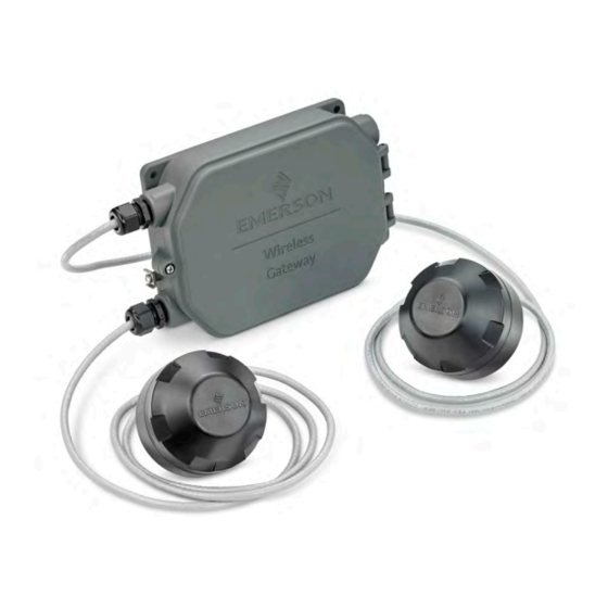
- Page 1 Reference Manual 00809-0600-4410, Rev AA September 2020 Emerson Wireless 1410S Gateway and 781S Smart Antenna...
- Page 2 The products described in this document are NOT designed for nuclear-qualified applications. Using non-nuclear qualified products in applications that require nuclear-qualified hardware or products may cause inaccurate readings. For information on Rosemount nuclear-qualified products, contact your local Emerson Sales Representative.
-
Page 3: Table Of Contents
3.1 Emerson Gateway 1410S2 installation overview................ 21 3.2 Power specifications........................21 3.3 Mounting the Emerson 1410S2 Gateway................... 22 3.4 Mounting the Emerson 781S Smart Antenna................24 3.5 Connecting the Emerson 1410S to the 781S Smart Antennas............ 25 3.6 Verify operations........................31 Chapter 4 Commissioning......................33 4.1 Overview........................... - Page 4 Redundant Gateway systems................... 53 B.1 Overview........................... 53 B.2 Requirements..........................53 B.3 Setup............................53 B.4 Diagnostics ..........................58 B.5 Gateway replacement........................59 Appendix C Dual mode network specifications................61 C.1 Dual mode upgrades......................... 61 C.2 IEC 62734 Network........................61 C.3 IEC 62734 Device support......................62 Emerson.com...
-
Page 5: Chapter 1 Introduction
September 2020 Introduction Emerson Wireless 1410S Gateway 781S Smart Antenna The Emerson Wireless 1410S Gateway and 781S Smart Antenna combine to create the ® main access point of a wireless network. Modbus communications over RS-485 or Ethernet provide universal integration and system interoperability. The optional OPC or ™... - Page 6 Introduction Reference Manual September 2020 00809-0600-4410 Emerson.com...
-
Page 7: Chapter 2 Configuration
Antenna positions The Emerson 781S Smart Antenna should be positioned vertically and be approximately 6 ft. (2 m) from large structures or buildings to allow for clear communication to other devices. If using two antennas, each should be mounted at least 3 ft. (0.91 m) from one another. - Page 8 Gateway are operationally equivalent and the following instructions are applicable to both. Powering the Gateway For the Emerson 1410S, bench top power will be needed to power the Gateway by wiring a 10.5–30 VDC (24 VDC if configured with I.S. barriers) power source. See Power...
- Page 9 Procedure 1. Click the Internet Access icon on the bottom right of the screen. 2. Select the Network and Sharing Center. 3. Select Local Area Connection. 4. Select Properties. 5. Select Internet Protocol Version 4 (TCP/IPv4) → Properties. Emerson 1410S/781S...
- Page 10 8. In the Subnet mask field, enter 255.255.255.0. 9. Select OK for both the Internet Protocol (TCP/IP) Properties window and the Local Area Connection Properties window. 2.3.3 Windows 10 Procedure 1. Select the network icon in the lower right corner. 2. Select the Network settings link. Emerson.com...
- Page 11 Reference Manual Configuration 00809-0600-4410 September 2020 3. Select Change adapter options. Emerson 1410S/781S...
- Page 12 If the PC/laptop is from another network, record the current IP address and other settings so the PC/laptop can be returned to the original network after the Gateway has been configured. 6. Select the Use the following IP address button. Emerson.com...
- Page 13 192.168.1.10 192.168.1.11 255.255.255.0 192.168.2.10 2.3.4 Disable proxies Use these steps to disable proxies. Procedure 1. Open web browser. 2. Navigate to Tools → Internet Options → Connections → LAN Settings (may be a different process for other browsers). Emerson 1410S/781S...
- Page 14 WirelessHART and ISA100 networks. Procedure 1. Access the WirelessHART default web page for the Gateway at https:// 192.168.1.10. You will have to configure both networks individually. a) Log on as Username: admin b) Type in password: default Emerson.com...
- Page 15 There are four role-based user accounts for the Gateway with varying levels of access. The access can be changed on the System Settings → Users → User Accounts by the admin user. The figure below displays this access. Emerson 1410S/781S...
- Page 16 It is suggested the default security settings in System Settings → Users → User Options be changed to the local IT best practices or the “Normal” setting after initial login. Strong or custom settings are available for more robust passwords. Emerson.com...
- Page 17 Network Time Protocol (NTP) is recommended for the best network performance because it always adjusts time to match the network time server. 2.3.9 To change the TCP/IP network settings Procedure 1. Navigate to System Settings → Gateway → Ethernet Communication. Emerson 1410S/781S...
- Page 18 4. Enter a save location and file name. 5. Select Save. 6. Select Return to form. Note System Backup contains user passwords and keys used for encrypting communication. Store downloaded system backups in a secure location. The actual files are also encrypted. Emerson.com...
- Page 19 1. Turn off power to the Gateway. 2. Locate the Reset switch. For the Emerson 1410S2 modular housing, the switch is located inside the Gateway housing cover on the DIP switch panel board. The reset switch is labeled switch 4.
- Page 20 Configuration Reference Manual September 2020 00809-0600-4410 Figure 2-3: DIP Switch Identification A. DIP switches B. PoE disabled C. Reset to defaults D. 1.5 kΩ pull-down resistor E. 120 Ω terminating resistor F. 1.5 kΩ pull-up resistor Emerson.com...
-
Page 21: Installing The Gateway
The Gateway should be mounted in a location that allows convenient access to the host system network (process control network). • Best practice is to install the Emerson 781S Smart Antennas centrally in the wireless network for the most direct connections to the Gateway. Physical description For dimensional drawing information refer to Appendix A. -
Page 22: Mounting The Emerson 1410S2 Gateway
Using an uninterruptible power supply (UPS) is recommended to ensure availability during power failure. NOTICE The Emerson 781S was designed for use with the Emerson 1410S Gateway and should only be connected to the Emerson 1410S and/or other Emerson Gateway products. Table 3-2: Emerson 781S Smart Antenna Power... - Page 23 The following hardware and tools are needed to mount the Gateway to a support bracket: Prerequisites • Four 15/16-in. bolts • Mounting support bracket • ⅜-in. drill ½ -in. socket-head wrench • Mount the Gateway using the following procedure: Emerson 1410S/781S...
-
Page 24: Mounting The Emerson 781S Smart Antenna
Figure 3-2: System Architecture Example Mounting location The Emerson Smart Antenna should be mounted in a location that allows convenient access to the host system network (wireless I/O) as well as the wireless field device network. Find a location where the Smart Antenna has optimal wireless performance. -
Page 25: Connecting The Emerson 1410S To The 781S Smart Antennas
There are two main connection configurations for the Emerson 1410S and 781S Smart Antennas: with and without intrinsically safe barriers. The hazardous location approval option of the Emerson 781S determines whether it needs to be installed with barriers. This connection is integrated in the Gateway electronics and can be selected upon order. - Page 26 Installing the Gateway Reference Manual September 2020 00809-0600-4410 provide intrinsic safety and approval for Emerson 781S installation in Div 1/Zone 0 areas. For more information on product approvals, see Reference data. The Gateway enclosure acts as a junction box for wiring connections. The enclosure has five conduit entries for power and communications wiring.
- Page 27 3.5.3 Emerson 781S installation A shielded twisted-pair cable is needed for connecting the Emerson 1410S and each 781S Smart Antennas. Each antenna can be located up to 1312 ft. (400m) from the Gateway. Figure 3-4: Emerson 1410S Gateway and Single 781S Smart Antenna A.
- Page 28 The switches number left to right going down from 5 to 1. The downward position on the switch is ON. Three DIP switches are provided to enable various terminating resistors to the RS-485 data bus. The terminating resistor on the Emerson 781S connection (120 ohm) is always enabled. Emerson.com...
- Page 29 These standards require the use of Category 5 Ethernet cable or higher. In the operation of IEEE 802.3a, PoE power is only transmitted from one device to another when the proper impedance match is made. This prevents damage to non PoE devices on the network. Emerson 1410S/781S...
- Page 30 For reference, Cisco offers the following four versions: 1. Pre standard PoE (Online Power) 2. 802.3af-compliant PoE (15W) 3. 802.3at-compliant PoE Plus (PoE+) (25W) 4. Universal PoE (UPoE) (60W). (New Cisco standard, which Cisco claims is compatible with IEEE 802.3af PoE and IEEE 802.3at PoE +) Emerson.com...
-
Page 31: Verify Operations
PoE FAQs What do I have to There is no specific option code for PoE. All 1410S Gateways have do to order IEEE PoE PoE. The only configuration needed is to flip DIP switch 5. Turning on a 1410S the switch “ON”... - Page 32 Join Key information. Once the field devices are powered, they will appear on the wireless network and communications can be verified under the Explore tab using the web interface. The time needed for the network to form will depend on the number of devices. Emerson.com...
-
Page 33: Commissioning
Commissioning Overview This section discusses the installation and setup of the optional software included with the Emerson Wireless Gateway. The following table describes what items are installed and on which disk they can be found. Table 4-1: Software Applications Name... -
Page 34: Software Installation
This is done by ® encrypting the standard data protocols (AMS Wireless Configurator, Modbus TCP, and OPC) used by the Gateway and making them available through various proxies within the Emerson.com... -
Page 35: Ams Wireless Configurator
® HART integrated operating environment that leverages the full capabilities of ® WirelessHART , including embedded data trending, charting, and graphical display capabilities provided by enhanced EDDL technology. • Display and modify device configuration • View device diagnostics Emerson 1410S/781S... -
Page 36: Licensing And Credits
Configurator. To display the release notes, navigate to Start → Programs → AMS Wireless Configurator → Help. Licensing and credits The latest licensing agreements are included on each disk of the software pack. This product includes software developed by the OpenSSL Project for use in the OpenSSL Toolkit. Emerson.com... -
Page 37: Operation And Maintenance
5-1) using a network switch, router, or hub. Often there are two networks for redundancy purposes. Figure 5-1: Ethernet Architecture A. Engineering station B. Primary control network C. Secondary control network D. Controller and I/O E. Wireless Gateway Emerson 1410S/781S... -
Page 38: Modbus
It is import that the Modbus communication settings in the Gateway match the settings in the Modbus master or client. Please refer to host system documentation for more information on how to configure these settings. The Modbus communication settings can be found by navigating to System Settings → Protocols → Modbus. Emerson.com... - Page 39 This setting determines parity (none, even, or odd) used for error checking purposes. This setting is only required for Modbus RTU. Stop Bits This setting determines the number (1 or 2) of stop bits used when ending a message. This setting is only required for Modbus RTU. Emerson 1410S/781S...
- Page 40 Use global scale gain This setting determines if a global gain and offset is applied for and offset? scaled integers or if each value has a unique gain and offset. Unique gain and offsets are found on the Modbus Mapping page. Emerson.com...
- Page 41 Global scale offset This value is added to the data values for the purpose of scaling integers. If global scaling is not selected, an offset value will be available for each separate data value on the Modbus Mapping page. Emerson 1410S/781S...
- Page 42 Operation and maintenance Reference Manual September 2020 00809-0600-4410 Emerson.com...
-
Page 43: Chapter 6 Troubleshooting
Troubleshooting 00809-0600-4410 September 2020 Troubleshooting Service support This section provides basic troubleshooting tips for the Emerson Smart Wireless Field Network. To receive technical support by phone: Global Service Center Software and Integration support United States-1 800 833 8314 International-63 2 702 1111... -
Page 44: Initial Connection: Cannot Find Gateway After Changing Ip Address
Possible cause: Incorrect credentials Recommended actions 1. Verify the user name and password (administrator user name is "admin", default password is "default"). 2. If unable to connect, consider resetting the Gateway. AMS Wireless Configurator: Gateway does not appear in AMS Wireless Configurator Emerson.com... -
Page 45: Ams Wireless Configurator: Wireless Devices Do Not Appear Under The Gateway
HART symbol Possible cause: Non-current device support files Recommended actions 1. Navigate to Emerson's AMS Device Manager product page. 2. Install latest device support files from AMS Wireless Configurator. AMS Wireless Configurator: Device configuration items are grayed out... -
Page 46: Wireless Field Devices: Wireless Device Does Not Appear On The Network
1. Verify the total number of devices on the network (25 maximum). 2. Go to SETUP → NETWORK → BANDWIDTH and click Analyze bandwidth. Any changes will require the network to reform. 3. Reduce the update rate for the device. Emerson.com... -
Page 47: Modbus Communications: Cannot Communicate Using Modbus ® Rtu
Navigate to SETUP → MODBUS → COMMUNICATIONS. 3. Verify Modbus register mapping in the Gateway. a) Log on to the Gateway. b) Navigate to SETUP → MODBUS → MAPPING. 6.15 Modbus communications: Cannot ® communicate using secure Modbus Emerson 1410S/781S... -
Page 48: Opc Communications: Opc Application Cannot Find A Gateway Opc Server
OPC communications: Gateway OPC server does not show any Gateways Possible cause: Proxy not configured Recommended actions Configure an OPC proxy for the Gateway (see Security setup utility). 6.18 OPC communications: Gateway OPC server does not show any data tags Emerson.com... -
Page 49: Ethernet/Ip ™ : Gateway Is Not Publishing The Parameters
To expedite the return process outside of North America, contact your Emerson representative. Within the United States, call the Emerson Response Center toll-free number 1 800 654 7768. The center, which is available 24 hours a day, will assist you with any needed information or materials. - Page 50 If the product being returned was exposed to a hazardous substance as defined by OSHA, a copy of the required Material Safety Data Sheet (MSDS) for each hazardous substance identified must be included with the returned goods. Emerson.com...
-
Page 51: Appendix A Reference Data
Reference data 00809-0600-4410 September 2020 Reference data Ordering information, specifications, and drawings To view current Emerson 1410S and 781S ordering information, specifications, and drawings, follow these steps: Procedure 1. Navigate to the product page for Emerson 1410S and 781S. 2. Scroll as needed to the green menu bar and click Documents & Drawings. - Page 52 Reference data Reference Manual September 2020 00809-0600-4410 Emerson.com...
-
Page 53: Appendix B Redundant Gateway Systems
Redundant Gateway systems Overview Redundancy for the Emerson Wireless 1410S Gateway increases the availability of the wireless field network by providing two sets of physical hardware which operate as a single Gateway system. This section covers setup and installation of a redundant Gateway system. - Page 54 4. Connect the secondary Ethernet port on Gateway A to the secondary Ethernet port on Gateway B (see Figure B-2). 5. After a few minutes, a dialog will appear on the page; select Form redundant pair. 6. Wait for the Pairing to redundant peer status to turn green. Emerson.com...
- Page 55 If significant configuration changes need to be downloaded to the standby Gateway, it may temporarily go offline shortly after the pair process is complete. This is expected behavior and does not represent instability in the system. Figure B-2: Redundant Pair Emerson 1410S/781S...
- Page 56 Mounting and connections Redundant Gateways follow similar mounting and connection practices as a standalone Gateway. Refer to Mounting the Emerson 1410S2 Gateway for more information. In addition to the standard practices, the following considerations should be taken when installing redundant Gateways.
- Page 57 The two Emerson 781S Smart Antennas should be mounted at the same height and be spaced between 3–9 ft. (1–3 m) horizontally. This is to ensure that they provide identical coverage for the wireless field network and to help eliminate coverage gap in the event of a switch over.
-
Page 58: Diagnostics
Gateway should be set to the active Gateway. To configure network connectivity check: 1. Navigate to System Settings → Gateway → Ethernet Communication. 2. Enter the host system IP address in the Check Network Connectivity IP Address field. 3. Select Save Changes. Emerson.com... -
Page 59: Gateway Replacement
Gateway. Navigate to System Settings → Gateway → Redundancy and follow the recommended actions on that page or follow the procedure above to pair Gateways and form a redundant system. Emerson 1410S/781S... - Page 60 Redundant Gateway systems Reference Manual September 2020 00809-0600-4410 Emerson.com...
-
Page 61: Appendix C Dual Mode Network Specifications
Dual mode network specifications Dual mode upgrades The Emerson Wireless 1410S Gateway has the ability to connect two Emerson 781S Smart Antennas. This upgrade can be added upon purchase of the Gateway, or it can be added later through an order option file. This option file can be downloaded through the Gateway web interface. -
Page 62: Iec 62734 Device Support
WirelessHART device does, this can show you whether or not the device is able to route information through it’s neighboring devices. If a device is considered a “router device” then it is communicating through it’s neighbors like a WirelessHART device. All published data from the device can also be viewed through this page. Emerson.com... - Page 63 Reference Manual Dual mode network specifications 00809-0600-4410 September 2020 Figure C-3: Detailed Device Information Page Emerson 1410S/781S...
- Page 64 Emerson Terms and Conditions of Sale are available upon request. The Emerson logo is a Facebook.com/Rosemount trademark and service mark of Emerson Electric Co. Rosemount is a mark of one of the Youtube.com/user/RosemountMeasurement Emerson family of companies. All other marks are the property of their respective owners.