Emerson Wireless 1410 Gateway Reference Manual
Hide thumbs
Also See for Wireless 1410 Gateway:
- Reference manual (76 pages) ,
- Quick start manual (20 pages) ,
- Reference manual (66 pages)

Related Manuals for Emerson Wireless 1410 Gateway


Summary of Contents for Emerson Wireless 1410 Gateway
- Page 1 Reference Manual 00809-0200-4410, Rev CA September 2020 Emerson Wireless 1410 Gateway...
- Page 2 The products described in this document are NOT designed for nuclear-qualified applications. Using non-nuclear qualified products in applications that require nuclear-qualified hardware or products may cause inaccurate readings. For information on Rosemount nuclear-qualified products, contact your local Emerson Sales Representative.
-
Page 3: Table Of Contents
6.6 AMS Wireless Configurator: Gateway does not appear in AMS Wireless Configurator....46 6.7 AMS Wireless Configurator: Wireless devices do not appear under the Gateway......47 ® 6.8 AMS Wireless Configurator: Wireless device appears with red HART symbol......47 6.9 AMS Wireless Configurator: Device configuration items are grayed out........47 Emerson.com/Rosemount... - Page 4 A.7 Ordering information........................ 62 A.8 Accessories and spare parts....................... 63 Appendix B Product Certifications....................65 B.1 European Directive Information....................65 B.2 Telecommunication Compliance....................65 B.3 FCC and IC..........................65 B.4 Ordinary Location Certification ....................65 B.5 Installing Equipment in North America..................65 Emerson.com/Rosemount...
-
Page 5: Chapter 1 Introduction
Introduction 00809-0200-4410 September 2020 Introduction Product overview ® The Emerson Smart Wireless Gateway 1410 (Gateway) connects WirelessHART self- ® organizing networks with host systems and data applications. Modbus communications over RS-485 or Ethernet provide universal integration and system interoperability. The ™... -
Page 6: Product Recycling/Disposal
Product Specifications and Product Certifications. Product recycling/disposal Recycling of equipment and packaging should be taken into consideration and disposed of in accordance with local and national legislation/regulations. Emerson.com/Rosemount... -
Page 7: Chapter 2 Configuration
Configuration Overview This section describes how to connect to Emerson Smart Wireless Gateway 1410 for the first time and the settings to configure before placing it on a live control network. It is important to note that some Gateways are used in stand-alone applications and do not reside on a network. - Page 8 Ethernet 1 port on the Gateway. Configure the gateway shows the standard terminal block diagram. Once the Gateway and PC/laptop are connected, wire a 24 VDC (nominal) power supply with a capacity of at least 250 mA to the Gateway power input terminals. Emerson.com/Rosemount...
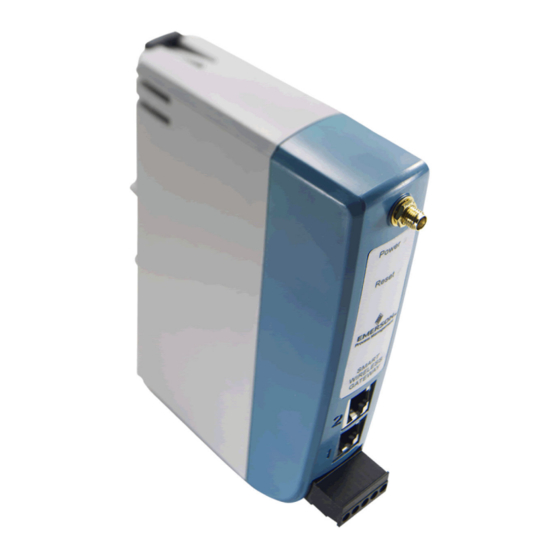
- Page 9 Reference Manual Configuration 00809-0200-4410 September 2020 Figure 2-1: Emerson Smart Wireless Gateway 1410 Housing Power Reset A DIN rail clip B SMA connector C Power and reset indicator lights: During normal operation the power indicator will be green. During a reset the reset light will turn red. The reset switch should not be enabled during normal operation.
- Page 10 Each of the initial passwords for the user accounts is default. It is recommended, for security purposes, that these passwords are changed. The administrator password should be appropriately noted when changed. If it is lost, do not return the Gateway to the factory, see Resetting to factory defaults. Emerson.com/Rosemount...
- Page 11 Antivirus Antivirus and other software tools are not included in the Gateway firmware. These software tools should be installed on any machine connected to the Gateway. Emerson bundles the latest software patches into our standard Gateway firmware updates. These software patches are not anti-malware or anti-virus tools in any sense of the word, but do provide the latest in security protection.
- Page 12 Network Time Protocol (NTP) is recommended for the best network performance because it always adjusts time to match the network time server. Failure to provide regular time synchronization over a long period of time (months) can cause the Gateway network to drift off time. Emerson.com/Rosemount...
- Page 13 Prior to the Gateway being installed and connected to a live control network, it should be configured with an IP address, as well as other TCP/IP network settings. This specific page can be found in System backup. Emerson.com/Rosemount...
- Page 14 Configuration Reference Manual September 2020 00809-0200-4410 Figure 2-3: Ethernet Settings Request the following configuration items from the network administrator: • Hostname • Domain Name • IP address • Netmask • Gateway Emerson.com/Rosemount...
- Page 15 1. Navigate to System Settings → Gateway → Backup and Restore → Save. 2. Select Save Configuration. 3. The Gateway collects the configuration date and when the file download pop up appears, select Save. 4. Enter a save location and file name. 5. Select Save. 6. Select Return to form. Emerson.com/Rosemount...
- Page 16 9. Verify the reset light is off, indicating the Reset switch is in the lower position. The Gateway will now be programmed back to factory defaults including IP addresses. The factory default IP addresses can be found in Table 2-1. Emerson.com/Rosemount...
-
Page 17: Chapter 3 Installation
September 2020 Installation Overview This section describes how to properly mount the Emerson Smart Wireless Gateway 1410 and make electrical connections, including electrical wiring, grounding, and host system connections. This section also describes how to mount the optional remote antenna. - Page 18 3. Place a flat or rounded object (such as a screw driver) into the DIN clip and apply a slight pressure downwards on the object. 4. Once the unit is released from the DIN rail pull backwards and down to successfully disengage. Figure 3-2: Removing Emerson.com/Rosemount...
-
Page 19: Remote Antenna
To maintain wireless performance and avoid non-compliance with spectrum regulations, do not change the length of cable or the antenna type. If the supplied remote mount antenna kit is not installed per these instructions, Emerson is not responsible for wireless performance or non-compliance with spectrum regulations. - Page 20 Any spare lengths of coaxial cable should be placed in 1-ft. (0,3 m) coils. Figure 3-3: Installation of WL2/WN2 Option A. User supplied enclosure containing Gateway B. Ground C. Remote antenna D. Cable E. Lightning arrestor F. Drip loop G. Earth Emerson.com/Rosemount...
-
Page 21: Connections
The secondary Ethernet port (Ethernet 2) can be used as a back up connection or a maintenance port for local access to the Gateway. Note Unless dual Ethernet ports were specified at the time of order, the secondary Ethernet port (Ethernet 2) will not be active. Emerson.com/Rosemount... - Page 22 Installation Reference Manual September 2020 00809-0200-4410 Figure 3-5: Emerson Smart Wireless Gateway 1410 Terminal Block Power Reset A+ B- 5-screw terminal block 24 VDC (nominal) power input ® Serial Modbus Ethernet connections should use Cat5e shielded cable to connect to an Ethernet hub, switch, or router.
- Page 23 Switch 2 is connected to a 120 ohm terminating resistor. This resistor is used to dampen signal reflections on long cable runs. RS-485 specifications indicate that the data bus Use a sharp non metal tool to switch between resistor options. Emerson.com/Rosemount...
- Page 24 250 mA of current. The positive and negative connections are depicted on the diagram shown in Figure 3-6. The wiring should include an external power shut-off switch or circuit breaker located near the Gateway. Note Using an uninterruptible power supply is recommended to ensure availability should there be a loss of power. Emerson.com/Rosemount...
-
Page 25: Chapter 4 Commissioning
This section discusses the installation and setup of the optional software included with the Emerson Smart Wireless Gateway 1410. This software is not required for the wireless field network to operate; however, it will aid in secure host integration as well as wireless field device configuration. -
Page 26: Software Installation
10. Installation will resume automatically after login. 11. Follow the prompts. Note If the autorun function is disabled on the PC, or installation does not begin automatically, double click D:\SETUP.EXE(where D is the CD/DVD drive on the PC) and select OK. Emerson.com/Rosemount... -
Page 27: Security Setup Utility
Users should be aware that with this flexibility comes certain risks. Opening the non- secure versions of an industrial protocol can expose significant information, some of it sensitive, about the wireless network. For this reason, Emerson encourages end users to use Emerson’s Security Setup Utility to secure the industrial protocols. Users running non- secure versions of the industrial protocols are encouraged to make sure the Gateway is running on a secure network and following security best practices. -
Page 28: Ams Wireless Configurator
During this process the Gateway will exchange security certificates (digital signatures) with the proxy. Figure 4-2: Security Setup Utility AMS Wireless Configurator AMS Wireless Configurator helps deploy and configure wireless field devices. It provides an ® integrated operating environment that leverages the full capabilities of WirelessHART Emerson.com/Rosemount... - Page 29 Step 6 if multiple Gateways need to be added. 8. Check the box to Enable Secure Communications with the Smart Wireless Gateway. 9. Select Finish to close the configuration window. 10. Select Close to exit the Network Configuration application. Emerson.com/Rosemount...
-
Page 30: Licensing And Credits
Licensing and credits The latest licensing agreements are included on each disk of the software pack. This product includes software developed by the OpenSSL Project for use in the OpenSSL Toolkit (http://www.openssl.org/). This product includes software written by Eric Young ([email protected]). Emerson.com/Rosemount... -
Page 31: Operation And Maintenance
September 2020 Operation and Maintenance Overview This section describes how to connect the Emerson Smart Wireless Gateway 1410 to a host system and integrate data gathered from the field device network. It covers network architectures, security, and data mapping. ®... - Page 32 An RS485 connection supports Modbus RTU protocol. Using this connection type, the Gateway is wired to an RS485 bus which typically leads to a serial I/O card or Modbus I/O card (see Figure 5-2). Up to 31 Gateways can be connected to a single I/O card in this manner. Emerson.com/Rosemount...
-
Page 33: Internal Firewall
TCP ports for communication protocols are user configurable, including user specified port numbers and the ability to disable ports. The Gateway’s internal firewall settings can be found by navigating to System Settings → Protocols → Protocols And Ports. Emerson.com/Rosemount... -
Page 34: Modbus
It is import that the Modbus communication settings in the Gateway match the settings in the Modbus master or client. Refer to host system documentation for more information on how to configure these settings. The Modbus communication settings can be found by navigating to System Settings → Protocols → Modbus. Emerson.com/Rosemount... - Page 35 Parity: This setting determines parity (none, even, or odd) to use for error checking purposes. This setting is only required for Modbus RTU. Stop Bits: This setting determines the number (1 or 2) of stop bits to use when ending a message. This setting is only required for Modbus RTU. Emerson.com/Rosemount...
- Page 36 Global scale gain: This value is multiplied to the data values for the purpose of scaling integers. If global scaling is not selected, a gain value will be available for each separate data value on the Modbus Mapping page. Emerson.com/Rosemount...
- Page 37 To add a new data point to the Modbus register map: Procedure 1. Select New entry. 2. Complete all of the table entries for the new data point (note that the entry columns may vary based on the Modbus communications settings). Emerson.com/Rosemount...
- Page 38 **_HEALTHY parameters are a true/false indication of the health of a particular variable (** = dynamic variable – PV, SV, etc…). These parameters incorporate critical diagnostics from the wireless field device as well as communication status. Emerson.com/Rosemount...
- Page 39 32-bit int Messages Sent Count 49010 32-bit int Valid Messages Ignored 49011 32-bit int Constant Float 12345.0 49012 32 float SYSTEM_DIAG.HART_DEVICES 49014 32-bit int SYSTEM_DIAG.ADDITIONAL_STATUS_0 49015 8-bit unsigned int SYSTEM_DIAG.ADDITIONAL_STATUS_1 49016 8-bit unsigned int SYSTEM_DIAG.ADDITIONAL_STATUS_2 49017 8-bit unsigned int Emerson.com/Rosemount...
-
Page 40: Ethernet/Ip
System Settings → Protocols → Ethernet/IP Note EtherNet/IP can be integrated with any approved EtherNet/IP ODVA member. Other ™ protocols such as HART-IP are still functional within the Gateway. Consult the Product Data Sheet (document number 00813-0200-4420) for ordering options. Emerson.com/Rosemount... - Page 41 EtherNet/IP member. Value reported for error Chooses what value is reported if the value’s associated status (floating point) indicates a critical failure. Only used if the Gateway is using float representation Emerson.com/Rosemount...
- Page 42 Register Mapping is the process of assigning data points from wireless field devices to EtherNet/IP registers. These registers can then be read by a EtherNet/IP master or client. EtherNet/IP register mapping can be found by navigating to System Settings → Protocols → Ethernet/IP. Emerson.com/Rosemount...
-
Page 43
<
> Navigates to the next page of this table Emerson.com/Rosemount... - Page 44 EtherNet/IP communications settings). 3. Repeat for each new data point. 4. Select Submit. 5. When changes have been accepted, select Return to form. Table 5-1 for options of parameters that can be mapped. Emerson.com/Rosemount...
-
Page 45: Chapter 6 Troubleshooting
Troubleshooting 00809-0200-4410 September 2020 Troubleshooting Service support This section provides basic troubleshooting tips for the Emerson Smart Wireless Field Network. To receive technical support by phone: Global Service Center Software and Integration support United States-1 800 833 8314 International-63 2 702 1111... -
Page 46: Initial Connection: Cannot Find Gateway After Changing Ip Address
Possible cause: Incorrect credentials Recommended actions 1. Verify the user name and password (administrator user name is "admin", default password is "default"). 2. If unable to connect, consider resetting the Gateway. AMS Wireless Configurator: Gateway does not appear in AMS Wireless Configurator Emerson.com/Rosemount... -
Page 47: Ams Wireless Configurator: Wireless Devices Do Not Appear Under The Gateway
HART symbol Possible cause: Non-current device support files Recommended actions 1. Navigate to Emerson's AMS Device Manager product page. 2. Install latest device support files from AMS Wireless Configurator. AMS Wireless Configurator: Device configuration items are grayed out... -
Page 48: Wireless Field Devices: Wireless Device Does Not Appear On The Network
1. Verify the total number of devices on the network (25 maximum). 2. Go to SETUP → NETWORK → BANDWIDTH and click Analyze bandwidth. Any changes will require the network to reform. 3. Reduce the update rate for the device. Emerson.com/Rosemount... -
Page 49: Modbus Communications: Cannot Communicate Using Modbus ® Rtu
Navigate to SETUP → MODBUS → COMMUNICATIONS. 3. Verify Modbus register mapping in the Gateway. a) Log on to the Gateway. b) Navigate to SETUP → MODBUS → MAPPING. 6.15 Modbus communications: Cannot ® communicate using secure Modbus Emerson.com/Rosemount... -
Page 50: Opc Communications: Opc Application Cannot Find A Gateway Opc Server
OPC communications: Gateway OPC server does not show any Gateways Possible cause: Proxy not configured Recommended actions Configure an OPC proxy for the Gateway (see Security setup utility). 6.18 OPC communications: Gateway OPC server does not show any data tags Emerson.com/Rosemount... -
Page 51: Ethernet/Ip ™ : Gateway Is Not Publishing The Parameters
To expedite the return process outside of North America, contact your Emerson representative. Within the United States, call the Emerson Response Center toll-free number 1 800 654 7768. The center, which is available 24 hours a day, will assist you with any needed information or materials. - Page 52 If the product being returned was exposed to a hazardous substance as defined by OSHA, a copy of the required Material Safety Data Sheet (MSDS) for each hazardous substance identified must be included with the returned goods. Emerson.com/Rosemount...
-
Page 53: Chapter 7 Glossary
00809-0200-4410 September 2020 Glossary This glossary defines terms used throughout this manual or those appearing in the Emerson Smart Wireless Gateway web interface. Term Definition Access Control A list of all devices that are approved to join the network. Each device will also List have a unique join key. - Page 54 WirelessHART field devices that are a part of the wireless field network. Device(s) Wireless Field WirelessHART network, consisting of Smart Wireless Gateway and multiple Network wireless field devices. Wireless Plant Industrial WiFi network, used to integrate the Wireless Field Network into the Network control network. Emerson.com/Rosemount...
-
Page 55: Appendix A Specifications And Reference Data
Meets all industrial environment requirements of EN61326 and NAMUR NE-21. Maximum deviation <1% span during EMC disturbance. During surge event, device may exceed maximum EMC deviation limit or reset; however, device will self-recover and return to normal operation within specified start-up time. Emerson.com/Rosemount... -
Page 56: Physical Specifications
Wiring: Single twisted shielded pair, 18 AWG. Wiring distance is approximately 4000-ft. (1,524 m) A.3.2 Ethernet 10/100base-TX Ethernet communication port ™ Protocols: Modbus TCP, OPC, EtherNet/IP, HART-IP , https (for Web Interface) Wiring: Cat5e shielded cable, Wiring distance 328-ft. (100 m) Emerson.com/Rosemount... -
Page 57: Self-Organizing Network Specifications
Assembly Input-Output instances are user configurable. EtherNet/IP specifications are managed and distributed by ODVA. For details on capabilities, see the Smart Wireless ® Gateway to Allen-Bradley Integration Manual (document number 00809-0500-4420) on Emerson.com/Rosemount.com. Self-organizing network specifications A.4.1 Protocol ® IEC 62591(WirelessHART ), 2.4 - 2.5 GHz DSSS. - Page 58 Inspects both incoming and outgoing packets. A.5.5 Third party certification Wurldtech: Achilles Level 1 certified for network resiliency National Institute of Standards and Technology (NIST): Advanced Encryption Standard (AES) Algorithm conforming to Federal Information Processing Standard Publication 197 (FIPS-197). Emerson.com/Rosemount...
-
Page 59: Dimensional Drawings
A RF connector on 1410 is an SMA female. Matching RF cable to antenna should be a SMA male. Note Allow extra space in front of unit for wiring, antenna connector and antenna cable service loop. Dimensions are in inches (millimeters). Emerson.com/Rosemount... - Page 60 Specifications and Reference Data Reference Manual September 2020 00809-0200-4410 Figure A-2: WX2 Basic Antenna Dimensions Dimensions are in millimeters. Emerson.com/Rosemount...
- Page 61 The remote omni-antenna kit includes sealant tape for remote antenna connection, SMA to N-type adapter cable, mounting brackets for the antenna, and lightning arrester. Antenna Lightning arrestor 50-ft. (15,2 m) cable 25-ft. (7,6 m) cable Figure A-4: SMA to N-Type Adapter Cable End cap Dimensions are in inches (millimeters). Emerson.com/Rosemount...
-
Page 62: Ordering Information
Single active 10/100 baseT Ethernet port with RJ45 connector. Additional ports disabled. Dual active 10/100 baseT Ethernet ports with RJ45 connectors. Multiple active ports have separate IP addresses, firewall isolation, and no packet forwarding. Convertible to RS232 via adapter, not included with Gateway. Emerson.com/Rosemount... -
Page 63: Accessories And Spare Parts
, High Gain, Remote antenna, 25-ft. (7.6 m) cable, and 01420-1615-0402 lightning arrestor Does not include SMA to N-type adapter. Can not upgrade from integral to remote antenna.Replacement Kits must be matched to original antenna type to maintain telecommunication approvals. I.e. WN2 cannot replace a WL2. Emerson.com/Rosemount... - Page 64 Specifications and Reference Data Reference Manual September 2020 00809-0200-4410 Emerson.com/Rosemount...
-
Page 65: Appendix B Product Certifications
RF spectrum. Nearly every country requires this type of product certification. Emerson is working with governmental agencies around the world to supply fully compliant products and remove the risk of violating country directives or laws governing wireless device usage. - Page 66 Equipment must be installed in a suitable tool accessible enclosure subject to the end use application. • Using the Emerson 1410D and the Smart Wireless Field Link 781 in a hazardous location requires barriers between the two units. B.5.3 Europe...
- Page 67 4. When fitted, the surface resistivity of the remote antenna is greater than 1 GΩ. To avoid electrostatic charge build-up, it must not be rubbed with a dry cloth or cleaned with solvents. Note Currently not available for Emerson 1410D option. Emerson.com/Rosemount...
- Page 68 Emerson Terms and Conditions of Sale are available upon request. The Emerson logo is a Facebook.com/Rosemount trademark and service mark of Emerson Electric Co. Rosemount is a mark of one of the Youtube.com/user/RosemountMeasurement Emerson family of companies. All other marks are the property of their respective owners.