
Related Manuals for Emerson 1410 A/B


Summary of Contents for Emerson 1410 A/B
- Page 1 Quick Start Guide 00825-0200-4410, Rev EA May 2018 ™ Emerson Wireless 1410 A/B and 1410D Gateway with 781 Field Link...
-
Page 2: Table Of Contents
May 2018 Quick Start Guide NOTICE This guide provides basic guidelines for the Emerson Wireless 1410 and 1410D Gateway. It does not provide instructions for diagnostics, maintenance, service, or troubleshooting. Refer to the Emerson Wireless Gateway 1410 Reference Manual for more information and instructions. The manuals and this guide are available electronically on Emerson.com/Rosemount. -
Page 3: Wireless Planning
Gateway Setup CD: 250 MB Initial connection and configuration To configure the Gateway, a local connection between a PC/Mac/laptop and the Gateway needs to be established. The Emerson 1410 and 1410D are operationally equivalent and the following instructions are applicable to both models. - Page 4 Quick Start Guide Powering the Gateway For both Emerson Wireless 1410A/B and the 1410D, bench top power will be needed to power the Gateway by wiring a 10.5–30 VDC (20–30 VDC if a 781 is connected with I.S. barriers to the Emerson 1410D) power source, with a capacity of at least 250 mA to the power terminals.
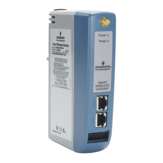
- Page 5 D. Ethernet port 1. When this port is activated, the factory IP address is 192.168.1.10. See Table 1 on page E. Emerson 1410 Power and Serial connections. Black terminal included in the box. F. Emerson Wireless 781 Field Link power and data connections. Black terminal included in box.
-
Page 6: Establishing A Connection
May 2018 Quick Start Guide Establishing a connection Connect the PC/laptop to the Ethernet 1 (Primary) receptacle on the Gateway using an Ethernet cable. Windows 7 1. Click the Internet Access icon on the bottom right of the screen. Figure 3. Internet Access 2. - Page 7 Quick Start Guide May 2018 5. Select Internet Protocol Version 4 (TCP/IPv4) then select Properties. Figure 5. Internet Protocol Version 4 (TCP/IPv4) Note If the PC/laptop is from another network, record the current IP address and other settings so the PC/laptop can be returned to the original network after the Gateway has been configured.
- Page 8 May 2018 Quick Start Guide 9. Select OK for both the Internet Protocol (TCP/IP) Properties window and the Local Area Connection Properties window. Windows 10 1. Select the network icon in the lower right corner. 2. Select the Network settings link. 3.
- Page 9 Quick Start Guide May 2018 4. Select Change adapter options. 5. See steps 4-10 from Windows 7 instructions. Note Connecting to the Gateway's secondary Ethernet port will require different network settings. Table 1. TCP/IP Network Settings Gateway PC/laptop/tablet Subnet Ethernet 1 192.168.1.10 192.168.1.12 255.255.255.0...
-
Page 10: Configure The Gateway
May 2018 Quick Start Guide Configure the Gateway To complete initial configuration for the Gateway: 1. Access the default web page for the Gateway at https://192.168.1.10 a. Log on as Username: admin b. Type in password: default 2. Navigate to System Settings > Gateway > Ethernet Communication to enter the Network Settings. -
Page 11: Physical Installation
Quick Start Guide May 2018 Physical installation Emerson 1410A/B and 1410D mounting The unit can be snapped onto a DIN TS35/7.5 or TS35/15 rail system. To clip the unit onto the DIN rail, see Figure 1. Tilt the unit at a slight angle allowing the lower lip of the chassis to catch the bottom of the DIN rail. - Page 12 Connecting the Emerson 1410D with 781 There are two main connection configurations for the Emerson 1410D and 781: with and without barriers. The location and hazardous approval option of the Emerson 781 determines whether it needs to be installed with barriers.
- Page 13 Quick Start Guide May 2018 Installation without barriers A shielded twisted pair cable is needed for connecting the Emerson 1410D and 781 (refer to Figure 9). The Emerson 781 can be located up to 656 ft. (200m) from the Emerson 1410D.
- Page 14 Quick Start Guide Installation with barriers When installing the Emerson 781 in a hazardous area there are two I.S. barriers that need to be installed: a power barrier and a signal barrier. The signal and the power are two separate I.S. circuits so they must comply with proper I.S.
- Page 15 Quick Start Guide May 2018 Figure 11. Emerson 1410D and 781 with Additional Power Supplied Barrier Installation 20-30 VDC Gray line means internal connection Data+ Data - 20-30 VDC Power Supply Safe Area Data - Data+ Hazardous Area Return (-)
- Page 16 Quick Start Guide Shield grounding The shield of the twisted pair cable needs to be grounded using the grounding terminal on the Emerson 1410D, and it should be taped back on the Emerson 781 side. Emerson 1410D Grounding The Emerson 1410D DIN rail cabinet must be grounded as well. A #6 AWG (4.11 mm European) copper wire bonding connector with the shortest length...
- Page 17 If the supplied remote mount antenna kit is not installed per these instructions, Emerson is not responsible for wireless performance or non-compliance with spectrum regulations.
- Page 18 May 2018 Quick Start Guide Installation of WL2/WN2 option 1. Mount the antenna on a 1 - to 2-in. pipe mast using the supplied mounting equipment. 2. Connect the lightning arrestor either to the electrical cabinet or directly outside the wall or right outside the wall (depending on where the Gateway is located).
- Page 19 Quick Start Guide May 2018 Figure 13. Installation of WL2/WN2 Option Indoor/outdoor cabinet and antenna Outdoor cabinet and antenna Outside Inside 300 mm (11.8-in.) minimum bend radius (May be polymer with grounding plate) Reference 300 mm (11.8-in.) ground minimum bend radius (when present) 300 mm (11.8-in.) minimum bend radius...
-
Page 20: Software Installation (Optional)
Gateway side. Insulate the shield to avoid grounding issues. ® In accordance with Emerson WirelessHART security guidelines (Emerson Wireless Security Whitepaper), the Gateway should be connected to the Host System via a LAN (Local Area Network) and not a WAN (Wide Area Network). -
Page 21: Verify Operations
If the autorun function is disabled on the PC, or installation does not begin automatically, double click D:\SETUP.EXE (where D is the CD/DVD drive on the PC) and select OK. For more information about the Security Setup Utility and AMS Wireless Configurator, see the Emerson Wireless Gateway 1410 Reference Manual. - Page 22 Explore tab using the web interface. The time needed for the network to form will depend on the number of devices. For more detailed installation instructions, see the Emerson Wireless Gateway 1410 Reference...
-
Page 23: Product Certification
Suitable for dry indoor locations only. Equipment must be installed in a suitable tool accessible enclosure subject to the end use application. Using the Emerson 1410D and the 781 Wireless Field Link in a hazardous location requires barriers between the two units... - Page 24 Equipment must be installed in a suitable tool accessible enclosure subject to the end use application. Using the Emerson 1410D and the 781 Wireless Field Link in a hazardous location requires barriers between the two units. Europe N1 ATEX Type n...
- Page 25 Note Currently not available for Emerson 1410D option. EAC - Belarus, Kazakhstan, Russia NM Technical Regulation Customs Union (EAC) Type n Certificate: TC RU C-US.Gb05.B.01111 Markings: 2Ex nA IIC T4 Gc X, T4(–40 °C ≤...
-
Page 26: Eu Declaration Of Conformity
May 2018 Quick Start Guide Figure 16. Emerson 1410 Wireless Gateway Declaration of Conformity EU Declaration of Conformity No: RMD 1093 Rev. F Rosemount, Inc. 8200 Market Boulevard Chanhassen, MN 55317-9685 declare under our sole responsibility that the product, Rosemount 1410 Wireless Gateway manufactured by, Rosemount, Inc. - Page 27 Quick Start Guide May 2018 EU Declaration of Conformity No: RMD 1093 Rev. F EMC Directive (2014/30/EU) Harmonized Standards: EN 61326-1: 2013 Radio Equipment Directive (RED) (2014/53/EU) Harmonized Standards: EN 300 328 V2.1.1 EN 301 489-17: V3.2.0 EN 60950-1: 2006+A11+A12+A1+A2 EN 50371: 2002 ATEX Directive (2014/34/EU) Baseefa14ATEX0125X –...
- Page 28 May 2018 Quick Start Guide EU Declaration of Conformity No: RMD 1093 Rev. F ATEX Notified Body SGS Baseefa Limited [Notified Body Number: 1180] Rockhead Business Park, Staden Lane Buxton, Derbyshire SK17 9RZ United Kingdom ATEX Notified Body for Quality Assurance SGS Baseefa Limited [Notified Body Number: 1180] Rockhead Business Park, Staden Lane Buxton, Derbyshire SK17 9RZ...
- Page 29 Quick Start Guide May 2018 China RoHS Rosemount 1410 List of Rosemount 1410 Parts with China RoHS Concentration above MCVs / Hazardous Substances Hexavalent Polybrominated Polybrominated Part Name Lead Mercury Cadmium Chromium biphenyls diphenyl ethers (Pb) (Hg) (Cd) (Cr +6) (PBB) (PBDE) Electronics...
- Page 30 Dubai, United Arab Emirates Electric Co. +971 4 8118100 Rosemount is a mark of one of the Emerson family of companies. All other marks are the property of their respective owners. +971 4 8865465 © 2018 Emerson. All rights reserved.