
Related Manuals for Emerson Copeland EazyCool OM 501 Series


Summary of Contents for Emerson Copeland EazyCool OM 501 Series
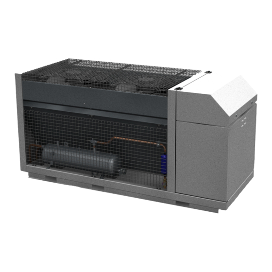
- Page 1 Application Guidelines Copeland Eazycool Large Outdoor ™ Condensing Units OM*-501 & OL*-501 OMTE-152D-TFD-501 & OLTE-82D-TFD-501...
-
Page 2: Table Of Contents
About these guidelines ....................1 Safety instructions ................... 1 1.1 Icon explanation ....................... 1 1.2 Safety statements ......................2 1.3 General instructions ......................2 Product description ..................3 2.1 Common information about Copeland OM(T)E & OL(T)E condensing units ....3 2.2 EU Ecodesign Directive 2009/125/EC ................ - Page 3 2.13.3 Location of the "Hot Key" plug connection on the XCM25D controller ....23 2.13.4 How to program a "Hot Key" from the controller (upload) ........23 2.13.5 How to program a controller using an Emerson "Hot Key" (download) ..... 23 2.14 Troubleshooting – Alarm history ..................24 2.15 Compressor motor protection ..................
- Page 4 4.2.2 Oil charging procedure ..................34 4.2.3 Oil separator ....................... 34 4.3 Rotation direction of Scroll compressors ............... 35 4.4 Maximum compressor cycle ..................35 4.5 Checks before starting & during operation ..............35 Maintenance & repair ..................36 5.1 Replacing a compressor ....................36 5.2 Condenser fins .......................
-
Page 6: About These Guidelines
Besides the support they provide, the instructions listed herein are also critical for the proper and safe functioning of the condensing units. Emerson will not guarantee the performance and reliability of the product if it is misused in regard of these guidelines. -
Page 7: Safety Statements
Safety statements Refrigerant compressors must be used in accordance with their intended use. Only qualified and authorized HVAC or refrigeration personnel are permitted to install, commission and maintain this equipment. Electrical connections must be made by qualified electrical personnel. ... -
Page 8: Product Description
Product description Common information about Copeland OM(T)E & OL(T)E condensing units Emerson has developed the Copeland large outdoor condensing unit of second generation to meet primarily the demands of the food retail and food service sectors. It is a refrigeration air- cooled condensing unit that uses the latest Copeland™... -
Page 9: Nomenclature
Nomenclature The model designation contains the following technical information about the condensing unit: Figure 2: Nomenclature OM & OL units Application range 2.6.1 Qualified refrigerants and oils R404A, R407A, R407F, R507, R448A, R449A Qualified refrigerants R134a*, R450A*, R513A* (* = Not for OL(T)E) Emkarate RL 32 3MAF Qualified servicing oils... -
Page 10: Application Limits
2.6.2 Application limits For application envelopes, please refer to the compressor application envelopes which can be found in Copeland™ brand products Select software, available at www.emersonclimate.eu. OM(T)E & OL(T)E condensing units can be used with an ambient temperature from -15°C to 45°C. For lower ambient temperatures please contact your local Application Engineering representative. -
Page 11: Figure 4: Main Components
Figure 4: Main components 2.7.2.1 Access inner part of condenser Side panel can be removed only when the unit is turned off. To remove the side panel unscrew 3 screws below condenser first continue to unscrew all remaining screws from outside then remove the cover by lifting Figure 5 : Open condenser segment C6.1.9/0617/E... -
Page 12: Compressor
2.7.3 Compressor Unit Digital Scroll Standard Scroll OMTE-152D-TFD-501 ZBD76K5E-TFD-567 ZB76K5E-TFD-567 OLTE-82D-TFD-501 ZFD41K5E-TFD-567 ZF41K5E-TFD-567 Table 4: Compressor model overview 2.7.3.1 Access compressor compartment The units allow easy access to all main components: Figure 6: Accessibility main components Opening of compressor chamber – unscrew two screws located on the top of compressor chamber cover and unplug green/yelow grounding cable by pulling and remove the cover by lifting Figure 7 : Open compressor compartment C6.1.9/0617/E... -
Page 13: Condenser Fan(S)
2.7.4 Condenser fan(s) The condensers of the OM(T)E & OL(T)E condensing units are equipped with electronically commutated (EC) external rotor motor with integrated EC controller Integrated motor contactor, active temperature management Interference emissions EN 61000-6-3 Interference immunity EN 61000-6-2 ... -
Page 14: Electrical Cabinet
2.7.5 Electrical cabinet Figure 9: Electrical cabinet 2.7.5.1 Access electrical cabinet For servicing & maintenance it’s necessary to open the unit housing at some time: Opening of electrical cabinet – release the lock located on both sides of electrical cabinet and open the cover up Figure 10 : Open electrical cabinet C6.1.9/0617/E... -
Page 15: P&I Diagram For Om(T)Q Units
2.7.6 P&I diagram for OM(T)Q units Figure 11: P&I diagram for OM(T)E units Position Description Comments PT P1 Pressure transmitter suction PPR15 TT SH Temperature Sensor suction inlet LP Mechanical Low Pressure switch PS1 (PSL) Emergency Mode TraxOil for active oil management 2 x OM30-N30 Tandem Set ZBD76 &... -
Page 16: P&I Diagram For Ol(T)Q Units
2.7.7 P&I diagram for OL(T)Q units IMPORTANT Absence of insulation on the liquid line in OL(T)E units! Air moisture condensation and lack of performance! Moisture will condensate on the liquid line and cause water droplets. The liquid line can pick up additional heat from the ambient which will adversely affect the sub-cooling desirable for the liquid refrigerant before it enters the expansion valve. -
Page 17: Xcm25D Electronic Controller - Features
XCM25D Electronic controller – Features The XCM25D controller is designed to be a powerful, flexible controller for use in multiple applications. It has been developed for condensing units and allows the adjustment of all relevant parameters by the user. 2.8.1 Description WARNING Electrical shock hazard! Serious personal injuries! There are unused fast- on pins (C1 &... -
Page 18: Main Control & Safety Features
Digital Scroll Condenser fan Liquid injection control control Superheat control EVI Monitoring of the discharge Electrical Alarm line temperature protection management Figure 14: XCM25D controller functionality overview 2.8.3 Main control & safety features Suction pressure control: Each unit is equipped with a suction pressure transmitter. The XCM25D controls the suction pressure by evaluating the input signal of the pressure transmitter. - Page 19 Fixed high-pressure switches: This is a non-adjustable protection device designed to prevent the compressor from operating outside of its safe high pressure range. Reset is automatic. OL(T)E & OM(T)E models: 28.8 bar cut-out / 24 bar cut-in. The high pressure cut out device is in the same safety chain like the discharge line thermostat.
-
Page 20: Emergency Mode
2.8.4 Emergency mode In case of controller malfunction, the unit provides an emergency operation mode. The controller will be completely by-passed and the system will continue to run based on low pressure switch (S7) cycling. The functionality of the high-pressure protection devices (S1 & S2) remain active for safety. -
Page 21: Heat Recovery Mode - Optional
-0.5 … 7 Upper setpoint [bar] (1) 0.5 … 5 Differential Setpoint (3) Lowest Setpoint [bar] -0.9 Factory Setting [bar] 3.5 / 4.5 Leakage Test pressure [bar] Connection port Solder 6mm 1. Upper Setpoint range spindle 2. Lower Setpoint 3. Differential spindle = variable •... -
Page 22: Xcm25D Electronic Controller - Programming
XCM25D Electronic controller – Programming CAUTION Low refrigerant charge! Compressor damage! Never energize the unit/controller without minimum refrigerant system charge. There is a risk of malfunction of the controller in deep vacuum operation which can cause compressor damage. 2.9.1 Programming the local display Figure 17: Local display Mode Function... -
Page 23: Remote Display Ccm60
There are two connection terminals on the back of the remote display (+ and -). NOTE: Emerson recommends to use a shielded cable twisted pair 2 x 0.5mm². The device must be connected to the VNR-terminal on the unit controller according to the polarity. -
Page 24: Single Commands
Before connecting cables make sure the power supply complies with the hardware requirements. Separate the terminal cables from the power supply cables, the outputs and the power connections. 2.9.3 Single commands Press the SET button to display the target setpoint. In programming mode, this allows to select a parameter or to confirm an operation. -
Page 25: Entering Programming Level 2 "Pr2
2.9.6 Entering programming level 2 "Pr2" To enter the Pr2 programming menu: Press simultaneously for 3 seconds. The first parameter label will be displayed. Press till the T18 label is displayed, then press the key; The blinking PaS label will be displayed; wait for a few seconds; ... -
Page 26: Controller Keyboard
2.10 Controller keyboard 2.10.1 How to lock the keyboard Keep the keys pressed simultaneously for more than 3 seconds. The "PoF" message will be displayed and the keyboard will be locked. At this point it is only possible to see the setpoint or the maximum or minimum temperatures stored. -
Page 27: Digital Operation
There is no way to reset the XCM25D controller to factory settings other than with additional equipment. Emerson recommends to use the Emerson "Hot Key" (not part of the standard delivery) to save the factory settings at initial power up. The same hot key can also be used to save user settings. -
Page 28: Applicable Hot Key For Om & Ol Units With Xcm25D Controller
2.13.2 Applicable hot key for OM & OL units with XCM25D controller The Emerson "Hot Key" DK00000300 can be used for uploading and downloading of parameter lists. Copeland ident number 3226456. Figure 21: Emerson "Hot Key" 2.13.3 Location of the "Hot Key" plug connection on the XCM25D controller The "Hot Key"... -
Page 29: Troubleshooting - Alarm History
2.14 Troubleshooting – Alarm history The controller records the total number of alarm activations (max 50) in the alarm menu (see Appendix 4). Action Key or display Notes Enter menu Push and release the ALR key. The menu to change the section will be entered. The Waiting for action alarm list section is active. -
Page 30: Compressor Motor Protection
(optional). 2.17.2 Ambient temperature sensor An ambient temperature sensor supplied by Emerson is connected to the electronic controller. This temperature sensor has several functionalities like emergency mode control, lower fan speed limitation and crankcase heater control. The sensor is located at the housing on the backside of the compressor compartment. -
Page 31: Installation
Installation WARNING High pressure! Injury to skin and eyes possible! Be careful when opening connections on a pressurized item. Copeland large outdoor OM(T)E &OL(T)E condensing units are delivered with a holding charge of neutral gas. The condensing unit should be in such a place to prevent any dirt, dust, plastic bag, leaves or papers from covering the condenser and its fins. -
Page 32: Condensing Unit Handling
Condensing unit handling 3.2.1 Transport and storage WARNING Risk of collapse! Personal injuries! Move refrigeration unit only with appropriate mechanical or handling equipment according to weight. Keep in the upright position. Don’t stack other pallets on top of the unit packaging. Keep the packaging dry at all times. -
Page 33: Weights
Figure 26: Center of gravity 3.2.2 Weights Outer Dimensions Gross Length / Width / Height Weight Weight [mm] (with closed cover) [kg] [kg] OMTE-152D-TFD-501 2303 / 900 / 1150 OLTE-82D-TFD-501 Table 16: Weights 3.2.3 Location & fixings IMPORTANT Dust and dirt contamination! Unit life reduction! The unit should always be installed in a location that ensures clean air flow. -
Page 34: Required Distances
3.2.4 Required distances Figure 27: Fixing dimensions and distances are in mm Refrigeration piping connections 3.3.1 Refrigeration piping installation WARNING High pressure! Risk of personal injury! The units are pressurized with dry air. Be careful when opening connections on a pressurized item. WARNING Low surface temperature! Danger of frostbite! The liquid line should be insulated with 19 mm insulation thickness. -
Page 35: Connection Sizes
Pipe runs should be kept as short as possible, using the minimum number of directional changes. Use large radius bends and avoid trapping of oil and refrigerant. This is particularly important for the suction line. The suction line should ideally slope gently towards the unit. Recommendation slope is 1/200 to 1/250. -
Page 36: Brazing Recommendations
3.3.3 Brazing recommendations IMPORTANT Blockage! Compressor breakdown! Maintain a flow of oxygen-free nitrogen through the system at very low pressure during brazing. Nitrogen displaces the air and prevents the formation of copper oxides in the system. If allowed to form, the copper oxide material can later be swept through the system and block screens such as those protecting capillary tubes, thermal expansion valves, and accumulator oil return holes. -
Page 37: Electrical Connection
Electrical connection 3.4.1 Power supply connections The electrical connection of the condensing unit to the power supply must be made by qualified technicians per the valid electrical directives, for instance DIN EN 60204-1. Also the voltage drop and temperatures on line must be considered for cable selection. Copeland large outdoor OM(T)E &... -
Page 38: Starting Up & Operation
Starting up & operation Before commissioning, ensure that all valves on the refrigeration unit are fully opened. Only qualified personal and certified company are allowed to do installation, commissioning, service & maintenance work. Evacuation CAUTION System pressure below atmospheric pressure! Compressor damage! Never energize the unit/controller without minimum refrigerant system charge. -
Page 39: Oil Charging Procedure
NOTE: The oil level in the oil separator sight glass should be always up to top end. Emerson recommends charging the oil with one of the following oil types: ... -
Page 40: Rotation Direction Of Scroll Compressors
Rotation direction of Scroll compressors Scroll compressors, like several other types of compressors, will only compress in one rotational direction. Three-phase compressors are protected against wrong rotation field by the unit controller. Maximum compressor cycle Maximum permitted starts per hour: 10. The factory setting of the XCM25D system controller already considers the maximum permitted starts and stops of the compressor and controls running time and minimal downtime. -
Page 41: Maintenance & Repair
Maintenance & repair Replacing a compressor CAUTION Inadequate lubrication! Bearing destruction! Exchange the accumulator after replacing a compressor with a burned-out motor. The accumulator oil return orifice or screen may be plugged with debris or may become plugged. This will result in starvation of oil to the new compressor and a second failure. In the case of a motor burnout, most contaminated oil will be removed with the compressor. -
Page 42: Routine Leak Testing
3. Emerson does not assume responsibility for the selection, use or maintenance of any product. Responsibility for proper selection, use and maintenance of any Emerson product remains solely with the purchaser or end user. -
Page 43: Appendix 1: Wiring Diagram (Status 08.06.2017) - Om(T)E / Ol(T)E Units (380-420V / 3Ph / 50 Hz)
08.06.2017) – OM(T)E / OL(T)E units (380-420V / 3Ph / 50 Hz) Appendix 1: Wiring diagram (Status Figure 32: Wiring Diagram page 1 C6.1.9/0617/E... - Page 44 Figure 33: Wiring Diagram page 2 C6.1.9/0617/E...
- Page 45 Figure 34: Wiring Diagram page 3 C6.1.9/0617/E...
-
Page 46: Figure 35: Wiring Diagram
Figure 35: Wiring Diagram page 4 C6.1.9/0617/E... -
Page 47: Figure 36: Wiring Diagram
Figure 36: Wiring Diagram page 5 C6.1.9/0617/E... -
Page 48: Figure 37: Wiring Diagram
Figure 37: Wiring Diagram page 6 C6.1.9/0617/E... -
Page 49: Figure 38: Wiring Diagram
Figure 38: Wiring Diagram page 7 C6.1.9/0617/E... -
Page 50: Figure 39: Wiring Diagram
Figure 39: Wiring Diagram Legend 1 C6.1.9/0617/E... -
Page 51: Figure 40: Wiring Diagram
Figure 40: Wiring Diagram page Legend 2 C6.1.9/0617/E... -
Page 52: Figure 41: Wiring Diagram
Figure 41: Wiring Diagram Legend 3 C6.1.9/0617/E... -
Page 53: Appendix 2: Parameter List Level 1 (Pr1)
Appendix 2: Parameter list level 1 (Pr1) Code Description Range R404A(0-404) - R507(1-507) - R134A(2-134) - R22(3-R22) - R407C(4-07C) - 8-R449A 8-R449A refrigerant Selection for Regulation R407A(5-07A) - R407F(6-07F) - R448A(48A) - R449A(8-49A) - R410A(9-410) Digital compressor set point C03 to C04 Proportional band for compressor regulation 0.1 to 9.9 bar;... -
Page 54: Appendix 3: Parameter List Level 1 & 2 (Pr1 & Pr2)
Appendix 3: Parameter list Level 1 & 2 (Pr1 & Pr2) MT Factory LT Factory Code Description Range Settings Settings 1-Suction pressure 1-Suction pressure Not used(0-NU) - Suction pressure (0-5V)(1- (0-5V) (0-5V) Probe P1 configuration SUP) 0-5V: -1.5 bar to A03; -21 PSI to A03; -150 KPA Start of scaling for probe 1 (0-5V) to A03 0-5V: A02 to 99.9 bar;... - Page 55 MT Factory LT Factory Code Description Range Settings Settings Probe P4 calibration -12°C to 12°C; -21°F to 21 °F Not used(0-NU) - Ambient Temp(NTC10K)(1- AMT) - Thermostat Temp(NTC10K)(2-TMT) - Vapor inlet Temp(NTC10K)(3-UIT) - Vapor outlet Temp(NTC10K)(4-UOT) - Evaporator Temp(NTC10K)(5-EPT) - Liquid Temp(NTC10K)(6-LLT)-Suction line Temp(7- SLT)-Coil Temp(8-COT) - Suction pressure switch(9-SUS) - Defrost thermostat input(10-...
- Page 56 MT Factory LT Factory Code Description Range Settings Settings Probe P7 calibration -12°C to 12°C; -21°F to 21 °F delay before activating probe error 0-255 sec 0-bar 0-bar Measurement unit for pressure bar(0-BAR) - PSI(1-PSI) - KPA(2-TPA) 0-°C 0-°C Measurement unit for temperature °C(0-C) - °F(1-F) P1(0-P1) - P2(1-P2) - P3(2-P3) - P4(3-P4) - P5(4-P5) - P6(5-P6) - P7(6-P7) - PEr(7-PER) -...
- Page 57 MT Factory LT Factory Code Description Range Settings Settings Cycle time for digital compressor 10 to 40 sec Safety value for PI regulator (in case of probe error) 0 to 100% Number of active compressor when probe error 0(0) - 1(1) - 2(2) Minimum capacity for digital compressor 0 to C25 Maximum capacity for digital compressor...
- Page 58 MT Factory LT Factory Code Description Range Settings Settings E35 to 99.9 Bar; E35 to 999 PSI; E35 to 999 High suction pressure point for condenser fan map 9(For R410A) Not Used(0-NU) - Envelope(1-Enu) - Floating 2-Floating HP 2-Floating HP Modulation fan setpoint calculation selection HP(2-FHP) 35.0...
- Page 59 MT Factory LT Factory Code Description Range Settings Settings 0-NO 0-NO Voltage and Current protection enabled no;yes H25=0: 0.0 to 70.0 A; 17.0 17.0 Maximum Continuous Current limit H25=1: 0.0 to 35.0 A. Voltage/Current sensing trip minimum off time 0 to 255 mim 15.4 15.4 Adjustable current limit before trip...
- Page 60 MT Factory LT Factory Code Description Range Settings Settings 0-oP 0-oP Digital input 2 polarity oP(0) - CL(1) Activation delay for digital input 2 0 to 255 min not used(0-NU) - Suction pressure switch(1- SUS) - Thermostat input(2-DEF) - High pressure input(3-HP) - Low pressure input(4-LP) - Door switch(5-DOR)-Energy saving Enable(6-ES)- 0-Not used...
- Page 61 MT Factory LT Factory Code Description Range Settings Settings Time for showing program name at startup 0 to 60 sec P1 visualization 0~999 P2 visualization 0~999 P3 visualization 0~999 P4 visualization 0~999 P5 visualization 0~999 P6 visualization 0~999 P7 visualization 0~999 Enter into PR2 level [0÷999]...
-
Page 62: Appendix 4: Alarm Menu
Appendix 4: Alarm menu Code Description Cause Action Reset AI1 error(Probe 1/Suction pressure Probe failure or out of Only in digital unit - compressor is Automatically as soon as the probe restarts transducer failure alarm) range activated according to C23, and working compressor on &... - Page 63 Code Description Cause Action Reset Lost phase error Power supply phase The compressor will be tripped Automatically: Lost phase recover and H08 loss(3 phases unit) delay time out Hold “start” button for 5s or manual power on Lost phase lockout Power supply phase The compressor will be locked loss happened for H12...
- Page 64 Code Description Cause Action Reset Hold “start” button for 5s or manual power on Open start circuit lockout Motor start winding The compressor will be locked(if H12 open error happened equal to 0, compressor no lockout) and off(if H12 equal to 0, compressor for H12 times within automatically start after H08 delay time out) one hour(single phase)
- Page 65 Code Description Cause Action Reset Low pressure alarm Only ON/OFF Warning signal only Suction pressure increase than parameter D29 configuration: suction or Cut out value pressure is lower than Cut out value and lower than parameter D29 for D12 time DGT compressor main configutaion: suction pressure is lower than...
- Page 66 Code Description Cause Action Reset Pump down alarm When liquid line Warning signal only Automatically solenoid is off, and time out MPd/G11 time is over after the time MPd/G11, compressor is still on High side flood back alarm The differential Warning signal only Automatically: as soon as differential temperature between...
- Page 67 Code Description Cause Action Reset Fan failure Fan alarm contact Warning signal only Verify fans protection open Max pressure alarm of superheating When the temperature See Paragraph The MOP control ends when the superheat is which converts from lower than the set point of superheating suction pressure rises above the set threshold (MoP/L08) for the time...
- Page 68 Code Description Cause Action Reset Probe configuration error Same probe Correct the wrong configuration Board need to be reset configuration present in Probe Configuration List (P3, P4, P5, P6, P7). For example, A13 = Ambient Temp(NTC10K), A15 = Ambient Temp(NTC10K); DI configuration error Same digital input Correct the wrong configuration...
-
Page 69: Appendix 5: Temperature / Resistance Curve For B7 Sensor (Customer Option)
Appendix 5: Temperature / resistance curve for B7 Sensor (customer option) R25 = 10kΩ B25/85=3435K Temp. Resistance Temp. Resistance Temp. Resistance Temp. Resistance Temp. Resistance Temp. Resistance [kΩ] [kΩ] [kΩ] [kΩ] [kΩ] [kΩ] [°C] [°C] [°C] [°C] [°C] [°C] 329.2 71.07 19.48 6.468... -
Page 70: Appendix 6: List Of Tables And Figures
Appendix 6: List of tables and figures Tables Table 1: Product range overview ..........................................3 Table 2: Qualified refrigerants and oils ........................................4 Table 3: Oil charge quantities ..........................................4 Table 4: Compressor model overview ........................................7 Table 5: Legend of the P&I diagram for OM(T)E units ..................................10 Table 6: Legend of the P&I diagram for OL(T)E units .................................. - Page 71 Figure 18: Remote display front panel mounting ....................................18 Figure 19: VNR connection for the remote display ....................................18 Figure 20: Digital operation ..........................................22 Figure 21: Emerson "Hot Key" ..........................................23 Figure 22: Location of "Hot Key" plug connection ....................................23 Figure 23: Outer dimensions ..........................................26 Figure 24: Transport and storage .........................................
- Page 72 Figure 44: Wiring Diagram Legend 3 ........................................47 C6.1.9/0617/E...
- Page 73 The Emerson logo is a trademark and service mark of Emerson Electric Co. Emerson Climate Technologies Inc. is a subsidiary of Emerson Electric Co. Copeland is a registered trademark and Copeland Scroll is a trademark of Emerson Climate Technologies Inc.. All other trademarks are property of their respective owners.