Table of Contents
Table of Contents

Related Manuals for Emerson Copeland Eazycool OMTE-90D-TFD


Summary of Contents for Emerson Copeland Eazycool OMTE-90D-TFD
- Page 1 Application Guidelines Copeland Eazycool ™ Large Outdoor Condensing Unit...
-
Page 2: Table Of Contents
About these guidelines ....................1 Safety instructions .................... 1 1.1 Icon explanation ......................... 1 1.2 Safety statements ......................1 1.3 General instructions ......................2 Product description ..................3 2.1 Common information about Copeland EazyCool™ Large Outdoor Condensing units ..3 2.2 EU Ecodesign Directive 2009/125/EC ................ - Page 3 2.16.3 Location of the "Hot Key" plug connection on the XCM25D controller ....22 2.16.4 How to program a "Hot Key" from the controller (upload) ........22 2.16.5 How to program a controller using an Emerson "Hot Key" (download) ....22 2.17 Troubleshooting – Alarm history ..................23 2.18 Compressor motor protection ..................
- Page 4 3.4 Location & fixings ......................30 3.5 Required distances ......................31 Starting up & operation................... 32 4.1 Evacuation ........................32 4.2 Charging procedure ......................32 4.2.1 Refrigerant charging procedure ................32 4.2.2 Charging level in liquid receiver ................33 4.2.3 Oil charging procedure ..................
-
Page 6: About These Guidelines
Besides the support they provide, the instructions listed herein are also critical for the proper and safe functioning of the condensing units. Emerson will not guarantee the performance and reliability of the product if it is misused in regard of these guidelines. -
Page 7: General Instructions
General instructions WARNING System breakdown! Personal injuries! Never install a system in the field and leave it unattended when it has no charge, a holding charge, or with the service valves closed without electrically locking out the system. System breakdown! Personal injuries! Only approved refrigerants and refrigeration oils must be used. -
Page 8: Product Description
Common information about Copeland EazyCool™ Large Outdoor Condensing units Emerson has developed the Copeland EazyCool™ Large Outdoor Condensing unit of second generation to meet primarily the demands of the food retail and food service sectors. It is a refrigeration air-cooled condensing unit that uses the latest Copeland™ brand products patented Scroll technology as the main driver and has electronic protection and diagnostics features built in the compact chassis. -
Page 9: Product Nameplate
Product nameplate The condensing unit nameplate shows model designation and serial number, as well as locked rotor amps, maximum operating current, safety pressures and weight. The compressor has its own nameplate with all electrical characteristics. Figure 2: Unit nameplate Nomenclature The model designation contains the following technical information about Copeland EazyCool Large Outdoor condensing units: Figure 3: Nomenclature OM &... -
Page 10: Application Range
For application envelopes, please refer to the compressor application envelopes which can be found in Copeland™ brand products Select software, available at www.climate.emerson.com/en-gb. OMTE & OLTE condensing units can be used at ambient temperatures down to -15°C. The application envelope of the unit must be respected under all operating conditions. -
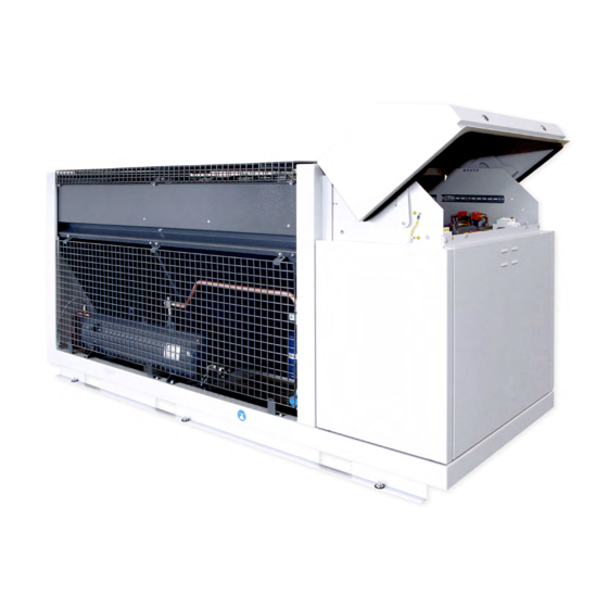
Page 11: Main Component Description
Main component description Figure 4: Main components of Large Outdoor Condensing units Bill of material 501 – General description 2.7.1 The standard bill of material for OMTE & OLTE units is 501. In general, these units have an air- cooled condenser with 1 or 2 EC-fans for condensing temperature control. A Tandem set of 2 Scroll compressors (ZB** for OMTE units, ZF** for OLTE units) provides the required cooling capacity. -
Page 12: Electrical Cabinet
2.7.4 Electrical cabinet Figure 5: Electrical cabinet 2.7.5 Condenser fan(s) The condensers of the OMTE & OLTE condensing units are equipped with electronically commutated (EC) external rotor motor with integrated EC controller: ▪ Integrated motor contactor, active temperature management ▪ Interference emissions EN 61000-6-3 ▪... -
Page 13: P&I Diagram For Omte-76D & Omte-90D Units
2.7.7 P&I diagram for OMTE-76D & OMTE-90D units Figure 7: P&I diagram for OMTE-76D & OMTE-90D Position Description Comments PT P1 Pressure transmitter suction (AI1) PPR15 Condensing pressure transmitter (AI2) PPR30 DLT Discharge line temperature sensor (AI3) NTC 86k Ambient temperature probe (AI6) NTC 10k Liquid receiver with liquid level watch LW4-L120 Alco... -
Page 14: P&I Diagram For Omte-152D Units
2.7.8 P&I diagram for OMTE-152D units Figure 8: P&I diagram for OMTE-152D Position Description Comments PT P1 Pressure transmitter suction (AI1) PPR15 Condensing pressure transmitter (AI2) PPR30 DLT Discharge line temperature sensor (AI3) NTC 86k Ambient temperature probe (AI6) NTC 10k Liquid receiver with liquid level watch LW4-L120 Alco PSL >>... -
Page 15: P&I Diagram For Olte-82D Units
2.7.9 P&I diagram for OLTE-82D units Figure 9: P&I diagram for OLTE units Position Description Comments PT P1 Pressure transmitter suction (AI1) PPR15 Condensing pressure transmitter (AI2) PPR30 DLT Discharge line temperature sensor (AI3) NTC 86k Ambient temperature probe (AI6) NTC 10k Liquid receiver with liquid level watch LW4-L120 Alco... -
Page 16: Xcm25D Electronic Controller - Features
XCM25D Electronic controller – Features The XCM25D controller is designed to be a powerful, flexible controller for use in multiple applications. It has been developed for condensing units and allows the adjustment of all relevant parameters by the user. 2.8.1 Description WARNING Electrical shock hazard! Serious personal injuries! There are unused fast-... -
Page 17: Main Control & Safety Features
Condenser fan Digital Scroll Liquid injection control control Superheat control Monitoring of the discharge Electrical Alarm line temperature protection management Figure 11: XCM25D controller functionality overview 2.8.3 Main control & safety features Suction pressure control: Each unit is equipped with a suction pressure transmitter. The XCM25D controls the suction pressure by evaluating the input signal of the pressure transmitter. -
Page 18: Xcm25D Electronic Controller - Programming
the discharge pipe of the digital compressor. The controller is using the signal from this sensor for control purposes as well as safety functions. Adjustable low-pressure alarm: The unit controller features an adjustable low-pressure alarm managed by the suction pressure sensor. The factory setting of this alarm is the lowest permitted pressure of the refrigerant with the lowest pressure-vapour properties. -
Page 19: Remote Display Ccm60
The remote display is a proprietary bus of communication for Dixell HMI (x-rep, CCM60) interfaces. There are two connection terminals on the back of the remote display (+ and -). NOTE: Emerson recommends using a shielded cable twisted pair 2 x 0.5mm². C6.1.9/0219/E... -
Page 20: Single Commands
The device must be connected to the VNR-terminal on the unit controller according to the polarity. Figure 14 shows the VNR terminal on the unit controller. VNR connection for the remote display Figure 14: VNR connection for the remote display Before connecting cables make sure the power supply complies with the hardware requirements. -
Page 21: Entering Programming Level 2 "Pr2
Confirm and Press the SET button: the value will blink for 3 seconds, then the store display will show the next parameter. Press simultaneously to exit the programming mode, or wait EXIT for 30 seconds (MTO) without pressing any key. Table 12: Programming level 1 parameters When entering the programming level for the first time the display will show the rtC (real time clock) label. -
Page 22: Controller Keyboard
2.10 Controller keyboard 2.10.1 How to lock the keyboard Keep the keys pressed simultaneously for more than 3 seconds. The "PoF" message will be displayed and the keyboard will be locked. At this point it is only possible to see the setpoint or the maximum or minimum temperatures stored. -
Page 23: Rescue Mode (Emergency Mode)
Figure 15: Digital operation NOTE: When the digital valve on the compressor is discharged the compressor is loaded. NOTE: At start-up the valve is energized for C20 start-up time, ie, time interval with the digital valve energized before regulation starts. It ranges from 0 to 10 seconds (factory setting = 5 seconds). -
Page 24: Ps1 - Setpoint Adjustment Low-Pressure Switch In Rescue Mode
Figure 16: Rescue mode – Control panel front view Figure 17: Rescue mode – Control panel bottom view Three LEDs (P1/P2/P3) show the status during rescue mode: ▪ P1 green = Cooling demand, compressors run according to S1 & S2 activation ▪... -
Page 25: Fan Operation In Rescue Mode
1. Upper setpoint range spindle 2. Lower setpoint 3. Differential spindle = variable ▪ PS1 pressure switches come with individually adjustable differential ▪ Use a flat screw driver or a ¼" refrigeration (square) wrench to adjust setpoints ▪ Adjust upper setpoint (1) using the range spindle (1) ▪... -
Page 26: Pumpdown - General
Application Engineering representative. 2.16.2 Applicable hot key for OM & OL units with XCM25D controller The Emerson "Hot Key" DK00000300 can be used for uploading and downloading of parameter lists. Copeland ident number 3226456. Figure 20: Emerson "Hot Key"... -
Page 27: Location Of The "Hot Key" Plug Connection On The Xcm25D Controller
NOTE: The "Err" message appears in case of a failed programming operation. In this case push the key again if you want to restart the upload or remove the "Hot Key" to abort the operation. 2.16.5 How to program a controller using an Emerson "Hot Key" (download) ▪ Turn the controller off. -
Page 28: Troubleshooting - Alarm History
2.17 Troubleshooting – Alarm history The controller records the total number of alarm activations (max 50) in the alarm menu (see Appendix 3). Action Key or display Notes Enter menu Push and release the ALR key. The menu to change the section will be entered. The Waiting for action alarm list section is active. -
Page 29: Compressor Motor Protection
2.20.2 Ambient temperature sensor An ambient temperature sensor supplied by Emerson is connected to the electronic controller. This temperature sensor has several functionalities like emergency mode control, lower fan speed limitation and crankcase heater control. -
Page 30: Installation
Installation WARNING High-pressure! Injury to skin and eyes possible! Be careful when opening connections on a pressurized item. The Large Outdoor OMTE & OLTE condensing units are delivered with a holding charge of neutral gas. The condensing unit should be located in such a place to prevent any dirt, dust, plastic bag, leaves or papers from covering the condenser and its fins. -
Page 31: Weights
Figure 24: Outer dimensions of OMTE-152E & OLTE-82D Outer dimensions Unit length/width/height with closed cover [mm] OMTE-76D-TFD 1574 / 920 / 1150 OMTE-90D-TFD OMTE-152D-TFD 2303 / 900 / 1150 OLTE-82D-TFD Table 17: Outer dimensions 3.1.3 Weights Net weight Gross weight Unit [kg] [kg]... -
Page 32: Lifting
3.1.4 Lifting WARNING Heavy equipment handling! Personal injuries! Never stay in the surrounding area when the unit is lifted. Use only adequate tools and fastening devices to secure the unit during transport and lifting. CAUTION Incorrect handling! Unit damage! Never use slings for transport or lifting as they would squeeze the unit. -
Page 33: Maximum Operating Currents For Cable Selection
3.2.2 Maximum operating currents for cable selection Max. Max. power consumption operating Single Single Unit Single fan current compressor heater [kW] [kW] [kW] OMTE-76D-TFD-501 5.53 0.66 OMTE-90D-TFD-501 6.26 0.66 OMTE-152D-TFD-501 22.4 0.66 0.66 OLTE-82D-TFD-501 20.5 0.66 0.66 Table 19: Maximum electrical values 3.2.3 Electrical wiring Before commissioning, ensure that the neutral "N"... -
Page 34: Connection Sizes
1/200 to 1/250. Upper and lower oil traps, double risers and reduced pipe diameters may be required for suction lines where long vertical risers cannot be avoided. All pipes should be adequately supported to prevent sagging which can create oil traps. The recommended pipe clamp support distance is shown in Table 20 below: Max distance between Tube size... -
Page 35: Brazing Procedure
Be sure tube fitting inner surface and tube outer surface are clean prior to assembly. ▪ Both tubes are extended from the condensing unit housing, therefore Emerson recommends isolating the housing by using a wet cloth on the copper tubing. -
Page 36: Required Distances
Where multiple units are to be installed in the same location, the contractor needs to consider each individual case carefully. There can be many variations of unit quantities and available space and it is not the intention of this manual to go over these. However, in general terms, air by-pass around each condenser and between the units should be avoided always. -
Page 37: Starting Up & Operation
Starting up & operation Before commissioning, ensure that all valves on the condensing unit are fully opened. Only qualified personal and certified companies are allowed to do installation, commissioning, service and maintenance work. Evacuation CAUTION System pressure below atmospheric pressure! Compressor damage! Never energize the unit/controller without minimum refrigerant system charge. -
Page 38: Charging Level In Liquid Receiver
Copeland Large Outdoor OMTE & OLTE condensing units are pre-charged with oil. After commissioning, the oil level should be checked and topped up if necessary. As mentioned in chapter 2.6.1 "Qualified refrigerants and oils", Emerson recommends charging with one of the following oil types: ▪... -
Page 39: Maximum Compressor Cycle
Maximum compressor cycle Maximum permitted starts per hour: 10. The factory setting of the XCM25D system controller already considers the maximum permitted starts and stops of the compressor and controls running time and minimal downtime. It is recommended to change these settings only in exceptional cases. Checks before starting &... -
Page 40: Maintenance & Repair
Maintenance & repair Opening the unit housing As part of standard servicing and maintenance it may be necessary to open the unit housing and covers. The unit allows easy access to all main components: 5.1.1 To open the electrical cabinet ▪... -
Page 41: To Access The Inner Parts Of The Condenser / Gas Cooler
5.1.4 To access the inner parts of the condenser / gas cooler ▪ The side panel can be removed only when the unit is turned off. ▪ To remove the side panel, unscrew the three screws located below the condenser first, then unscrew all the remaining screws and remove the cover by lifting it off. -
Page 42: Electrical Connections
As a rule, and for a clean environment, Emerson recommends that the fins be cleaned with liquid detergent diluted with clean water. The condensing unit has a well-designed chassis, and provided the unit is installed level, any cleaning solution should be able to drain away. A light brush downward (in the direction of the fins) should be done before washing to remove heavy deposits. -
Page 43: Disclaimer
3. Emerson does not assume responsibility for the selection, use or maintenance of any product. Responsibility for proper selection, use and maintenance of any Emerson product remains solely with the purchaser or end user. -
Page 44: Appendix 1: Parameter List Level 1 (Pr1)
Appendix 1: Parameter list level 1 (Pr1) Code Description Range R404A(0-404) - R507(1-507) - R134A(2-134) - R22(3-R22) - Refrigerant selection for R407C(4-07C) - R407A(5-07A) - R407F(6-07F) - 8-R449A 8-R449A regulation R448A(48A) - R449A(8-49A) - R410A(9-410) Digital compressor setpoint C03 to C04 Proportional band for 0.1 to 9.9 bar;... -
Page 45: Appendix 2: Alarm Menu
Appendix 2: Alarm menu Code Description Cause Action Reset Only in digital unit - Compressor is AI1 error (Probe 1/Suction pressure Probe failure or out of activated according to C23, and Automatically as soon as the probe restarts transducer failure alarm) range compressor on &... - Page 46 Code Description Cause Action Reset Power supply phase loss happened H12 Hold "start" button for 5 sec or manual power off Lost phase lockout The compressor will lock out times within one hour and on (3-phase unit) Incorrect phase Phase sequence lockout sequence (3-phase The compressor will lock out Manual power off and on...
- Page 47 Code Description Cause Action Reset Voltage lower than H13 Automatically as soon as voltage is back within Under voltage alarm The compressor will trip setting for H15 seconds acceptable range and H16 delay time-out Hold "start" button for 5 sec or manual power off Under voltage The compressor will lock out (if H17 and on (if H17 equal to 0, compressor starts...
- Page 48 Code Description Cause Action Reset Only ON/OFF configuration: suction pressure is lower than cut-out value and lower than parameter D29 for Suction pressure exceeds parameter D29 or Low-pressure alarm D12 time Warning signal only cut-out value Digital compressor main configuration: suction pressure is lower than D29 for D12 seconds...
- Page 49 Code Description Cause Action Reset When liquid line solenoid is off, and time out MPd/G11 time is Pumpdown alarm Warning signal only Automatically over after the time MPd/G11, compressor is still on The differential temperature between Automatically as soon as differential discharge and mid-coil High side floodback alarm Warning signal only...
- Page 50 Code Description Cause Action Reset Fan failure Fan alarm contact open Warning signal only Check fans protection When the temperature which converts from suction pressure rises The MOP control ends when the superheat is Max pressure alarm of superheating above the set threshold lower than the superheating setpoint (MoP/L08) for the time dMP/L10...
- Page 51 Code Description Cause Action Reset Same probe configuration present in Probe Configuration List (P3, P4, P5, P6, Probe configuration error P7). For example, Correct the configuration Board must be reset A13 = Ambient Temp (NTC10K), A15 = Ambient Temp (NTC10K) Same digital input configuration present in DI Input Configuration...
-
Page 52: Appendix 3: Temperature / Resistance Curve For B7 Sensor (Customer Option)
Appendix 3: Temperature / resistance curve for B7 Sensor (customer option) R25 = 10kΩ B25/85=3435K Temp. Resistance Temp. Resistance Temp. Resistance Temp. Resistance Temp. Resistance Temp. Resistance [kΩ] [kΩ] [kΩ] [kΩ] [kΩ] [kΩ] [°C] [°C] [°C] [°C] [°C] [°C] 329.2 71.07 19.48 6.468... -
Page 53: Appendix 4: List Of Tables And Figures
Appendix 4: List of tables and figures Tables Table 1: Product range overview ..........................................3 Table 2: Qualified refrigerants and oils ........................................5 Table 3: Oil charge in litres ............................................. 5 Table 4: Compressor model overview ........................................6 Table 5: Legend of the P&I diagram for OMTE-76D & OMTE-90D units ............................... 8 Table 6: Legend of the P&I diagram for OMTE-152D units.................................. - Page 54 Figure 18: Piping arrangement for heat recovery ....................................20 Figure 19: Heat recovery implementation......................................21 Figure 20: Emerson "Hot Key" ..........................................21 Figure 21: Location of "Hot Key" plug connection ....................................22 Figure 22: Maximum stacking loads for transport and storage ................................25 Figure 23: Outer dimensions of OMTE-76D &...
- Page 55 The Emerson logo is a trademark and service mark of Emerson Electric Co. Emerson Climate Technologies Inc. is a subsidiary of Emerson Electric Co. Copeland is a registered trademark and Copeland Scroll is a trademark of Emerson Climate Technologies Inc.. All other trademarks are property of their respective owners.