Quick Links

Related Manuals for Emerson COPELAND Stream Z9-4MA-22X


Summary of Contents for Emerson COPELAND Stream Z9-4MA-22X
- Page 1 ZX Condensing Unit Stream Condensing Unit User Manual User Manual...
-
Page 2: Table Of Contents
Table of Contents Page Introduction, Scope, Disclaimer Safety Information Nomenclature Features & Benefits CDU Layout Bill of Materials NextGen CoreSense Electrical Connections CDU Performance/Technical Data Installation & Start-up Commissioning Report... - Page 3 Scope of supply – Check page number 9 of this manual for detailed scope of supply. Disclaimer Thank you for purchasing the Emerson™ Stream Condensing Unit. We hope that this product meets your intended refrigeration requirement. Please read through this opera- tion manual to familiarize yourself with the installation, commissioning and operation of this product.
-
Page 4: Safety Information
Safety Information Installation and commissioning work on CDU shall be carried out only by qualified, refrigeration personnel who have been trained and instructed. Stream condensing unit is manufactured according to the latest safety standards. Emphasis has been placed on the user’s safety. For relevant standards please refer to the manufacturer’s declaration, available on request. - Page 5 1.5 General Instructions WARNING System breakdown! Personal injuries! Never install a system in the field and leave it unattended when it has no charge, a holding charge, or with the service valves closed without electrically locking out the system. System breakdown! Personal injuries! Only approved refrigerants and refrigeration oils must be used.
-
Page 6: Nomenclature
Nomenclature 4 M A 1 - 2 2 X - E W K - N Design X - POE Oil NextGen No. of Cylinders EW* Star/Delta CoreSense Revision AW* Part Winding M - StreaM Bore Motor Size Denomination 22 - 22 HP Displacement Features and Benefits Features... -
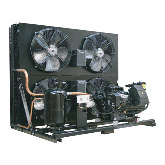
Page 7: Bill Of Materials
Condensing Unit Layout Item Description Service/Shut-off Valve Filter Drier (Optional) Liquid Receiver HP/LP Cut-out Base -frame Stream Compressor CoreSense Diagnostic Module Fans Condenser Junction Box Bill of Materials Nomenclature Option Standard Filter drier and hermetic moisture indicator fitted on the liquid line Filter drier, hermetic moisture indicator and oil separator fitted on the liquid line... - Page 8 Copeland Stream compressors is fitted with CoreSense module as a standard. Liquid Receiver Emerson CDUs are equipped with liquid receivers Rotalock service valve is provided at the receiver outlet Sight glass mounted on liquid receivers to help to not exceed maximum liquid level...
-
Page 9: Nextgen Coresense
Mounting Parts To minimize vibration and start/stop impulses flexible mounting should be used. Each Stream compressor is delivered with four colored mounting springs that are installed between the feet and the condensing unit base plate. These are clamped to avoid transport damage. - Page 10 Basic features Motor Overheat protection High discharge temperature protection Insufficient oil pressure protection Oil level protection (OM3) – Not used Current protection Phase failure protection Power consumption measurement Under/over voltage protection Crankcase heater control Part winding protection Switching frequency overstepping protection Connection with computer LEDs on terminal box cover Reset button for manual reset...
- Page 11 6.3 Motor overheat protection By using Positive Temperature Coefficient (PTC) thermistors on 4M* and 6M* Stream compressor models, Next Gen CoreSense provides motor overheating protection. Two chains of three thermistors each connected in series are embedded in the motor windings. Static overheat protection The Next Gen CoreSense module will trip the compressor if the motor windings are getting too hot.
- Page 12 6.5 Current Protection A current sensor is located in the terminal box. One power supply wire (2 from the same phase in case of part-winding) is going through this sensor. The direction of the leads has to be respected 6.6 Locked rotor protection If, 2.5 seconds after compressor start, the current is 150% of the MOC value, an alarm is triggered and the compressor trips.
- Page 13 At first start and at every power reset, the Next Gen CoreSense module automatically detects the compressor power supply (voltage and frequency) and will automatically select the corresponding MOC and undervoltage/overvoltage protection setpoints. If the measured voltage and/or frequency is different from the one defined on the nameplate, the module will generate a warning.
- Page 14 Voltage Imbalance Protection The purpose of this feature is to protect the compressor against a voltage imbalance that could lead to motor overheating. A configurable setting (default = 5 %) for voltage imbalance is used to determine the operating limit of the compressor. The voltage imbalance setting is configurable in the range of 2 to 8 % using the Next Gen CoreSense module app.
- Page 15 6.12 Compressor status codes Steady green: An indication of normal operation. There are no faults or issues with the compressor. Flashing green: An indication that there is a warning condition. The compres sor keeps running. Steady orange: An indication that the compressor is in emergency mode. Flashing orange: An indication that the compressor has tripped and will auto matically restart after a defined time (auto reset).
-
Page 16: Electrical Connections
6.14 Alarm history The 20 most recent alarms are stored in the module memory and can be downloaded with the Next Gen CoreSense module app. 6.15 Reset button Pressing the reset button is needed after a compressor lockout. In addition, it can be used for an immediate trip reset (no compressor waiting time to restart). - Page 17 Star / Delta motors can be connected direct-on-line or Star / Delta start Direct-on-line start Direct-on-line start Star / Delta start ∆ ∆ Star / Delta motor Y - ∆ Code E Compressor CoreSense/Control Wiring...
- Page 18 The Next Gen CoreSense module is originally delivered with basic modules pre-connected. *1-2 Power Supply, 19-20 Control circuit & 17-18 Welded contact alarm (optional) Part Winding Motors (AW...) Star/Delta Motors (EW...)
- Page 19 Z9 CDU: Fan Wiring Z12 CDU: Fan Wiring...
-
Page 20: Cdu Performance/Technical Data
CDU Performance/Technical Data a. 50 Hz Medium Temperature CDU Model Z9-4MA-22X Z9-4MH-25X Z9-4MI-30X Z9-4MJ-33X Z12-4MK-35X Z12-6MI-40X Comp Model 4MA-22X 4MH-25X 4MI-30X 4MJ-33X 4MK-35X 6MI-40X Capacity (kW) 26.6 30.2 32.8 35.3 41.9 Power Input (kW) 16.65 19.55 21.9 23.8 27.6 33.6 1.597597598 1.544757033 1.497716895... - Page 21 c. 60 Hz Medium Temperature CDU Model Z9-4MA-22X Z9-4MH-25X Z12-4MI-30X Z12-4MJ-33X Z12-4MK-35X Z12-6MI-40X Comp Model 4MA-22X 4MH-25X 4MI-30X 4MJ-33X 4MK-35X 6MI-40X Capacity (kW) 35.1 41.2 44.6 48.5 56.5 Power Input (kW) 19.75 23.2 27.5 29.8 33.8 41.2 1.57 1.51 1.50 1.50 1.43 1.37...
- Page 22 Emerson’s representative. The system is shipped with a holding charge of dry nitrogen. Check to see that pressure is still in the unit upon receipt. Report lack of pressure immediately to the Emerson’s application/sales representative. b. Installation Base The unit should always be installed in a location that ensures clean air flow.
- Page 23 d. Refrigeration Piping Installation All interconnecting pipes should be of refrigeration grade, clean, dehydrated and must remain capped at both ends until installation. Even during installation, if the system is left for any reasonable period (say two hours), pipes should be re- capped to prevent moisture and contaminants from entering the system.
- Page 24 f. Electrical All electrical work must be done in accordance with the National Electrical Code and existing local codes. Power supply must be the same as specified on the unit name plate. Voltage fluctuations in excess of 10 percent must be corrected. Breaker to be selected in accordance with specified limits, they must not be changed in size or shorted-out.
- Page 25 Leak Check The success of all the subsequent commissioning depends on a leak free system, free of contaminants, free of oxides, free of non-condensable’ s, that has been evacuated to a low vacuum and charged with the prescribed refrigerant. Leak test is particularly important for field-connected systems. Typically, field systems lose as much as 20%–30% of their refrigeration charge annually.
- Page 26 Charging and commissioning Step-by-step Ensure that there is no power supply to the unit. Hence, it is acceptable to leave the crankcase heater off. Connect the refrigerant cylinder to main service hose and purge line at the manifold end. Invert the refrigerant cylinder if necessary to ensure only liquid refrigerant can be charged into the system.
- Page 27 Remember that the refrigerant is under pressure. Always wear protective equipment, i.e. safety glasses or goggles and gloves when working with refrigerant, and guard against refrigerant spraying into the face or skin. Line pressures on an operating conditioning unit will vary with outdoor temperatures. As outdoor temperatures rise, pressures will also rise.
-
Page 28: 10. Commissioning Report
10. Commissioning Report A permanent data sheet should be prepared on each installation, with a copy for the owner and the original for the installing contractor. If another firm is to handle service and maintenance, additional copies should be prepared as necessary. System Reference Data The following information should be filled out and signed by the Refrigeration Installa- tion Contractor. - Page 29 About Emerson Emerson (NYSE: EMR), headquartered in St. Louis, Missouri (USA), is a global technology and engineering company providing innovative solutions for customers in industrial, commercial, and residential markets. Emerson Commercial and Residential Solutions business helps ensure human comfort and health, protect food quality and safety, advance energy efficiency, and create...