Emerson Copeland EazyCool ZX Series Application Manuallines
Outdoor condensing units for a2l applications
Hide thumbs
Also See for Copeland EazyCool ZX Series:
- Application manuallines (80 pages) ,
- Manual (26 pages) ,
- Application manuallines (71 pages)

Related Manuals for Emerson Copeland EazyCool ZX Series


Summary of Contents for Emerson Copeland EazyCool ZX Series
- Page 1 Application Guidelines Copeland EazyCool ™ Outdoor Condensing Units for A2L Applications ZX Range...
-
Page 2: Table Of Contents
About these guidelines ....................1 Safety instructions .................... 1 1.1 Icon explanation ......................... 1 1.2 Safety statements ......................1 1.3 General instructions ......................2 Product description ..................3 2.1 General information about Copeland™ EazyCool ZX condensing units ......3 2.2 EU Ecodesign Directive 2009/125/EC ................3 2.3 Main product features and dimensions ................ - Page 3 2.16.3 Location of the "Hot Key" plug connection on the XCM25D controller ....26 2.16.4 How to program a "Hot Key" from the controller (upload) ........26 2.16.5 How to program a controller using an Emerson "Hot Key" (download) ....27 2.17 Troubleshooting – Alarm history ..................27 2.18 Compressor motor protection ..................
- Page 4 Start-up & operation ..................37 4.1 Strength-pressure test ..................... 37 4.2 System tightness test ....................... 37 4.3 Evacuation ........................37 4.4 Charging procedure ......................38 4.4.1 Refrigerant charging procedure ................38 4.4.2 Oil charging procedure ..................39 4.4.3 Oil separator ......................39 4.5 Rotation direction of scroll compressors ................
-
Page 6: About These Guidelines
IMPORTANT: Only dedicated compressors and condensing units are allowed to be used with flammable refrigerants. Emerson marks all compressors and units that are qualified for flammable refrigerants with a sticker indicating the usage of such refrigerants. Systems using flammable refrigerants must be executed correctly while observing safety rules, as specified in corresponding safety standards such as, but not limited to EN 378. -
Page 7: General Instructions
compressor/refrigeration systems; non-trained personnel, including the user, are not allowed to do so and must call on an expert. ▪ The maximum refrigerant charge is specified in standards such as, but not limited to EN 378, EN 60335-2-40 and EN 60335-2-89. The system designer shall implement all safety measures defined by the applicable standards and the maximum refrigerant charge shall not be exceeded. -
Page 8: Product Description
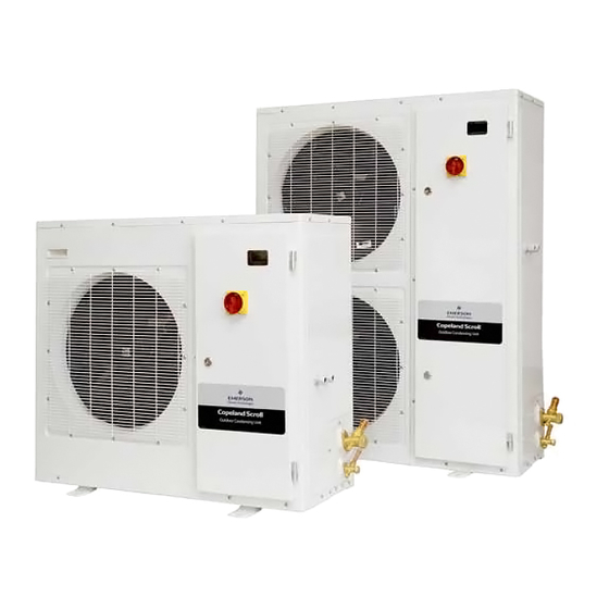
Product description General information about Copeland™ EazyCool ZX condensing units Emerson has developed the Copeland™ EazyCool ZX outdoor condensing unit of second generation to meet primarily the demands of the food retail and food service sectors. It is a refrigeration air- cooled condensing unit that uses the latest Copeland™... -
Page 9: Figure 1: Dimensions Of Models Zxmy-020E To Zxmy-040E And Zxdy-030E (Single-Fan Units)
Cooling Rated Displacement Refrigerant Nominal Unit @ 50 Hz capacity* current types power (kW) high side low side (kW) (bar) (bar) Medium temperature standard ZXMY-020E 3.42 1.58 ZXMY-030E 5.05 2.28 ZXMY-040E 11.7 6.58 3.29 10.8 R454A, R454C & R455A ZXMY-050E 14.4 8.77 3.79... -
Page 10: Product Nameplate
Figure 2: Dimensions of models ZXMY-050E to ZXMY-075E and ZXDY-040E to ZXDY-075E (dual-fan units) Product nameplate The condensing unit nameplate shows model designation and serial number, as well as locked rotor amps, maximum operating current, safety pressures and weight. The compressor has its own nameplate with all electrical characteristics. Nomenclature The model designation contains the following technical information about the condensing unit: Figure 3: Nomenclature ZX units... -
Page 11: Application Range
For application envelopes, please refer to the compressor application envelopes which can be found in Copeland™ brand products Select software, available at www.climate.emerson.com/en-gb. ZX condensing units can be used at ambient temperatures from -15 to 45 °C. For lower ambient temperatures please contact your local Application Engineering representative. -
Page 12: P&I Diagrams
P&I diagrams 2.8.1 ZXMY units Figure 4: P&I diagram for ZXMY units Fast access Position Description Comments menu High-efficiency Copeland scroll compressor Condenser with 1 or 2 fans Liquid receiver Filter drier / sight glass combination Expansion device for suction line injection Service valve, suction line Service valve, liquid line PSH (S1) -
Page 13: Zxdy Units
2.8.2 ZXDY units Figure 5: P&I diagram for ZXDY units Fast access Position Description Comments menu High-efficiency Copeland scroll compressor (YBD* for Digital) Oil separator Pre-charged with 0.5 L Condenser with 1 or 2 fans Liquid receiver Filter drier / sight glass combination Service valve, liquid line Service valve, suction line Crankcase heater... -
Page 14: Main Components Description
Main components description 2.9.1 Compressor Unit model Compressor model Medium temperature standard ZXMY-020E YB12K1E-TFMN ZXMY-030E YB17K1E-TFMN ZXMY-040E YB24K1E-TFMN ZXMY-050E YB31K1E-TFMN ZXMY-060E YB36K1E-TFMN ZXME-075E YB45K1E-TFMN Medium temperature Digital ZXDY-030E YBD17K1E-TFMN ZXDY-040E YBD24K1E-TFMN ZXDY-050E YBD31K1E-TFMN ZXDY-060E YBD36K1E-TFMN ZXDY-075E YBD45K1E-TFMN Table 7: Compressor models cross reference 2.9.2 Condenser fan(s) The condensers of the ZX condensing units are equipped with single-phase fans. -
Page 15: Xcm25D Electronic Controller - Features
2.10 XCM25D Electronic controller – Features The XCM25D controller is designed to be a powerful, flexible controller for use in multiple applications. It has been developed for condensing units and allows the adjustment of all relevant parameters by the user. 2.10.1 Description WARNING Electrical pins under voltage! Electrical shock hazard! There are unused... -
Page 16: Modbus Communication
The XCM25D controller can communicate via Modbus (RS-485) connection to provide all running data. Additional commands can also be activated through Modbus connection. The Modbus map is available on request from the Application Engineering department at Emerson. A pre-configured X-Web Supervisor device is also available and allows easy handling and connectivity with the XCM25D controller. -
Page 17: Additional Features For Customization
Automatic liquid injection on ZXMY: The electronic controller automatically instructs liquid refrigerant to be injected into the suction line of the scroll compressor to reduce discharge temperatures generated when the unit operates at increasing compression ratios. The electronic controller reacts automatically to a thermistor which is attached to the discharge line on all ZXMY units. -
Page 18: Figure 10: Pre-Arranged Additional Connections
Prearranged terminals / Component Description Wiring diagram Solenoid valve liquid line (not available on Terminals: X1.N / X1.8 ZXDY units) Room thermostat for pumpdown or direct Terminals: X1.9 / X1.10 control Sensor for evaporator or room Alarm contact Terminals: X1.11 / X1.12 Sensor for evaporator or room (NTC 10kΩ) Sensor B7 Terminals: X1.13 / X1.14... -
Page 19: Figure 11: External Temperature Sensor - Functionality
With these settings the controller will switch the compressor according to the status of the connected device (room thermostat): ▪ if the input is closed, turn the compressor on (On-Off-compressor) ▪ if the input is open, turn the compressor off (On-Off-compressor) Temperature control by means of an external temperature probe (not recommended for ZXDY units) The temperature of a cold room or cooling cabinet can be controlled by means of an additional... - Page 20 Adjustable discharge pressure limitation The controller has dedicated parameters to provide the possibility of adjustable discharge pressure cut-out. Recommended Parameter Description Factory settings settings Condenser temperature / Pressure Required value threshold for high alarm Condenser temperature / Pressure Required value threshold for alarm recovery Table 13: Discharge pressure limitations Low ambient operation...
- Page 21 Factory settings / Parameter Description Recommended settings / Comments Range Duration of pulse 15 minutes 0 to G19 defrost Defrost termination 10 °C -40 to +110 °C temperature Defrost delay time 15 minutes 0 to 255 minutes Defrost interval 0 = nu = Not used; 1 = in = Interval; G23** 0 = Not used = nu mode...
- Page 22 * G17 parameter >> Two defrost modes are available: ▪ G17 = EL → Defrost through electrical heater Compressor off ▪ G17 = pulse → Pulse / natural defrost Compressor off ** G23 parameter >> Defrost interval mode: ▪ G23 = nu (0) → Defrost functionality not used ▪...
-
Page 23: Xcm25D Electronic Controller - Programming
2.11 XCM25D Electronic controller – Programming CAUTION Low refrigerant charge! Compressor damage! Never energize the unit/controller without minimum refrigerant system charge. There is a risk of malfunction of the controller in deep vacuum operation which can cause compressor damage. 2.11.1 Programming the local display Figure 12: Local display Mode Function... -
Page 24: Remote Display Ccm60
There are two connection terminals on the back of the remote display (+ and -). NOTE: Emerson recommends using a shielded cable twisted pair 2 x 0.5 mm². The device must be connected to the VNR-terminal on the unit controller according to the polarity. -
Page 25: Double Commands - Entering Programming Level 1 "Pr1
2.11.4 Double commands – Entering programming level 1 "Pr1" Press simultaneously for about 3 seconds to lock (PoF) or unlock (Pon) the keyboard. Press simultaneously to leave the programming mode or menu. On submenus rtC and EEV this combination allows to go back to the previous level. Press simultaneously for about 3 seconds to access the first level of programming mode. -
Page 26: Fast Access Menu
2.11.7 Fast access menu This menu contains the list of probes and some values that are automatically evaluated by the board such as the superheat and the percentage of valve opening. "nP" or "noP" stands for "Probe not present" or "Value not evaluated", "Err" means "Value out of range"... -
Page 27: Parameters Level 1 - Required Settings
2.13 Parameters level 1 – Required settings The XCM25D is preconfigured to reduce the required settings on job-site to a minimum. In most cases, it will not be necessary to enter programming level 2 "Pr2". Table 21 gives an overview of the parameters available in programming level 1 "Pr1". -
Page 28: Pumpdown Mode
modulates the capacity according to the proportional band. If the pressure is lower than (C16-C17/2) the Digital compressor switches off. Figure 15: Digital operation NOTE: When the digital valve on the compressor is discharged the compressor is loaded. NOTE: At start-up the valve is energized for Sut/C20 start-up time, ie, time interval with the digital valve energized before regulation starts. -
Page 29: Pumpdown With Room Thermostat (Not Available With Zxdy Units)
Operation of the unit below the suction pressures shown in the table could result in tripping of the compressor internal motor protector (Klixon, error code E28). The envelopes are in accordance with Select software available at www.climate.emerson.com/en-gb. Unit family R1454A... -
Page 30: Internal Pumpdown With Temperature Sensor (Case Temperature)
2.15.4 Internal pumpdown with temperature sensor (case temperature) It is also possible to carry out pumpdown functionality in case a temperature sensor is used for temperature control (not part of the standard delivery). Parameters G56 and S07 have to be set up as described in Chapter 2.15.3 "Pumpdown with room thermostat (not available with ZXDY units)". -
Page 31: Reset To Factory Settings - Emerson "Hot Key
There is no way to reset the XCM25D controller to factory settings other than with additional equipment. Emerson recommends to use the Emerson "Hot Key" (not part of the standard delivery) to save the factory settings at initial power up. The same hot key can also be used to save user settings. -
Page 32: How To Program A Controller Using An Emerson "Hot Key" (Download)
2.16.5 How to program a controller using an Emerson "Hot Key" (download) ▪ Turn the controller off. ▪ Insert a pre-programmed "Hot Key" into the 5-pin receptacle and turn the controller on. ▪ The parameter list of the hot key will be automatically downloaded into the controller memory. -
Page 33: Compressor Motor Protection
2.18 Compressor motor protection The electronic controller protects the compressor motor against the following: ▪ overcurrent; ▪ phase loss; ▪ incorrect phase rotation; ▪ voltage imbalance. If the compressor motor current exceeds a predefined (non-adjustable) current limit, the electronic controller shuts the unit down and generates an error signal. For this function two of the main phase supply lines to the compressor (compressor via the contactor) are routed through the current sensors. -
Page 34: Installation
Installation WARNING High pressure! Injury to skin and eyes possible! Be careful when opening connections on a pressurized item. IMPORTANT The installation location must be selected in accordance with local workplace safety regulations. Copeland EazyCool ZX condensing units are delivered with a holding charge of neutral gas. The condensing unit should be located in such a place to prevent any dirt, dust, plastic bag, leaves or papers from covering the condenser and its fins. -
Page 35: Refrigeration Piping Connections
Refrigeration piping connections 3.2.1 Refrigeration piping installation WARNING High pressure! Risk of personal injury! The units are pressurized with dry air. Be careful when opening connections on a pressurized item. WARNING Low surface temperature! Danger of frostbite! The liquid line should be insulated with 19 mm insulation thickness. -
Page 36: Brazing Recommendations
3.2.2 Brazing recommendations WARNING Air/flammable refrigerant mixture! Creation of a potentially flammable atmosphere! Fire hazard! Remove all refrigerant before opening the system. When working on a refrigerant-filled system, make sure to follow the safety and working instructions given in Chapter 5 "Maintenance & repair". WARNING High temperature! Burning! Proceed with caution when brazing system components. -
Page 37: Brazing Procedure
3.2.3 Brazing procedure WARNING Air/A2L refrigerant mixture! Fire hazard! For systems using flammable A2L refrigerant, it is mandatory to flush oxygen-free nitrogen through the piping during the brazing process. Brazing must be carried out in compliance with ISO14903. Refer to Figure 21 and procedure below for the brazing of the stub tube connections of a scroll compressor: ▪... -
Page 38: Power Supply Connections
3.3.1 Power supply connections WARNING Electrical pins under voltage! Electrical shock hazard! There are unused fast-on pins (C1 & DO2) on the XCM25D which could be under voltage. They are covered by insulated fast-on flags in the factory. Handle carefully when removing insulating flags during service on site. -
Page 39: Low-Pressure Protection
Internal arcing! Motor destruction! Do not perform high-voltage or insulation tests if the compressor housing is under vacuum. Emerson subjects all units to a high-voltage test after final assembly. Each unit is tested according to EN 60034-1 at a differential voltage of 1000 V plus twice the nominal voltage. -
Page 40: Circuit Breaker With Overcurrent Protection
Special attention should be paid when performing a high-potential test and reading the Megohm resistance on A2L units, as such tests can induce an electrical arc and cause a fire hazard. For the same reason, compressors removed from a system with A2L refrigerant will need to have the oil drained and a nitrogen purge introduced to flush any remaining refrigerant from the compressor prior to high-potential testing and Megohm resistance reading. -
Page 41: Figure 23: Fixing Dimensions And Distances - Single-Fan Units
Figure 23: Fixing dimensions and distances – Single-fan units Figure 24: Fixing dimensions and distances – Dual-fan units Ideally, the unit should be mounted level on a solid concrete slab with anti-vibration pads between unit feet and concrete. However, the ZX condensing unit has also been designed for wall mounting on suitable brackets. -
Page 42: Start-Up & Operation
Start-up & operation WARNING Diesel effect! System explosion! The mixture of air and oil at high temperature can lead to an explosion. Avoid operating with air. WARNING Air/flammable refrigerant mixture! Creation of a flammable atmosphere! Make sure the atmosphere is non-flammable before starting the system. Ensure that the system contains only refrigerant and there is no flammable gas in the ambient. -
Page 43: Charging Procedure
should be evacuated down to an absolute pressure of 0.3 mbar. Proper evacuation reduces residual moisture to 50 ppm. During the initial procedure, suction and discharge shut-off valves on the compressor remain closed. The installation of adequately sized access valves at the furthest point from the compressor on the suction and liquid lines is advisable. -
Page 44: Oil Charging Procedure
NOTE: The oil level should be approximately halfway up the sight glass. As mentioned in chapter 2.6.1 "Qualified refrigerants and oils", Emerson recommends charging with one of the following oil types: ▪ Emkarate RL 32 3MAF ▪... -
Page 45: Pressure Fluctuations In Case Of Digital Unit
2.10.4 "Main control & safety featuresError! Reference source not found.". If this happens, immediately stop the unit and/or de-energize the power supply of the unit. Please also refer to the application envelopes which can be found in Select software, available at www.climate.emerson.com/en-gb. AGL_Unit_ZX_A2L_E_Rev00... -
Page 46: Maintenance & Repair
Maintenance & repair General considerations WARNING Conductor cables! Electrical shock! Follow the lockout/tag out procedure and the national regulations before undertaking any maintenance or service work on the system. Screwed electrical connections must be used in all applications. Refer to original equipment wiring diagrams. -
Page 47: Preparation And Work Procedure
Preparation and work procedure A work procedure shall be provided in the preparation stage. All maintenance staff and other personnel working at the site shall be instructed on the nature of the work being carried out. If any work is to be conducted on the refrigeration systems or any associated parts, appropriate fire extinguishing equipment shall be provided. -
Page 48: Replacing The Crankcase Heater
NOTE: Please refer to the Spare Parts list available at www.climate.emerson.com/en-gb/tools- resources to select the correct crankcase heater model. Caution: Crankcase heaters must be properly grounded! For the replacement of the crankcase heater, the manufacturer/installer shall follow the recommendations mentioned below. -
Page 49: Electrical Terminations
The presence of the heater shall be made evident by the posting of caution signs or markings at appropriate locations. Figure 27 Figure 28 Figure 29 Figure 30 Electrical connection ▪ Connect the crankcase heater according to the compressor application guidelines. ▪... -
Page 50: Condenser Fins
As a general guide it is advisable to do this at least once every two months. As a general rule and for a clean environment Emerson recommends that the fins be cleaned with liquid detergent diluted with clean water. The ZX unit has a well-designed chassis with levels sloping towards a large drainage hole and provided the unit is installed level, any cleaning solution should be able to drain away. -
Page 51: Disclaimer
3. Emerson does not assume responsibility for the selection, use or maintenance of any product. Responsibility for proper selection, use and maintenance of any Emerson product remains solely with the purchaser or end user. -
Page 52: Appendix 1: Overview Of The Zx Unit Components
Appendix 1: Overview of the ZX unit components Medium temperature Components Standard Digital ZXMY ZXDY Compressor M1 Fan M2.1 ZXMY-050E – ZXMY-075E ZXDY-050E – ZXDY-075E Fan M2.2 Y1 Stepper valve EVI Not used Not used Y1 Stepper valve liquid Y2 DGS solenoid valve E1 Crankcase heater S1 High-pressure switch S2 Low-pressure switch... -
Page 53: Appendix 2: Wiring Diagram - Zxmy Units (380-420 V / 3 Ph / 50 Hz)
Appendix 2: Wiring diagram – ZXMY units (380-420 V / 3 Ph / 50 Hz) Figure 32: Wiring diagram – ZXMY units AGL_Unit_ZX_A2L_E_Rev00... -
Page 54: Appendix 3: Wiring Diagram - Zxdy Units (380-420 V / 3 Ph / 50 Hz)
Appendix 3: Wiring diagram – ZXDY units (380-420 V / 3 Ph / 50 Hz) Figure 33: Wiring diagram – ZXDY units AGL_Unit_ZX_A2L_E_Rev00... -
Page 55: Appendix 4: Parameters Level 1
Appendix 4: Parameters level 1 Legend L1 = Parameter in level 1 (without password) L2 = Parameter in level 2 (with password = 3 2 1) N.V. = Parameter not accessible NOTE: When changing parameters C01 (Cin), C02 (CoU) and C05 (CPb) a reset of the controller (interruption of power supply) is required. Parameter Description Range... -
Page 56: Appendix 5: Alarm Menu
Appendix 5: Alarm menu Code Description Cause Action Reset Only in digital unit - compressor is AI1 error (Probe 1/Suction pressure Probe failure or out of activated according to C23, and Automatically as soon as the probe restarts transducer failure alarm) range compressor on &... - Page 57 Code Description Cause Action Reset Automatically: lost phase recovered and H08 Power supply phase delay time out. If all three phases are present Lost phase error The compressor will trip loss (3-phase unit) but the controller still shows the error message, set parameters H06 and H25 to "No".
- Page 58 Code Description Cause Action Reset Automatically: voltage is back within acceptable range and H16 delay time-out. If the voltage Voltage lower than H13 Under voltage alarm The compressor will trip corresponds to the required voltage but the setting for H15 seconds controller still shows the error message, set parameter H06 to "No".
- Page 59 Code Description Cause Action Reset Low-pressure switch Automatically: low-pressure switch closed and Low-pressure switch alarm The compressor will trip open D28 delay time-out. The pressure is below To deactivate the alarm function set parameter Low pressure alarm Warning signal only D13 to "No".
- Page 60 Code Description Cause Action Reset Min pressure alarm of superheating Not used High superheating alarm Not used Low superheating alarm Not used High room temperature alarm Not used Low room temperature alarm Not used Warning signal only if rrd/G09 is "no" If the door is open Manual or automatic –...
-
Page 61: Appendix 6: Additional Features For Customization
Appendix 6: Additional features for customization Required setting for proper functionality Setting needs to be adjusted according to application Room thermostat or pressure switch (not available on ZXDY units) – System restart is required! Parameter Parameter description Factory setting Required setting Compressor regulation probe selection SuP = Suction pressure probe dIS = Suction pressure switch / Room thermostat... - Page 62 Pumpdown with temperature sensor in case temperature (not available on ZXDY units) – System restart is required! Parameter Parameter description Factory setting Required setting Probe 7 configuration nu = Not used tnt = Thermostat temperature Compressor regulation probe selection SuP = Suction pressure probe CSt = Case temperature Case temperature probe selection nu = Not used...
- Page 63 Defrost with Real Time Clock – System restart is required! Parameter Parameter description Factory setting Required setting Probe 7 configuration nu = Not used EPt = Evaporator temperature Defrost probe selection nu = Not used EPt = Evaporator temperature Defrost interval mode nu = Not used rtC = Real time clock Relay output 2...
- Page 64 Evaporator fan – System restart is required! Parameter Parameter description Factory setting Required setting cn = Switch on and off with the compressor, stop during defrost On = Always on, stop during defrost Fans operating mode cy = Switch on and off with the compressor, run during defrost Oy = Always on, run during defrost Relay output 2...
-
Page 65: Appendix 7: Temperature / Resistance Curve For B7 Sensor (Customer Option)
Appendix 7: Temperature / resistance curve for B7 Sensor (customer option) R25 = 10 kΩ B25/85 = 3435 K Temp. Resistance Temp. Resistance Temp. Resistance Temp. Resistance Temp. Resistance Temp. Resistance (kΩ) (kΩ) (kΩ) (kΩ) (kΩ) (kΩ) (°C) (°C) (°C) (°C) (°C) (°C) -
Page 66: Appendix 8: List Of Tables And Figures
Appendix 8: List of tables and figures Tables Table 1: ZX condensing unit technical data ......................................4 Table 2: ZX condensing unit features ........................................4 Table 3: Qualified refrigerants and oils ........................................6 Table 4: BOM ................................................6 Table 5: Legend of the P&I diagram for ZXMY units ....................................7 Table 6: Legend of the P&I diagram for ZXDY units .................................... - Page 67 Figure 15: Digital operation ........................................... 23 Figure 16: Pumpdown functionality with temperature sensor ................................25 Figure 17: Emerson "Hot Key" ..........................................26 Figure 18: Location of "Hot Key" plug connection ....................................26 Figure 19: Maximum stacking loads for transport and storage ................................29 Figure 20: Brazing –...
- Page 68 The Emerson logo is a trademark and service mark of Emerson Electric Co. Emerson Climate Technologies Inc. is a subsidiary of Emerson Electric Co. Copeland is a registered trademark and Copeland Scroll is a trademark of Emerson Climate Technologies Inc.. All other trademarks are property of their respective owners.