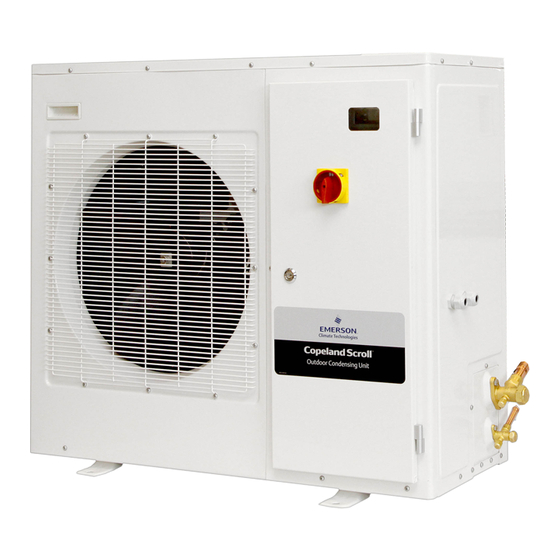
Emerson Copeland EazyCool ZX Series Manual
Outdoor
Hide thumbs
Also See for Copeland EazyCool ZX Series:
- Application manuallines (80 pages) ,
- Application manuallines (71 pages) ,
- Application manuallines (68 pages)
Table of Contents
Quick Links
Table of Contents

Related Manuals for Emerson Copeland EazyCool ZX Series


Summary of Contents for Emerson Copeland EazyCool ZX Series
- Page 1 Outdoor Condensing Units ZX Range...
-
Page 2: Table Of Contents
Safety instructions .................... 1 1.1 Icon explanation.........................1 1.2 Safety statements ......................1 1.3 General instructions ......................2 Product description ..................3 2.1 Common information about Copeland EazyCool™ ZX condensing units ......3 2.2 About this guideline......................3 2.3 Product range ........................3 2.4 Product nameplate......................3 2.5 Nomenclature........................3 2.6 Application range .......................4 2.6.1... - Page 3 3.2.2 Wiring diagram .....................13 3.2.3 Electrical protection standard (protection class) ..........15 3.3 Refrigeration connections ....................15 3.3.1 Refrigeration piping installation ................15 3.3.2 Brazing recommendations..................15 3.3.3 Brazing procedure ....................16 3.4 Location & fixings......................17 Starting up & operation................... 19 4.1 Evacuation ........................19 4.2 Charging procedure ......................19 4.2.1 Refrigerant charging procedure ................19 4.2.2...
-
Page 4: Safety Instructions
Safety instructions Copeland EazyCool™ ZX Outdoor Refrigeration Condensing Units are manufactured according to the latest European and US Safety Standards. Particular emphasis has been placed on the user's safety. These condensing units are intended for installation in machines and systems according to the EC Machines directive. -
Page 5: General Instructions
General instructions WARNING System breakdown! Personal injuries! Never install a system in the field and leave it unattended when it has no charge, a holding charge, or with the service valves closed without electrically locking out the system. System breakdown! Personal injuries! Only approved refrigerants and refrigeration oils must be used. -
Page 6: Product Description
This guideline is not intended to replace the system expertise available from system manufacturers. For additional information, please refer to the Product Catalogue or to the Copeland® Brand Products Selection Software accessible from the Emerson Climate Technologies website at www.emersonclimate.eu. Product range The application range is between –30°C and 7°C evaporating temperature. -
Page 7: Application Range
Application range 2.6.1 Qualified refrigerants and oils ZXME020E ZXME030E ZXME040E ZXME050E ZXME060E ZXME075E R404A/R507 Qualified refrigerant Emkarate RL 32 3MAF Qualified servicing oil Mobil EAL Artic 22 CC Oil charge ( litre ) 1.85 1.85 1.85 1.85 Table 1: Qualified refrigerants and oils 2.6.2 Application limits For application envelopes, please refer to the compressor application envelopes available in Copeland®... -
Page 8: Electronic Board Control And Operating Features
Electronic board control and operating features The function of the electronic board is to react to the On/Off signals received from devices such as thermostat to operate and protect the ZX unit. The electronic board control panel is fitted as standard and has been developed along with the compressor to provide the following control and protection systems: 2.8.1 Electronic board features... -
Page 9: Electronic Board Description
2.8.2 Electronic board description High/Low Pressure Switch Connectors Compressor Current Sensing (Hi/Lo) Setting Dip-Switch Compressor Type Setting Rotary-Switch 3-Phase Power Supply Input Temperature sensors 3-Phase Detect Module Switch Mode Diagnosis Module Power Supply Connector 1-Phase Power EXV Driver Supply Input Defrost Module Connector Evaporator Fan Mode Setting Dip-Switch... -
Page 10: Diagnostic Signal
2.8.3 Diagnostic signal Display LED 1 - Unit Status LED 2 - Error/Warning Code Idle (stops when reaches set- No error/warnings point) Compressor Phase Error (wrong phase sequence/loss of phase) About to start(*) Compressor Inside Thermal Protector Trip Defrost Compressor Over Current Stop due to error Discharge Gas Overheat Lockout... -
Page 11: Compressor / Unit Setting
Events LEDs Events LEDs When com- Unit Off / Phase “U” or “N” missing pressor On DLT Thermistors Failure When com- Power On W/O error pressor On PHE Vapour Inlet Temp. When com- Compressor On W/O error Sensor Failure (only ZXL) pressor On PHE Vapour Outlet Temp. -
Page 12: Compressor Motor Protection
2.10 Compressor motor protection The electronic board protects the compressor motor against the following: Over current Loss of any one phase Incorrect phase rotation If the compressor motor current exceeds a pre-defined current limit (non-adjustable), then the electronic board shuts down the unit and generates an error signal to the LED’s on the board. -
Page 13: Case Temperature Controller
Table 8: Electronic board 2C control reference guide 2.12.3 Condenser coil & ambient air thermistors These two thermistor type sensors are supplied by Emerson Climate Technologies and connected to the electronic board for condenser fan speed control. This is usually applicable where low ambient and (sometimes) low condensing temperatures are likely to adversely affect refrigeration performance and control. -
Page 14: Defrost Heater Contactor Coil (Not Supplied)
2.13.2 Defrost heater contactor coil (not supplied) An On/Off output connection is provided on the electronic board for direct connection of a customer-supplied contactor (coil) for convenience when the defrost option is included. Terminals are male spade type. Coil voltage rating should be 220VAC and current ratings 30VA (hold) and 330VA (inrush). - Page 15 Figure 4: Physical dimensions of ZXME050E, ZXME060E and ZXME075E (Dual-fan units) C6.1.6/1108-0509/E...
-
Page 16: Installation
Installation WARNING High pressure! Injury to skin and eyes possible! Be careful when opening connections on a pressurized item Copeland EazyCool™ ZX condensing units are delivered with a holding charge of neutral gas. The condensing unit should be located in such a place to prevent any dirt, plastic bag, leaves or papers from covering the condenser and its fins. - Page 17 C6.1.6/1108-0509/E...
-
Page 18: Electrical Protection Standard (Protection Class)
3.2.3 Electrical protection standard (protection class) Scroll compressors up to ZX51 are IP21 according to IEC 34. Fan IP44 according to IEC 34. Solenoid valve coils: IP65 according to DIN 43650. Refrigeration connections 3.3.1 Refrigeration piping installation IMPORTANT All interconnecting piping should be of refrigeration grade, clean, dehydrated and remain capped at both ends until installation. -
Page 19: Brazing Procedure
Remove the fishtails (= compressed tube ends) by cutting them off in the following sequence: 1. Remove the discharge connection fishtail 2. Then remove the suction connection fishtail Removing the plugs in this sequence prevents oil mist from coating the suction tube making brazing difficult. -
Page 20: Location & Fixings
Location & fixings IMPORTANT The unit should never be installed adjacent to a dust source. External fouling of the condenser fins also leads to high condensing temperatures, and will reduce the life of the unit. It is recommended that a clearance of 300 mm from the wall (or the next unit) be maintained from the unit left and rear panels whereas a clearance of 500 mm is to be maintained from the unit right, top and front panels (seen facing the front of the unit). - Page 21 are followed but additional consideration needs to be given for possible air recycling if units are stacked above and below each other. Wall mounting brackets are not included. Another factor to consider in finding a good installation site is the direction of the prevailing wind. For example if the air leaving the condenser faces the prevailing wind, the air flow through the condenser can be impeded, causing high condensing temperatures and ultimately resulting in reducing the life of the unit.
-
Page 22: Starting Up & Operation
Starting up & operation Before commissioning, ensure that all Rotalock valves and other valves on the condensing unit are fully opened. Evacuation NOTE: The following procedure is based upon achieving an actual system vacuum standard and is NOT TIME DEPENDENT! Step-by-step: ... -
Page 23: Oil Charging Procedure
NOTE: The oil level should be approximately halfway up the sight glass. Emerson Climate Technologies recommends charging the oil with one of the following oil types: Emkarate RL 32 3MAF ... -
Page 24: Maintenance & Repair
Maintenance & repair Replacing a compressor CAUTION Inadequate lubrication! Bearing destruction! Exchange the accumulator after replacing a compressor with a burned out motor. The accumulator oil return orifice or screen may be plugged with debris or may become plugged. This will result in starvation of oil to the new compressor and a second failure. -
Page 25: Electronic Panel
It is suggested that the main electromechanical terminations be checked for tightness at least once every 6 months. The components most likely to be affected by vibrations are the main terminal strip and compressor contactor. Most of the control wiring (and terminations) are low voltage connections and should not be affected in the same way as the heavier electro-mechanical terminations. - Page 26 Emerson Electric Co. Copeland is a registered trademark and Copeland Scroll is a tr ademark of Emerson Climate Technologies Inc.. All other trademark s are property of their respective owners. Information contained in this brochure is subject to change without noti cation.