Emerson Copeland EazyCool ZXME020E Application Manuallines
Outdoor condensing units
Hide thumbs
Also See for Copeland EazyCool ZXME020E:
- Manual (26 pages) ,
- Application manuallines (71 pages)
Table of Contents
Quick Links
- 1 Figure 1: Nomenclature Zx Units
- 2 Figure 4: P&I Diagram for Zxle Units
- 3 Figure 6: Electronic Controller
- 4 Figure 10: Local Display
- 5 Figure 13: Digital Operation
- 6 Figure 17: Dimensions of Models Zxme020E to Zxme040E, Zxde030E and Zxle020E to Zxle040E (Single-Fan Units)
- 7 Figure 25: Service Valves for Refrigerant Charging
- 8 Figure 27: Wiring Diagram - 3-Phase Motor
Table of Contents

Related Manuals for Emerson Copeland EazyCool ZXME020E


Summary of Contents for Emerson Copeland EazyCool ZXME020E
- Page 1 Application Guidelines Copeland EazyCool ™ Outdoor Condensing Units ZX Range...
- Page 2 About these guidelines ....................1 Safety instructions ................... 1 1.1 Icon explanation ....................... 1 1.2 Safety statements ......................1 1.3 General instructions ......................2 Product description ..................3 2.1 Common information about Copeland EazyCool™ ZX condensing units ....... 3 2.2 EU Ecodesign Directive 2009/125/EC ................3 2.3 Product range ........................
- Page 3 2.15.3 Location of the "Hot Key" plug connection on the XCM25D controller ....26 2.15.4 How to program a "Hot Key" from the controller (upload) ........26 2.15.5 How to program a controller using an Emerson "Hot Key" (download) ..... 27 2.16 Troubleshooting – Alarm history ..................27 2.17 Compressor motor protection ..................
- Page 4 4.1 Evacuation ........................36 4.2 Charging procedure ....................... 36 4.2.1 Refrigerant charging procedure ................. 36 4.2.2 Oil charging procedure ..................37 4.2.3 Oil separator ....................... 37 4.3 Rotation direction of Scroll compressors ............... 37 4.4 Maximum compressor cycle ..................38 4.5 Checks before starting &...
- Page 6 Besides the support they provide, the instructions listed herein are also critical for the proper and safe functioning of the condensing units. Emerson will not guarantee the performance and reliability of the product if it is misused in regard of these guidelines.
- Page 7 General instructions WARNING System breakdown! Personal injuries! Never install a system in the field and leave it unattended when it has no charge, a holding charge, or with the service valves closed without electrically locking out the system. System breakdown! Personal injuries! Only approved refrigerants and refrigeration oils must be used.
-
Page 8: Figure 1: Nomenclature Zx Units
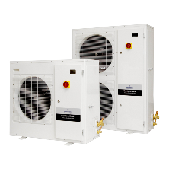
Product description Common information about Copeland EazyCool™ ZX condensing units Emerson has developed the Copeland EazyCool™ ZX outdoor condensing unit of second generation to meet primarily the demands of the food retail and food service sectors. It is a refrigeration air- cooled condensing unit that uses the latest Copeland™... - Page 9 Controller concept date separator accumulator ZXME 08/2008 Electronic main board ZXLE Electronic main board 07/2010 ZXDE EC2-552 (Emerson - Alco) ZXME 03/2013 Electronic main board ZXLE Electronic main board 03/2013 ZXDE XC645 (Emerson - Dixell) ZXME 01/2015 XCM25D (Emerson - Dixell)
- Page 10 Main component description 2.8.1 Compressor Medium temperature Low temperature Unit model Compressor model Unit model Compressor model Standard ZXME020E ZX15KCE-TFD/PFJ ZXLE020E ZXI06KCE-TFD/PFJ ZXME025E ZX19KCE-TFD/PFJ ZXLE025E ZXI08KCE-PFJ ZXME030E ZX21KCE-TFD/PFJ ZXLE030E ZXI09KCE-TFD/PFJ ZX29KCE-PFJ ZXME040E ZXLE040E ZXI14KCE-TFD or ZX30KCE-TFD ZXME050E ZX38KCE-TFD ZXLE050E ZXI15KCE-TFD ZXME060E ZX45KCE-TFD ZXLE060E...
-
Page 11: Figure 2: Zx Unit Housing
Figure 2: ZX unit housing C6.1.6/0117-1017/E... -
Page 12: Figure 3: P&I Diagram For Zxme Units
2.8.4 P&I diagram for ZXME units Figure 3: P&I diagram for ZXME units Fast access Position Description Comments menu 1 (M1) High efficient Copeland Scroll compressor 2 (M2) Condenser with 1 or 2 fans Liquid receiver with service valve Filter drier / sight glass combination 5 (Y1) Expansion device for suction line injection Service valve, suction line... -
Page 13: Figure 4: P&I Diagram For Zxle Units
2.8.5 P&I diagram for ZXLE units IMPORTANT Absence of insulation on the liquid line in ZXLE units! Air moisture condensation and lack of performance! Moisture will condensate on the liquid line and cause water droplets. The liquid line can pick up additional heat from the ambient which will adversely affect the sub-cooling desirable for the liquid refrigerant before it enters the expansion valve. -
Page 14: Figure 5: P&I Diagram For Zxde Units
2.8.6 P&I diagram for ZXDE units IMPORTANT Check valve in front of liquid receiver! Risk of excessive internal pressure caused by liquid expansion! Check necessary safety devices according to EN 378. Figure 5: P&I diagram for ZXDE units Fast access Position Description Comments... -
Page 15: Figure 6: Electronic Controller
XCM25D Electronic controller – Features The XCM25D controller is designed to be a powerful, flexible controller for use in multiple applications. It has been developed for condensing units and allows the adjustment of all relevant parameters by the user. 2.9.1 Description WARNING Electrical shock hazard! Serious personal injuries! There are unused fast- on pins (C1 &... -
Page 16: Figure 7: Xcm25D Controller Functionality Overview
Condenser fan Digital Scroll Liquid injection control control (ZXDE) (ZXME) Superheat control EVI (ZXLE) Monitoring of the discharge Electrical Alarm line temperature protection management Figure 7: XCM25D controller functionality overview 2.9.3 Main control & safety features Suction pressure control: Each unit is equipped with a suction pressure transmitter. The XCM25D controls the suction pressure by evaluating the input signal of the pressure transmitter. - Page 17 ▪ ZXLE & ZXME units: 28 bar cut-out / 21 bar cut-in. ▪ ZXDE units: 28.8 bar cut-out / 24 bar cut-in. Adjustable high pressure limitation: The unit controller provides the possibility to stop the unit at a required discharge pressure which is lower than the cut-out value of the fixed high-pressure switch. Detailed instructions can be found in chapter 2.9.4 "Additional features for customization"...
-
Page 18: Figure 8: Prearranged Additional Connections
Prearranged terminals / Component Description Wiring diagram Low pressure switch, optional; can be Terminals: X1.2 / X1.7 ordered factory-installed. Solenoid valve liquid line (not available on Terminals: X1.N / X1.8 ZXDE units) Room thermostat for pump-down or direct Terminals: X1.9 / X1.10 control Alarm contact Sensor for evaporator or room... -
Page 19: Figure 9: External Temperature Sensor - Functionality
Factory settings / Recommended settings / Parameter Description Range Comments Compressor 1 = Suction pressure Suction pressure switch / Room regulation probe probe = SuP thermostat input = 3 = diS selection NO >> If a solenoid is used in the Use the liquid line liquid line, see Chapter 2.13 "Pump-down - General"... - Page 20 Factory settings / Parameter Description Recommended settings / Comments Range Case temperature Define limits to avoid wrong operator -10°C / -40°C to G05 lower limit G02 settings for G02 Case temperature Define limits to avoid wrong operator +15°C / G04 to 110°C upper limit G02 settings for G02 Emergency run...
- Page 21 Factory settings / Parameter Description Recommended settings / Comments Range Probe 7 0 = Not used = nu Evaporator temp (NTC10K) = 5 = EPt configuration Defrost probe 0 = Not used = nu 5 = Evaporator temperature sensor = EPt selection 0 = Electrical = EL;...
- Page 22 Factory settings / Parameter Description Recommended settings / Comments Range 0 = SUN; 1 = MON; 2 = TUE; 3 = WED; First weekly SUN = Sunday 4 = THU; 5 = FRI; 6 = SAT; holiday 7 = nu = Not used 0 = SUN;...
-
Page 23: Figure 10: Local Display
2.10.1 Programming the local display Figure 10: Local display Mode Function Compressor 1 enabled Flashing Anti-short cycle delay enabled Condensing fans enabled Bar display Flashing Programming mode PSI display Flashing Programming mode When browsing the service menu Flashing In fast access menu When browsing the alarm menu Flashing A new alarm occurred... -
Page 24: Figure 11: Remote Display Front Panel Mounting
There are two connection terminals on the back of the remote display (+ and -). NOTE: Emerson recommends to use a shielded cable twisted pair 2 x 0.5mm². The device must be connected to the VNR-terminal on the unit controller according to the polarity. - Page 25 2.10.3 Single commands Press the SET button to display the target setpoint. In programming mode, this allows to select a parameter or to confirm an operation. Press the RESET button and hold for 5 seconds to reset any lockouts if the current state of the controller allows for it to be reset.
- Page 26 2.10.6 Entering programming level 2 "Pr2" To enter the Pr2 programming menu: ▪ Press simultaneously for 3 seconds. The first parameter label will be displayed. ▪ Press till the T18 label is displayed, then press the key; ▪ The blinking PaS label will be displayed; wait for a few seconds; ▪...
- Page 27 2.11 Controller keyboard 2.11.1 How to lock the keyboard Keep the keys pressed simultaneously for more than 3 seconds. The "PoF" message will be displayed and the keyboard will be locked. At this point it is only possible to see the setpoint or the maximum or minimum temperatures stored.
-
Page 28: Figure 13: Digital Operation
2.13 Digital operation A Digital unit is able to operate in a part-load mode. Part-load operation is achieved by loading and unloading of the Digital scroll compressor for certain periods of time (time cycles). The cycle of time can be chosen between 10 and 30 seconds. Example: if the time cycle is 20 seconds at 50% of capacity request, the compressor will run for 10 seconds loaded and 10 seconds unloaded. - Page 29 be connected to the XCM25D. There are additional terminals available in the unit which allow for easy connection of additional hardware if required. The wiring diagram also shows these optional features. The liquid line solenoid valve Y3 can be connected on terminals X1.N & X1.8. The terminals X1.9 &...
-
Page 30: Figure 14: Pump-Down Functionality With Temperature Sensor
The functionality of parameter G11 protects the cooled goods in case of component damage, eg, the liquid line solenoid is mechanically blocked and not able to stop refrigerant mass flow. In that case the compressor cut-out pressure will not be reached and the compressor will continue to run. The only limitation to stop the compressor is the maximum pump-down time. -
Page 31: Figure 15: Emerson "Hot Key
There is no way to reset the XCM25D controller to factory settings other than with additional equipment. Emerson recommends to use the Emerson "Hot Key" (not part of the standard delivery) to save the factory settings at initial power up. The same hot key can also be used to save user settings. - Page 32 "Hot Key" to abort the operation. 2.15.5 How to program a controller using an Emerson "Hot Key" (download) ▪ Turn the controller off. ▪ Insert a pre-programmed "Hot Key" into the 5-pin receptacle and turn the controller on.
- Page 33 (DI3, digital input). For details see Chapter 2.9.4 "Additional features for customization". 2.19.3 Ambient temperature sensor An ambient temperature sensor supplied by Emerson is connected to the electronic controller. This temperature sensor has several functionalities like emergency mode control, lower fan speed C6.1.6/0117-1017/E...
-
Page 34: Figure 17: Dimensions Of Models Zxme020E To Zxme040E, Zxde030E And Zxle020E To Zxle040E (Single-Fan Units)
limitation and crankcase heater control. The sensor is located at the housing on the backside of the compressor compartment. 2.20 Output of the XCM25D controller – Alarm output (DO5) The digital output DO5 is pre-configured as an alarm contact. The relay (max. 5A, 250V AC) is activated in case of alarms and lockouts. -
Page 35: Figure 19: Transport And Storage
Installation WARNING High pressure! Injury to skin and eyes possible! Be careful when opening connections on a pressurized item. Copeland EazyCool ZX condensing units are delivered with a holding charge of neutral gas. The condensing unit should be located in such a place to prevent any dirt, dust, plastic bag, leaves or papers from covering the condenser and its fins. - Page 36 Electrical connection 3.2.1 Power supply connections The electrical connection of the condensing unit to the power supply must be made by qualified technicians according to the valid electrical directives, for instance DIN EN 60204-1. Also the voltage drop and temperatures on line must be considered for cable selection. Copeland EazyCool ZX units are designed for a 380-420V / 3Ph / 50 Hz power supply for TFD and 220-240V / 1Ph / 50 Hz power supply for PFJ.
-
Page 37: Figure 20: Replacement Of The Fuses
3.2.4 Electrical protection standard (protection class) ▪ Units: IP class IPX4. ▪ Scroll compressors up to ZX51: IP21 according to IEC 34. ▪ Fan: IP44 according to IEC 34. ▪ Solenoid valve coils: IP65 according to DIN 43650. 3.2.5 Main fuses WARNING Isolating switch "On"! Danger of electric shock! Before changing the fuses, turn off the isolating switch to de-energize the unit. - Page 38 IMPORTANT Tubing quality! Installation contamination! All interconnecting piping should be of refrigeration grade, clean, dehydrated and must remain capped at both ends until installation. Even during installation, if the system is left for any reasonable period of time (say 2 hours), pipes should be re-capped to prevent moisture and contaminant from entering the system.
-
Page 39: Figure 21: Brazing - Sectional View
▪ Both tubes are extended from the condensing unit housing, therefore we recommend to isolate the housing by using a wet cloth on the copper tubing. ▪ Recommended brazing materials: a copper/phosphorous or copper/phosphorous/silver alloy rod should be used for joining copper to copper whereas to join dissimilar or ferric metals a silver alloy rod either flux coated or with a separate flux would be used. -
Page 40: Figure 23: Fixing Dimensions And Distances - Single-Fan Unit
Ideally, the unit should be mounted level on a solid concrete slab with anti-vibration pads between unit feet and concrete. However, the ZX condensing unit has also been designed for wall mounting on suitable brackets. In this case it is equally important that the dimensional guidelines given in Chapter 3.5 "Required distances"... - Page 41 Starting up & operation Before commissioning, ensure that all valves on the condensing unit are fully opened. Evacuation CAUTION System pressure below atmospheric pressure! Compressor damage! Never energize the unit/controller without minimum refrigerant system charge. There is a risk of malfunction of the controller in deep vacuum operation which can cause compressor damage.
-
Page 42: Figure 25: Service Valves For Refrigerant Charging
NOTE: The oil level should be approximately halfway up the sight glass. Emerson recommends charging the oil with one of the following oil types: ▪ Emkarate RL 32 3MAF ▪ Mobil EAL Arctic 22 CC Charging is done through the Schraeder valve located on the suction valve. - Page 43 Maximum compressor cycle Maximum permitted starts per hour: 10. The factory setting of the XCM25D system controller already takes into account the maximum permitted starts and stops of the compressor and also controls running time and minimal downtime. It is recommended to change these settings only in exceptional cases.
- Page 44 Maintenance & repair Replacing a compressor CAUTION Inadequate lubrication! Bearing destruction! Exchange the accumulator after replacing a compressor with a burned-out motor. The accumulator oil return orifice or screen may be plugged with debris or may become plugged. This will result in starvation of oil to the new compressor and a second failure. In the case of a motor burnout, the majority of contaminated oil will be removed with the compressor.
- Page 45 3. Emerson does not assume responsibility for the selection, use or maintenance of any product. Responsibility for proper selection, use and maintenance of any Emerson product remains solely with the purchaser or end user.
- Page 46 Appendix 1: Overview of the ZX unit components Medium temperature Medium temperature Low temperature Components Standard Digital Standard ZXME ZXDE ZXLE Compressor M1 Fan M2.1 ZXME050E – ZXME075E Fan M2.2 ZXLE050E & ZXLE060E Y1 Stepper valve EVI Y1 Stepper valve liquid Y2 DGS solenoid valve E1 Crankcase heater S1 High pressure switch...
-
Page 47: Figure 27: Wiring Diagram - 3-Phase Motor
Appendix 2: Wiring diagram – ZXME / ZXLE / ZXDE units (380-420V / 3Ph / 50 Hz) Figure 27: Wiring diagram – 3-Phase motor C6.1.6/0117-1017/E... -
Page 48: Figure 28: Wiring Diagram - 1-Phase Motor
Appendix 3: Wiring diagram – ZXME / ZXLE units (230V / 1Ph / 50 Hz) Figure 28: Wiring diagram – 1-Phase motor C6.1.6/0117-1017/E... - Page 49 Appendix 4: Parameter list level 1 (Pr1) Legend L1 = Parameter in Level 1 (without password) L2 = Parameter in Level 2 (with password = 3 2 1) N.V. = Parameter not accessible NOTE: When changing parameters C01 (Cin), C02 (CoU) and C05 (CPb) a reset of the controller (interruption of power supply) is required. Parameter Description Range...
- Page 50 Appendix 5: Parameter list Level 1 & Level 2 (Pr1 & Pr2) Legend L1 = Parameter in Level 1 (without password) L2 = Parameter in Level 2 (with password = 3 2 1) N.V. = Parameter not accessible NOTE: When changing parameters C01 (Cin), C02 (CoU) and C05 (CPb) a reset of the controller (interruption of power supply) is required. Code Description Range Factory setting...
- Page 51 Code Description Range Factory setting ZXDE ZXME ZXLE Not used (0-NU) Ambient temp (NTC10K)(1-AMT) Thermostat temp (NTC10K)(2-TMT) Vapour inlet temp (NTC10K)(3-UIT) Probe P5 configuration Vapour outlet temp (NTC10K)(4-UOT) Not used Evaporator temp (NTC10K)(5-EPT) Liquid temp (NTC10K)(6-LLT) Suction line temp (7-SLT) Coil temp (8-COT) Probe P5 calibration -12°C to 12°C...
- Page 52 Code Description Range Factory setting ZXDE ZXME ZXLE Coefficient for probe reading filter (0 = 0 to 100, mEd (101) N.V. N.V. N.V. max,100 = disable) Compressor cut-in pressure setpoint CoU to US N.V. Compressor cut-out pressure setpoint LS to Cin Minimum setpoint for suction P1i to US;...
- Page 53 Code Description Range Factory setting ZXDE ZXME ZXLE N.V. N.V. Band offset for compressor regulation 0 to 9.9 bar; 0 to 99.9 PSI; 0.0°C to 25.5°C Integral time 0 to 999 sec N.V. Start-up time: interval time with digital valve 0.0 to 10.0 sec N.V.
- Page 54 Code Description Range Factory setting ZXDE ZXME ZXLE N.V. N.V. N.V. Delay between two different loads start-up [0÷99.5] min, resolution 10 sec Delay between two different loads switch-off [0÷99.5] min, resolution 10 sec N.V. N.V. N.V. Minimum time a stage stays switched on [0÷99.5] min, resolution 10 sec Maximum time a stage stays switched on [0.00÷24.00] hours, resolution 10 min...
- Page 55 Code Description Range Factory setting ZXDE ZXME ZXLE DLT temperature threshold to trip during cold -40 to 180°C N.V. N.V. N.V. start Suction pressure threshold to trip during cold -1.5 to 99.9 bar N.V. N.V. N.V. start Allowed number of cycle of DLT temperature 1 to 15 N.V.
- Page 56 Code Description Range Factory setting ZXDE ZXME ZXLE Lower suction pressure point for condenser -1.5 bar to HP4; -21 PSI to HP4 N.V. N.V. N.V. fan map 4 (for R404) High setpoint for condenser fan map 4 (for LT4 to 110°C N.V.
- Page 57 Code Description Range Factory setting ZXDE ZXME ZXLE Low suction pressure point for condenser fan -1.5 bar to HP9; -21 PSI to HP9 N.V. N.V. N.V. map 9 (for R410A) High setpoint for condenser fan map 9 (for LT9 to 110°C N.V.
- Page 58 Code Description Range Factory setting ZXDE ZXME ZXLE Condenser temperature/pressure threshold for -40°C to E58°C alarm recovery -1.5 to E58 bar; -21 to E58 PSI N.V. Liquid injection setpoint -40°C to 180°C Max DLT temperature before full open LIS°C to 180°C N.V.
- Page 59 Code Description Range Factory setting ZXDE ZXME ZXLE EVI EXV initial opening – Valve opening 3 N.V. N.V. EO4 to EO2% EVI EXV initial opening – Valve opening 4 EO5 to EO3% N.V. N.V. EVI EXV initial opening – Valve opening 5 0 to EO4% N.V.
- Page 60 Code Description Range Factory setting ZXDE ZXME ZXLE NU (0-NU) Mid-coil temperature (1-MCT) Discharge line temperature (2-DLT) Ambient temperature (3-AMT) Thermostat temperature (4-TMT) Case temperature probe selection Evaporator temperature (5-EPT) Not used Vapour inlet temp (6-UIT) Vapour outlet temp (7-UOT) Liquid temp (8-LLT) Suction line temperature (9-SLT) Coil temperature (10-COT)
- Page 61 Code Description Range Factory setting ZXDE ZXME ZXLE Duration to calculate the average difference 0 to 100 min between the diP and doP EL (0-EL) Defrost type in (1-IN) Pulse (2-PLS) Interval between defrost cycles 0 to 120 h Maximum length for defrost 0 to 255 min Duration of pulse defrost 0 to G19...
- Page 62 Code Description Range Factory setting ZXDE ZXME ZXLE 00:00 – 23:50; nu Holiday defrost start 6 20:00 SUN (0-SUN) MON (1-MON) First weekly holiday TUE (2-TUE) WED (3-WED) THU (4-THU) FRI (5-FRI) Second weekly holiday SAT (6-SAT) nu (7-NU) Fans operating mode cn = Parallel to compressor, off during defrost;...
- Page 63 Code Description Range Factory setting ZXDE ZXME ZXLE Voltage sensing 1 no; yes Voltage sensing 2 no; yes Voltage sensing 3 no; yes Voltage and current protection enabled no; yes 3PE = 0: 0.0 to 70.0 A Maximum continuous current limit Unit dependent 3PE = 1: 0.0 to 35.0 A Voltage/current sensing trip minimum off time...
- Page 64 Code Description Range Factory setting ZXDE ZXME ZXLE N.V. Steps for initial regulation SH2 to SH1 steps Superheating setpoint 0.0°C to 25.5°C N.V. Threshold of low superheating 0.0 to SH18°C N.V. Threshold of high superheating SH17 to 80.0°C N.V. Extra % of valve close in case of low 0 to 100% N.V.
- Page 65 Code Description Range Factory setting ZXDE ZXME ZXLE Activation delay probe error 0 to 255 sec % valve in case of probe error 0 to 100% Time at initial steps at the start time 0 to 255 sec Current minute 0 to 59 Current hour 0 to 23...
- Page 66 Code Description Range Factory setting ZXDE ZXME ZXLE Not used (0-NU) Suction pressure switch (1-SUS) Thermostat input (2-DEF) High pressure input (3-HP) Digital input 3 function Not used Low pressure input (4-LP) Door switch (5-DOR) Energy saving enable (6-ES) On/Off (7-ONF) Digital input 3 polarity oP (0) - CL (1) Activation delay for digital input 3...
- Page 67 Code Description Range Factory setting ZXDE ZXME ZXLE Serial address 1 to 247 Reset key configuration nP (0-NU) - rSt (1-RST) Period time of menu exit without pressing any N.V. N.V. N.V. 10 to 120 sec Time for showing firmware version at start-up 0 to 60 sec N.V.
- Page 68 Appendix 6: Alarm menu Code Description Cause Action Reset Only in digital unit - compressor is AI1 error (Probe 1/Suction pressure Probe failure or out of activated according to C23, and Automatically as soon as the probe restarts transducer failure alarm) range compressor on &...
- Page 69 Code Description Cause Action Reset Automatically: lost phase recover and H08 Power supply phase delay time out. If all three phases are present Lost phase error The compressor will trip loss (3-phase unit) but the controller still shows the error message, set parameters H06 and H25 to "No".
- Page 70 Code Description Cause Action Reset Automatically: voltage is back within acceptable range and H16 delay time-out. If the voltage Voltage lower than H13 Under voltage alarm The compressor will trip corresponds to the required voltage but the setting for H15 seconds controller still shows the error message, set parameter H06 to "No".
- Page 71 Code Description Cause Action Reset Low pressure switch Automatically: low pressure switch closed and Low pressure switch The compressor will trip open D28 delay time-out. The pressure is below To deactivate the alarm function set parameter Low pressure alarm Warning signal only D13 to "No".
- Page 72 Code Description Cause Action Reset Min pressure alarm of superheating Not used High superheating alarm Not used Low superheating alarm Not used High room temperature alarm Not used Low room temperature alarm Not used Warning signal only if rrd/G09 is "no" If the door is open Manual or automatic –...
- Page 73 Appendix 7: Additional features for customization Required setting for proper functionality Setting needs to be adjusted according to application Room thermostat or pressure switch (not available on ZXDE units) – System restart is required! Parameter Parameter description Factory setting Required setting Compressor regulation probe selection SuP = Suction pressure probe dIS = Suction pressure switch / Room thermostat...
- Page 74 Pump-down with temperature sensor in case temperature (not available on ZXDE units) – System restart is required! Parameter Parameter description Factory setting Required setting Probe 7 configuration nu = Not used tnt = Thermostat temperature Compressor regulation probe selection SuP = Suction pressure probe CSt = Case temperature Case temperature probe selection nu = Not used...
- Page 75 Defrost with Real Time Clock – System restart is required! Parameter Parameter description Factory setting Required setting Probe 7 configuration nu = Not used EPt = Evaporator temperature Defrost probe selection nu = Not used EPt = Evaporator temperature Defrost interval mode nu = Not used rtC = Real time clock Relay output 2...
- Page 76 Evaporator fan – System restart is required! Parameter Parameter description Factory setting Required setting cn = Switch on and off with the compressor, stop during defrost On = Always on, stop during defrost Fans operating mode cy = Switch on and off with the compressor, run during defrost Oy = Always on, run during defrost Relay output 2...
- Page 77 Appendix 8: Temperature / resistance curve for B7 Sensor (customer option) R25 = 10kΩ B25/85=3435K Temp. Resistance Temp. Resistance Temp. Resistance Temp. Resistance Temp. Resistance Temp. Resistance [kΩ] [kΩ] [kΩ] [kΩ] [kΩ] [kΩ] [°C] [°C] [°C] [°C] [°C] [°C] 329.2 71.07 19.48 6.468...
- Page 78 Appendix 9: List of tables and figures Tables Table 1: Qualified refrigerants and oils ........................................4 Table 2: BOM history .............................................. 4 Table 3: Compressor models cross reference ....................................... 5 Table 4: Condenser fans technical data ......................................... 5 Table 5: Legend of the P&I diagram for ZXME units ....................................7 Table 6: Legend of the P&I diagram for ZXLE units ....................................
-
Page 79: Table Of Contents
Figure 13: Digital operation ..........................................23 Figure 14: Pump-down functionality with temperature sensor ................................25 Figure 15: Emerson "Hot Key" ..........................................26 Figure 16: Location of "Hot Key" plug connection ....................................26 Figure 17: Dimensions of models ZXME020E to ZXME040E, ZXDE030E and ZXLE020E to ZXLE040E (single-fan units) .............. 29 Figure 18: Dimensions of models ZXME050E to ZXME075E, ZXDE040E to ZXDE075E and ZXLE050E to ZXLE075E (dual-fan units) ......... - Page 80 The Emerson logo is a trademark and service mark of Emerson Electric Co. Emerson Climate Technologies Inc. is a subsidiary of Emerson Electric Co. Copeland is a registered trademark and Copeland Scroll is a trademark of Emerson Climate Technologies Inc.. All other trademarks are property of their respective owners.