Table of Contents
Quick Links
See also:
User Manual
Table of Contents

Related Manuals for Emerson Liebert CRV


Summary of Contents for Emerson Liebert CRV
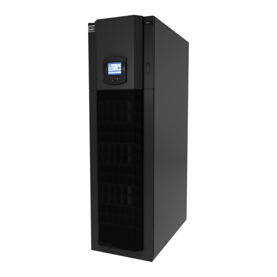
- Page 1 Precision Cooling For Business-Critical Continuity™ Liebert ® ™ User Manual–60Hz, 24-Inch Wide, Air-Cooled, Water/Glycol-Cooled and Chilled Water...
- Page 2 - 25 D ODEL UMBER OMENCLATURE IGIT ONFIGURATION UMBER Model # Part 1 * Model Details Model # Part 2 * Digits 1-2 - Unit Family Digit 17 - High-Voltage Options ® ™ Liebert = CR L or A = NO dual-float condensate pump (for units without humidifier), 5kA SCCR** Digits 3-5 - Nominal Capacity, kW DX = 020, 035...
-
Page 3: Table Of Contents
TABLE OF CONTENTS CRV C ........4 IEBERT OMPONENT OCATION... - Page 4 Remote Rack Sensor Wiring ..........44 9.5.1 DIP Switch Settings .
- Page 5 14.3 Maintenance Schedule ............108 14.4 Inspect and Replace the Air Filter .
- Page 6 Figure 20 Chilled water connections............31 Figure 21 Chilled water circuit .
- Page 7 Figure 70 Diagnostics / service mode parameters screen - Page 4 ....... . . 81 Figure 71 Diagnostics / service mode parameters screen - Page 5 .
- Page 8 TABLES Table 1 Dry weight, all model types, ± 5% ........... 6 Table 2 Center of gravity .
- Page 9 Important Safety Instructions MPORTANT AFETY NSTRUCTIONS SAVE THESE INSTRUCTIONS This manual contains important safety instructions that should be followed during the installation and maintenance of the Liebert CRV. Read this manual thoroughly before attempting to carry out any operations on the Liebert CRV, including installation and operation. Retain this manual for the entire service life of the Liebert CRV.
- Page 10 Important Safety Instructions WARNING Arc flash and electric shock hazard. Can cause injury and death. Disconnect local and remote power supplies and wear appropriate personal protective equipment per NFPA 70E before working within. Before proceeding with installation, read all instructions, verify that all the parts are included and check the nameplate to be sure the voltage matches available utility power.
- Page 11 Improper installation, application and service practices can result in water leakage from the unit. Do not locate the Liebert CRV directly above any equipment that could sustain water damage. Emerson recommends installing monitored leak detection equipment for the unit and supply lines. NOTICE Risk of frozen fluids.
-
Page 12: Liebert Crv Component Location
Liebert CRV Component Location CRV C IEBERT OMPONENT OCATION Figure 1 Component location, common components—All models ® Liebert iCOM control display Electric box Evaporator / CW coil Condensate pump Electric heaters Humidifier distributor Top humidifier water supply, condensate pump drain Drain trays, two places EC plug fans Bottom electrical entrance... -
Page 13: Figure 3 Component Location - Liebert Cr035Rw, Cr020Rw Water/Glycol-Cooled Units
Liebert CRV Component Location Figure 3 Component location - Liebert CR035RW, CR020RW water/glycol-cooled units Top water/glycol connections Compressor Brazed plate condenser Bottom water/glycol connections Water/glycol valve Refrigerant receiver Air filters Vibasorber Thermostatic expansion valve Sight glass Filter dryer Humidity/temperature sensor Bottom humidifier water supply Figure 4 Component location - Liebert CR040RC chilled water units... -
Page 14: Figure 5 Overall Dimensions / Service Area
Liebert CRV Component Location Figure 5 Overall dimensions / service area 25-9/16" 35-9/16" (650mm) (903mm) 13-3/4" (350mm) 78-3/4" (2000mm) Rear 25-9/16" (650mm) 3-15/16" Front (100mm) Door Fully Open 107-5/16" 12" (2725mm) (305mm) 46-1/4" 46-1/4" (1175mm) 3" (1175mm) 23-5/8" (75mm) (600mm) 21-5/8"... -
Page 15: Introduction
Introduction NTRODUCTION Product Description The Liebert CRV is a precision cooling unit available in compressorized (air-, water- or glycol-cooled) and chilled water configurations to be installed within a row of high-density computing racks in a “hot aisle-cold aisle” configuration. Air enters the rear of the Liebert CRV from the hot aisle, is filtered, cooled and conditioned, then discharged into the cold aisle. -
Page 16: Inspection And Unpacking
Examine the packaging for any signs of mishandling or damage. Inspect all items for damage, visible or concealed. Report any damage immediately to the carrier and file a damage claim. Send a copy of the claim to Emerson Network Power or your Emerson representative. 3.1.1 Packing Material All material used to package this unit is recyclable. -
Page 17: Handling The Unit While It Is Packaged
Inspection and Unpacking • Always keep the packaged Liebert CRV upright and never leave it outdoors. • Be aware of the center of gravity indicated on the package and in Table 2 below: Table 2 Center of gravity Distance from lower right front corner, ± 2 in. (51m) Model no. -
Page 18: Moving The Unit Using Rigging
Inspection and Unpacking Moving the Unit Using Rigging CAUTION Risk of sharp edges, splinters and exposed fasteners. Can cause personal injury. Only properly trained and qualified personnel wearing appropriate safety headgear, gloves, shoes and glasses should attempt to move, lift or remove packaging from the Liebert CRV or prepare the unit for installation. -
Page 19: Removing The Unit From The Skid
Inspection and Unpacking Figure 10 Unpacking the Liebert CRV 197023 Rev. 4 Removing the Unit from the Skid WARNING Risk of top-heavy unit falling over. Can cause equipment damage, personal injury and death. Read all of the following instructions before attempting to move, lift or remove packaging from the Liebert CRV. -
Page 20: Reattach The Baffle Panel
Inspection and Unpacking Figure 11 Removing the unit from the skid Step 5 Step 8 Step 1 4 Bolts on Each Side Secure the Tie-Down Bracket to the Skid M17 Socket M13 Socket Step 8 Step 15 197023 Rev. 4 Reattach the Baffle Panel Once the Liebert CRV has been moved to where it will be installed, the baffle panel can be reattached. -
Page 21: Prepare The Liebert Crv For Installation
Prepare the Liebert CRV for Installation REPARE THE IEBERT NSTALLATION 1. Open the display door and remove the lower front baffle panel using a 10mm nutdriver or T30 Torx Bit to prepare for installation. 2. Open the rear panel, referring to Figure 10. The documents are located inside the display door. 3. -
Page 22: Piping
Careful planning of the piping layout under the raised floor is required to prevent the airflow from being blocked. When installing piping on the subfloor, Emerson recommends installing the pipes in a horizontal plane rather than stacked one above the other. Whenever possible, the pipes should be run parallel to the airflow. -
Page 23: Condensate Piping-Field-Installed
• Drain line may contain boiling water. Use copper or other suitable material • Drain line must comply with local building codes • Emerson recommends installing under-floor leak detection equipment Gravity Drain—Units Without Factory-Installed Condensate Pump • 3/4" FPT drain connection is provided on units without optional factory-installed condensate pump with infrared humidifier or no humidifier;... -
Page 24: Requirements Of Systems Using Water Or Glycol
Piping 5.1.3 Requirements of Systems Using Water or Glycol These guidelines apply to the field leak checking and fluid requirements for field piping systems, including Liebert chilled water, condenser (water or glycol) and drycooler circuits. General Guidelines • Equipment damage and personal injury can result from improper piping installation, leak check- ing, fluid chemistry and fluid maintenance. - Page 25 Liebert unit fluid circuits should be checked for leaks at installation as described below. NOTE During leak checking of field-installed piping, Emerson recommends that the unit be isolated using field-installed shutoff valves. When the Liebert units are included in a leak test, use of fluid for pressure testing is recommended.
-
Page 26: Refrigerant Connections
Refrigerant Connections EFRIGERANT ONNECTIONS WARNING Risk of explosive discharge from high-pressure refrigerant. Can cause injury or death. This unit contains fluids and/or gases under high pressure. Relieve pressure before working with piping. WARNING Risk of refrigerant system rupture or explosion from overpressurization. Can cause equipment damage, injury and death. -
Page 27: Piping Guidelines-Air-Cooled Units
Refrigerant Connections Piping Guidelines—Air-Cooled Units • Indoor unit ships with a nitrogen holding charge; do not vent the evaporator until all refrigerant piping is in place, ready for connection to the unit and condenser • Use copper piping with high temperature brazed joints •... -
Page 28: General Layout
Refrigerant Connections 6.2.1 General Layout 1. Piping must be Type ACR copper tubing and sized per Tables 7, 8, 9 and 10. NOTE All field-installed piping must comply with applicable national, state and local codes. Use the shortest possible refrigeration pipelines to minimize the total charge of refrigerant and the number of pressure drops. -
Page 29: Pipe Diameter And Thickness
Refrigerant Connections Figure 16 Pipeline air conditioner - condenser COND (Distance) D = A + B + C CDT = Conditioner COND = Condenser 6.2.2 Pipe Diameter and Thickness WARNING Risk of explosive discharge. Can cause equipment damage, injury or death. Use only Type ACR copper tubing sized per Tables 7, 8, 9 and 10 for pipes connecting the Liebert CRV and the condensing unit. -
Page 30: R-410A
Refrigerant Connections Table 9 Piping and refrigerant sizes for Liebert air-cooled, VFD control condensers with R-410A Condenser Piping Connection Sizes, Cu, O.D. Entering Hot Gas Returning Liquid Condenser Model # Line, in. (mm) Line, in. (mm) TCSV28K 1-1/8 (28.6) 7/8 (22.2) TCSV60K 1-1/8 (28.6) 7/8 (22.2) -
Page 31: Installing Piping
Refrigerant Connections 6.2.3 Installing Piping The following operations must be carried out by an experienced refrigeration technician. NOTICE Risk of oil contamination with water. Can cause equipment damage. The piping must not be open to the atmosphere for extended periods because the Liebert CRV requires POE (polyol ester) oil. -
Page 32: Figure 17 Connections—Air-Cooled Models
Refrigerant Connections Figure 17 Connections—air-cooled models Unsolder when connecting Rear through bottom 1-1/8" (28mm) 23-5/8" 9-3/4" 12-3/4" (600mm) 1-3/4" 2-15/16" (248mm) (325mm) 3-1/4" (83mm) 3-1/16" 17-5/16" (44mm) (74mm) 8-7/8" (77mm) (440mm) (226mm) 9-1/2" 9-5/16" (242mm) (237mm) 5-1/8" 2-11/16" 46-1/4" (130mm) (69mm) or HS (1175mm) -
Page 33: Table 11 Unit Connections, Air-Cooled Models
Refrigerant Connections Table 11 Unit connections, air-cooled models Unit Connections CR20A (50Hz) CR35A (50Hz) CR20A (60Hz) CR35A (60Hz) Refrigerant Liquid 12mm O.D. Cu Sweat 16mm O.D. Cu Sweat 1/2" O.D. Cu Sweat 5/8" O.D. Cu Sweat Line Inlet Refrigerant Gas 16mm O.D. -
Page 34: Vacuum And Refrigerant Charge
Refrigerant Connections Vacuum and Refrigerant Charge NOTICE Risk of improper refrigerant charge. Can cause equipment damage and reduced efficiency. Check the refrigerant type to be used on the data plate of the air conditioner and on the refrigerating compressor. Table 12 R-410A refrigerant and oil charge for air-cooled models Base Oil Charge Weight of Oil to Add for... -
Page 35: Evacuation Air-Cooled Models
Refrigerant Connections Figure 18 Connections for vacuum creation and refrigerant charge Suction and Supply Line Connections Thermostatic Valve Connection Liquid Line Connection 6.3.1 Evacuation Air-Cooled Models Variable Fan Speed Control Leak Check and Evacuation Procedure Proper leak check and evacuation can be accomplished only with all system solenoid valves open and check valves accounted for. - Page 36 When adding liquid refrigerant to an operating system, it may be necessary to add the refrigerant through the compressor suction service valve. Care must be exercised to avoid damage to the compressor. Emerson recommends connecting a sight glass between the charging hose and the compressor suction service valve. This will permit adjustment of the cylinder hand valve so that liquid can leave the cylinder while allowing vapor to enter the compressor.
-
Page 37: Water
Water Connections ATER ONNECTIONS Table 16 Water connection options Liebert CRV Option Top Connections Bottom Connections Condensate Pump Available Available and Humidifier Condensate Pump Available Available and No Humidifier No Condensate Pump Not Available Available and No Humidifier Table 17 Volume of CRV internal water circuits Model Volume... -
Page 38: Glycol Mixture
• The water pressure must be 29-145psi (2-10 bar). If water pressure is outside this range, contact Emerson for technical support. • The required water flow at different temperatures is available from Emerson. • If water temperature is very low, insulate both pipes. -
Page 39: Chilled Water Connections: Chilled Water Units
Water Connections Chilled Water Connections: Chilled Water Units Figure 20 Chilled water connections Top Connections Bottom Rear Connections Refer to Figure 21 when performing these installation steps: • Use copper tubing or steel pipe. • Place the tubing on supporting saddles. •... -
Page 40: Figure 22 Air Bleeding Valve Position Cw
Water Connections Figure 22 Air bleeding valve position CW REAR VIEW ® ™ Liebert... -
Page 41: Figure 23 Connections—Water/Glycol Models
Water Connections Figure 23 Connections—water/glycol models 6-1/8" 4-1/8" (155mm) (105mm) Piping and electrical 1-1/8" connections available at (28mm) Rear the top and bottom of unit. 12-3/4" 9-3/4" (325mm) (248mm) 1-3/4" Top Connections (44mm) 8-7/8" 3-1/4" 7-13/16" 17-5/16" (226mm) 2-15/16" (83mm) (199mm) (440mm) (74mm) -
Page 42: Table 19 Unit Connections, Water/Glycol-Cooled Models
Water Connections Table 19 Unit connections, water/glycol-cooled models Unit Connections CR20W (50Hz) CR35W (50Hz) CR20W (60Hz) CR35W (60Hz) Water/Glycol Coolant Supply 32mm GAS F 1-1/4" FPT Water/Glycol Coolant Return 32mm GAS F 1-1/4" FPT Gravity Coil Pan Drain 20mm I.D. 1"... -
Page 43: Figure 24 Connections—Chilled Water Models
Water Connections Figure 24 Connections—chilled water models Piping and electrical connections available 6-1/8" 4-1/8" (155) (105) at the top and bottom of the unit. REAR 1-1/8" (28) 9-3/4" (325) (248) TOP CONNECTIONS 12-3/4" 1-3/4" 3-1/4" (83) 2-15/16" 8-7/8" 17-5/16" (44) 3-1/16"... -
Page 44: Figure 25 Recommended Drycooler Installation
Water Connections Table 20 Unit connections, chilled water models Unit Connections CR040C (50 Hz) CR040C (60 Hz) Chilled Water Supply 32mm GAS F 1-1/4" FPT Chilled Water Return 32mm GAS F 1-1/4" FPT Gravity Coil Pan Drain 20mm I.D. 1" MPT Gravity Humidifier Drain 22mm I.D. -
Page 45: Electrical Onnections
Electrical Connections LECTRICAL ONNECTIONS Electrical connections WARNING Arc flash and electric shock hazard. Can cause injury and death. Disconnect local and remote power supplies and wear appropriate personal protective equipment per NFPA 70E before working within. Before proceeding with installation, read all instructions, verify that all the parts are included and check the nameplate to be sure the voltage matches available utility power. -
Page 46: Power Supply Cable Connections
Electrical Connections Figure 27 Power and control cable entry points and routing High Voltage Top Low Voltage Top High Voltage Low Voltage Channel Entry Port Entry Port Top Entry Port opening provides access ® to the Liebert IntelliSlot card housing Low voltage cables are routed through a channel in the side panel to... -
Page 47: Protective Features Of The Electrically Commutated Fans
Electrical Connections Protective Features of the Electrically Commutated Fans The EC fans are protected against: • Overtemperature of electronics • Overtemperature of motor • Locked rotor protection • Short circuit at the motor output When any of these failures occurs, the motor stops, electronically, with no potential for separation, and the status relay is released. -
Page 48: Startup
Startup TARTUP Initial Startup WARNING Risk of hair, clothing and jewelry entanglement with high speed rotating fan blades. Can cause equipment damage, serious injury or death. Keep hair, jewelry and loose clothing secured and away from rotating fan blades during unit operation. -
Page 49: Automatic Restart
Startup Checks to Perform after Startup Once the system is operating under load, check the various components, as follows: 1. Verify that the fans are operating properly. 2. Ensure that the temperature and relative humidity are being controlled, and that the humidifier (optional) and heating steps (optional) operate when required. -
Page 50: Chilled Water Valve: Chilled Water Models
Startup Chilled Water Valve: Chilled Water Models The 3-way valve controls the chilled water flow and operates as follows (refer to Figure 4): • When the valve is fully open (i.e., maximum chilled water flow), the actuator slot is set to “1.” •... -
Page 51: Figure 31 Adjust The Baffles To Ensure Correct Airflow Direction
Startup To adjust the baffles: 1. Open the door containing the Liebert iCOM ® display. 2. Remove the two screws holding a baffle panel segment in place. 3. Slide out the baffle segment. 4. There is one screw on each side of the baffle, as shown in Figure 31. Remove the screws and rotate the baffle segment around its horizontal axis to change the airflow direction. -
Page 52: Remote Rack Sensor Wiring
Rack sensors help combat cooling problems related to recirculation air, uneven rack loading and air distribution. The 2T rack sensors are intended for cold aisle use only. While installing the rack sensors is optional, Emerson recommends that they be installed. Installations with multiple Liebert CRV cooling units should be connected in a Unit-to-Unit (U2U) Ethernet network to leverage all of the Liebert iCOM ®... -
Page 53: Dip Switch Settings
Startup Figure 33 Figure 2T rack sensor Back Each temperature probe wire is 1830mm (6 feet) long 2T Sensor (3-3/8") Front View Max. depth Temperature sensing probe 41 (1-5/8") Source DPN001983 rev0 9.5.1 DIP Switch Settings Three 2T sensor housings are included with each Liebert CRV. The DIP switches in these sensors have been preset at the factory. -
Page 54: Set 2T Rack Sensor Identities-Dip Switch Settings
Startup 9.5.2 Set 2T Rack Sensor Identities—DIP Switch settings 1. Confirm the DIP switches are set correctly for 2T sensors numbered 1, 2 and 3. 2. If additional sensors are to be connected to a cooling unit: a. Apply numbered stickers to the sensor housings, corresponding to sensor chain position. b. -
Page 55: Route The Can Bus Wire Into The Cooling Unit
Startup Figure 36 Termination jumper setting Circuit board inside display housing Circuit board inside 2T sensor housing Termination Jumper in the Terminated Position Terminated Unterminated 9.5.4 Route the CAN bus wire into the cooling unit The CAN bus sensors connect to the open CAN port on the back of the unit display panel. The Display comes “Terminated”... -
Page 56: Installing 2T Sensors On Racks
Startup 9.5.5 Installing 2T sensors on racks Both temperature sensors attached to a 2T sensor housing are to be installed on 1 rack. The sensor can be attached to the inside or outside of the rack's front door. • One temperature sensor is to be attached near the top of the rack’s front door by using a cable tie to secure the wire to the perforation (approx. -
Page 57: Remote Rack Sensor Operation And Rack View Setup
Startup Located in the Service / Rack Setup Menu of the Liebert iCOM display, the sensors can be set up to ® either display or control temperature, give them a rack name and draw a rack layout that can be viewed in the User menu. -
Page 58: Figure 40 Rack Setup Screen, Page 3 Of 3
Startup Figure 40 Rack setup screen, page 3 of 3 Rack Setup (page 3 of 3) UNIT 01 Liebert CRV = CRV Assign Names: 01-06 No Sensors = NoS 07-12 No rack = [blank] 13-18 Sensor Note = 01-10 19-22 DC01 DC03 DC05... -
Page 59: Liebert Icom ® Control
® Liebert iCOM Control ® 10.0 L IEBERT I ONTROL The Liebert CRV is equipped with the most advanced Liebert iCOM control system. The large Liebert iCOM display is standard on the Liebert CRV. Each Liebert CRV contains a return air temperature and humidity sensor, supply air temperature sensor and three remote rack sensors. -
Page 60: Navigating Through The Liebert Icom Menus
® Liebert iCOM Control ® Figure 42 Liebert iCOM default screen symbols cooling freecooling maintenance electric heat hot water dehumidification humidification 10.1 Navigating Through the Liebert iCOM Menus Liebert iCOM shows icons and text for monitoring and controlling your Liebert cooling units or network of cooling units. -
Page 61: Entering A Password
® Liebert iCOM Control change the unit being viewed. Pressing the ESC key will go back a level. Figures 44 and 45 show the Liebert iCOM ® control menus for a stand-alone large display and for a networked large display, respectively. -
Page 62: Figure 44 Menu Tree—Large Display, Stand-Alone
® Liebert iCOM Control Figure 44 Menu tree—Large display, stand-alone Unit 1 will be displayed Status Menu – System View in the top left corner of the screen. Status Menu Unit 1 View User Menu Service Menu Advanced Menu Unit 1 Unit 1 Unit 1 Password... -
Page 63: Viewing Multiple Units With A Networked Large Display
® Liebert iCOM Control 10.1.4 Viewing Multiple Units with a Networked Large Display When you first wake up the control, press the ESC key to return to the System view Status menu. This view shows an average of all the units on the network and any alarms present. To view a specific unit on the network, press either the enter key or down arrow key. -
Page 64: Figure 46 User Menu Icons
® Liebert iCOM Control Figure 46 User menu icons °C / °F EVENT % RH ALARMS User Menu password: 1490 RACK 1 2 3 4 VIEW ACTIVE ALARMS Table 23 User menu icons Icon Name Description °C / °F % RH Setpoints View and change temperature and humidity setpoints Displays the various part numbers of the components/parts... -
Page 65: Figure 47 Service Menu Icons
® Liebert iCOM Control Table 23 User menu icons (continued) Icon Name Description RACK Rack View Allows viewing data, collected by sensors, about rack status VIEW Contains key contact information for local service, including names Service Contact Info and phone numbers ®... - Page 66 ® Liebert iCOM Control Table 24 Service menu icons (continued) Icon Name Description Sensor Calibration/Setup Allows calibration of sensors + / - NETWORK System/Network Setup Allows setup and U2U communication for multiple units Options Setup Allows setup of component operation Rack Setup Label racks, establish settings for sensors Contains key contact information for local service, including...
-
Page 67: Liebert Icom ® Display Readout
® Liebert iCOM Control ® 10.2 Liebert iCOM Display Readout The Liebert iCOM controller for the Liebert CRV supports multiple main screen layouts. The screens are a graphical representation of the Liebert CRV, selectable to show unit operation with or without rack sensors, unit operation with a rack sensor summary, historical temperature and humidity trending or trending the screens used on other Liebert products. - Page 68 ® Liebert iCOM Control ® Figure 49 Liebert iCOM menu components for Liebert CRV Return Temperature and Humidity UNIT 1 Summary of Rack Liebert Sensor Readings Rack Inlet Temp 98°F Average : 71°F 20%RH Maximum: 73°F Minimum: 69°F °F Supply Temperature Fan Speed and Humidity Cooling Capacity...
-
Page 69: Liebert Icom ® Control Setup
Using the supply and remote rack sensors in this de-coupled mode is the preferred method for controlling the Liebert CRV in a hot / cold aisle configuration. In addition to this configuration Emerson has provided additional flexibility for other applications shown in Table 25. -
Page 70: Event Log
® Liebert iCOM Control The supply temperature Setpoint may require adjusting since it will be dependent on the distance of the CRV to the server racks being cooled. This temperature will also be dependant on rack blanking panels, server population and if containment is being used Table 25 Controlling sensor settings Cooling Control... - Page 71 ® Liebert iCOM Control Calculating Unit Wellness Liebert iCOM ® keeps tabs on the condition of a cooling unit, determining its wellness and projecting when service will be needed, for the entire unit as well as for individual components. This assists in scheduling maintenance calls and helps pinpoint components likely to require service.
-
Page 72: Liebert Crv Operation-Liebert Icom ® Control
Control 10.7.1 Cooling The cooling control of the Liebert CRV can be managed from any of the temperature sensors. Emerson recommends using the supply temperature sensor to control the cooling capacity of the Liebert CRV. The supply temperature is an accurate representation of the actual heat rejection the Liebert CRV needs to perform at an optimal level. -
Page 73: Liebert Icom ® User Menu Screens
® Liebert iCOM Control ® 10.8 Liebert iCOM User Menu Screens User menus report general cooling unit operations and status. The user menu password is 1490. The User menu parameter tables in this manual may differ from the display on your cooling unit. The Liebert iCOM functions with several Liebert Precision Cooling units, each with its own set of control commands. -
Page 74: Figure 53 Sensor Data Parameters Screen
® Liebert iCOM Control View Network View Network—The view network screen provides an overview of the Liebert iCOM ® network and a status of each unit. This screen will provide the unique unit name given to the unit. If no name is given, then only the unit number will be displayed. -
Page 75: Figure 54 Display Setup Parameters Screen
® Liebert iCOM Control Figure 54 Display setup parameters screen DISPLAY SETUP SYSTEM S401 Language ENGLISH (US) S402 Date 7/17/2010 S403 Time 09:20:19 S404 Temperature Indication °F S405 Display Contrast S406 Buzzer Frequency Off/ 0 S407 Backlite Off after 30 min S408 Screen Rack View... -
Page 76: Liebert Icom ® Service Menu Screens
® Liebert iCOM Control Figure 55 Total run hours parameters screen TOTAL RUN HOURS UNIT 01 U501 Actual Hours Limit U502 Fan Motor (s) 3513 U503 Compressor 1 3511 U504 U505 Chilled Water U506 Electric Heater U507 U508 U509 Humidifier U510 Dehumidification U511... -
Page 77: Figure 57 Setpoints Parameters Screen - Page 1
® Liebert iCOM Control Figure 57 Setpoints parameters screen - Page 1 SETPOINTS (page 1 of 4) UNIT 01 S101 PASSWORD (Actual Level 0) ???? S102 Temperature Setpoint 68 °F Temperature Control Sensor Remote Sensor S103 S104 Temperature Control Type Proportional S105 Temperature Deadband... -
Page 78: Figure 58 Setpoints Parameters Screen - Page 2
® Liebert iCOM Control Figure 58 Setpoints parameters screen - Page 2 SETPOINTS (page 2 of 4) UNIT 01 S112 PASSWORD (Actual Level 0) ???? S113 Humidity Setpoint S114 Humidity Control Type S115 Humidity DeadBand S116 Humidity Proportional Band S117 Humidity Integration Time 0min S118... -
Page 79: Figure 59 Setpoints Parameters Screen - Page 3
® Liebert iCOM Control Figure 59 Setpoints parameters screen - Page 3 SETPOINTS (page 3 of 4) UNIT 01 S123 PASSWORD (Actual Level 0) ???? S124 Fan Control Type Auto S125 Fan Control Sensor Remote Sensor S126 Fan Regulation Type S127 Fan Delta °F... -
Page 80: Figure 60 Setpoints Parameters Screen - Page 4
® Liebert iCOM Control Figure 60 Setpoints parameters screen - Page 4 SETPOINTS (page 4 of 4) UNIT 01 S134 PASSWORD (Actual Level 0) ???? S135 MIN at CFC for EC Fan S136 STD at CFC for EC Fan 100 % S137 High Temp Limit Approach Supply... -
Page 81: Figure 61 Standby Settings / Lead-Lag Parameters Screen
® Liebert iCOM Control Figure 61 Standby settings / lead-lag parameters screen STANDBY SETTINGS/LEAD-LAG SYSTEM S501 PASSWORD (Actual Level 0) ???? S502 Number of Standby Units S503 Rotation Frequency S504 Rotate at (hour ) S505 Rotate at (minute) S506 Rotate by S507 Perform one Rotation S508... -
Page 82: Figure 62 Wellness Basic Settings Screen- Page 1
® Liebert iCOM Control Figure 62 Wellness basic settings screen- Page 1 WELLNESS basic settings (page 1 of 5) SYSTEM S001 PASSWORD (Actual Level 0) ???? S002 Maintenance Frequency Per Year S003 Max Bonus S004 Max Penalty S005 Last Maintenance 06/14/2010 S006 Service Engineer... -
Page 83: Figure 63 Wellness Motor Settings Parameters Screen - Page 2
® Liebert iCOM Control Figure 63 Wellness motor settings parameters screen - Page 2 WELLNESS motor settings (page 2 of 5) UNIT 1 S012 PASSWORD (Actual Level 0) ???? S013 Number of Starts S014 Run Hours 3376 hrs S015 Average Run Time 9645 min S016 Starts per Day Best... -
Page 84: Figure 64 Wellness Compressor 1 Settings Parameters Screen - Page 3
® Liebert iCOM Control Figure 64 Wellness compressor 1 settings parameters screen - Page 3 WELLNESS compressor1 settings (page 3 of 5) UNIT 1 S023 PASSWORD (Actual Level 0) ???? S024 Number of Starts S025 Run Hours 3374 hrs S026 Average Run Time 9201 min S027... -
Page 85: Figure 65 Wellness Electric Heater 1 Settings Parameters Screen - Page 4
® Liebert iCOM Control Figure 65 Wellness electric heater 1 settings parameters screen - Page 4 WELLNESS el heater 1 settings (page 4 of 5) UNIT 1 S034 PASSWORD (Actual Level 0) ???? S035 Number of Starts Screen displayed S036 Run Hours 0hrs only if unit is... -
Page 86: Figure 66 Wellness Humidifier Settings Parameters Screen - Page 5
® Liebert iCOM Control Figure 66 Wellness humidifier settings parameters screen - Page 5 WELLNESS humidifier settings (page 5 of 5) UNIT 1 S045 PASSWORD (Actual Level 0) ???? S046 Number of Starts 14404 Screen displayed S047 Run Hours 154 hrs only if unit is equipped with S048... -
Page 87: Figure 67 Diagnostics / Service Mode Parameters Screen - Page 1
® Liebert iCOM Control Figure 67 Diagnostics / service mode parameters screen - Page 1 DIAGNOSTICS/SERVICE MODE (page 1 of 6) UNIT 01 S301 PASSWORD Actual Level 0) ???? S302 HP 1 Alarm Code S303 LP 1 Alarm Counter S304 HT1 Alarm Counter S305 12h Dehum Counter... -
Page 88: Figure 68 Diagnostics / Service Mode Parameters Screen - Page 2
® Liebert iCOM Control Figure 68 Diagnostics / service mode parameters screen - Page 2 DIAGNOSTICS/SERVICE MODE (page 2 of 6) UNIT 01 S312 PASSWORD Actual Level 0) ???? S313 Manual Mode S314 Motor(s) S315 Compressor 1 S316 Compressor 1 Capacity S317 Compressor 1 Cycle Ramp S318... -
Page 89: Figure 70 Diagnostics / Service Mode Parameters Screen - Page 4
® Liebert iCOM Control Humidifier Fill—This activates just the humidifier water source solenoid valve which fills the humidifier pan or canister with water. Humidifier—This activates the humidifier system in its entirety. Humidifier Drain—This activates just the humidifier drain solenoid in the case of the steam generating humidifier, allowing water to drain from the canister. -
Page 90: Figure 71 Diagnostics / Service Mode Parameters Screen - Page 5
® Liebert iCOM Control Figure 71 Diagnostics / service mode parameters screen - Page 5 DIAGNOSTICS/SERVICE MODE (page 5 of 6) UNIT 01 S345 PASSWORD Actual Level 0) ???? S346 Status Remote Shutdown S347 Status Airflow 1 S348 Status Airflow 2 S349 Status Filter S350... -
Page 91: Figure 73 Set Alarms Parameters Screen - Page 1
® Liebert iCOM Control Figure 73 Set alarms parameters screen - Page 1 SET ALARMS (page 1 of 4) UNIT 01 S201 PASSWORD (Actual Level 0) ???? S202 S203 S204 S205 Tem/Hum Events Enabled S206 High Supply Temperature 80 °F S207 Low Supply Temperature 46 °F... -
Page 92: Figure 74 Set Alarms Parameters Screen - Page 2
® Liebert iCOM Control Figure 74 Set alarms parameters screen - Page 2 SET ALARMS (page 2 of 4) UNIT 01 S211 PASSWORD (Actual Level 0) ???? S212 Customer Input 1 Smoke Alarm S213 Customer Input 1 active when Closed S214 Customer Input 2 Fire Alarm... -
Page 93: Figure 76 Set Alarms Parameters Screen - Page 4
® Liebert iCOM Control Figure 76 Set alarms parameters screen - Page 4 SET ALARMS (page 4 of 4) UNIT 01 S234 PASSWORD (Actual Level 0) ???? S235 DELAY EN-DIS TYPE S236 CALL SERVICE ENABLE S237 HIGH TEMPERATURE ENABLE S238 S239 HEAT REJ VFD ENABLE... -
Page 94: Figure 77 Sensor Calibration / Setup Parameters - Page 1
® Liebert iCOM Control Figure 77 Sensor calibration / setup parameters - Page 1 SENSOR CALIBRATION/SETUP (page 1 of 4) UNIT 01 PASSWORD Actual Level 0) ???? S601 S602 Return Temperature +0°F Calibrated Return Temperature 77°F S603 Return Humidity +0.0% S604 S605 Calibrated Return Humidity... -
Page 95: Figure 79 Sensor Calibration / Setup Parameters - Page 3
Supply T Sensor PTC or NTC—This parameter sets the type of sensor that is connected to the unit. It is set at the factory as NTC and should be changed only by a certified Emerson technician. Supply T Sensor—This parameter can provide an offset to the actual sensor reading to calibrate the unit’s sensor to other sensors. -
Page 96: Figure 80 Sensor Calibration / Setup Parameters - Page 4
® Liebert iCOM Control Figure 80 Sensor calibration / setup parameters - Page 4 SENSOR CALIBRATION/SETUP (page 4 of 4) UNIT 01 S634 PASSWORD Actual Level 0) ???? S635 Rack Temperature Sensor 1B °F 77°F S636 Rack Temperature Sensor 2B °F 78°F S637... -
Page 97: Figure 82 System / Network Setup Parameters—Large Display Only System - Page 2
® Liebert iCOM Control Network Safe—This parameter saves or loads network settings for the display that have been modified from the factory defaults to an internal file that can be downloaded / uploaded using the Liebert iCOM Service Tool. Selecting “Save” will write the settings to the internal storage file and ®... -
Page 98: Figure 83 System/Network Setup Parameters Unit- Page 1
® Liebert iCOM Control Figure 83 System/Network setup parameters Unit- Page 1 SYSTEM / NETWORK SETUP (page 1 of 2) UNIT 01 S823 PASSWORD (Actual Level 0) ???? S824 Monitoring Address S825 Monitoring Timeout /Handshake S826 S827 Unit Name UNIT S828 S829 S830... -
Page 99: Figure 84 System/Network Setup Parameters Unit - Page 2
® Liebert iCOM Control Figure 84 System/Network setup parameters Unit - Page 2 SYSTEM / NETWORK SETUP (page 2 of 2) UNIT 01 S834 PASSWORD (Actual Level 0) ???? S835 Monitoring Protocol Velocity V4 S836 IP Address 10.203.062.178 S837 Netmask 255.255.255.192 S838 Gateway... -
Page 100: Figure 85 Rack Overview, Page 1
® Liebert iCOM Control Figure 85 Rack Overview, Page 1 Rack Overview (page 1 of 1) UNIT 01 CC21 BB01 BB02 BB03 Cold Aisle EC50 EC51 All temperatures shown in °F This screen shows the rack label assigned to each rack and the temperature associated with the rack sensor. -
Page 101: Figure 87 Rack Setup, Page 2
® Liebert iCOM Control Figure 87 Rack Setup, Page 2 RACK SETUP (page 2 of 3) UNIT 01 Assign Sensors: 01-06 Liebert CRV = CRV 07-12 No Sensors = -2 13-18 No Rack 19-22 Sensor Node = 01-10 CC21 Cold Aisle Use the navigation keys to move from rack to rack . -
Page 102: Figure 89 Options Setup Parameters - Page 1
® Liebert iCOM Control Figure 89 Options setup parameters - Page 1 OPTIONS SETUP (page 1 of 2) UNIT 01 S401 PASSWORD Actual Level 0) ???? S402 S403 Low Pressure Alarm Delay 1min S404 S405 S406 Electric Stages S407 Heater ON at CFC -66 % S408 Water Detector... -
Page 103: Figure 90 Options Setup Parameters - Page 2
® Liebert iCOM Control Figure 90 Options setup parameters - Page 2 OPTIONS SETUP (page 2 of 2) UNIT 01 S412 PASSWORD Actual Level 0) ? ??? S413 WA and AL Relay Direct S414 S415 S416 S417 S418 S419 Dehumidification Enabled S420 Auto Restart Enabled S421... -
Page 104: Table 27 Service Contact Info Parameters
® Liebert iCOM Control Table 27 Service contact info parameters Function Range Large Display Small Display Imperial (metric) Page 1 of 1 Password PASSWORD None Austria Switzerland D Switzerland F Benelux D Benelux FL Germany France Country Country Hungary Italy Poland Spain United States... -
Page 105: Operation In Teamwork Mode
Operation in Teamwork Mode 11.0 O PERATION IN EAMWORK 11.1 Unit-to-Unit Network Wiring Liebert CRV’s can be connected in a unit-to-unit, or U2U, configuration, which allows multiple units to communicate with each other, sharing of local unit status and sensor readings. The U2U network will allow up to 32 units to be connected within a single group and up to 99 different groups to exists on the same physical network. -
Page 106: Wiring A Liebert Icom ® U2U Network
Operation in Teamwork Mode ® 11.3 Wiring a Liebert iCOM U2U Network A network switch is required to enable Ethernet unit-to-unit communication on one or more Liebert CRV’s. Each Liebert CRV requires two straight-through Ethernet cables from a network switch. One cable connects to port P64 on the Liebert iCOM input/output board and the other straight-through cable connects to the P64 port on the back of the large display (see Figure 92). -
Page 107: Teamwork Modes
Operation in Teamwork Mode Wall-Mount Large Display The Liebert CRV has a large display as standard equipment. Only large displays can be used for remotely monitoring and controlling cooling units connected on the same network. Each wall-mount large display requires 120V input power; Liebert provides an AC adapter wall plug. A straight- through Ethernet cable must be connected between the network switch and the P64 port on the back of the display. -
Page 108: Application Of Teamwork Modes
Operation in Teamwork Mode Figure 93 Teamwork modes and sensor management Average / Maximum of Liebert CRV Connected Sensors Average / Maximum of Teamwork Sensors Example: 72°F (22°C) Setpoint Teamwork Sensor Average = 74°F (23°C) Teamwork Sensor Maximum = 76°F (24°C) Sensor (one of 8) Liebert CRV 1... -
Page 109: Teamwork Mode 2
Operation in Teamwork Mode Figure 94 shows how two cooling units work together in Teamwork Mode 1. Since Unit 1 and Unit 2 are available to operate, the master unit, Unit 1, averages the temperature and humidity sensor readings from each unit. The master unit determines that a 60% call for cooling is required for the system. -
Page 110: Standby-Rotation
Operation in Teamwork Mode 11.4.5 Standby—Rotation Typical Standby (Lead/Lag) Function This function can be performed in any teamwork mode, including NO Teamwork. One or more units can be defined to be Standby; the normal status of standby units is Standby Off (fan off). -
Page 111: Operation
Operation 12.0 O PERATION Figure 95 Return air temperature and humidity sensor viewed from the rear of the unit The control system compares the relayed information with the programmed setpoint and proportional band values and performs one of the following operations: •... - Page 112 Operation • Humidification (optional)—The humidifier creates steam, which is distributed into the air stream via the steam distribution pipe. (See also Appendix A - Humidifier). The Liebert CRV’s humidification is activated when the measured temperature and humidity sensor has been calcu- lated to exceed the corresponding dew point setpoint.
-
Page 113: Alarms/Events
Operation 12.1 Alarms/Events The following alarms and events are supported by the Liebert iCOM control on the Liebert CRV. ® When an alarm is triggered the alarm sounds, the LED will flash red, an event will be written to the Event Log and the BMS will be notified. -
Page 114: Calibration And Regulation After Startup
Calibration and Regulation after Startup 13.0 C ALIBRATION AND EGULATION AFTER TARTUP The Liebert CRV has been factory-tested and calibrated, but it is very important to check, at startup, the superheating of the thermostatic valve (A/W versions). • For calibrations of instruments installed on the external condensers/drycoolers, refer to the man- ual for the equipment. -
Page 115: Maintenance
Maintenance 14.0 M AINTENANCE 14.1 Safety Instructions All maintenance operations must strictly observe national, state and local accident prevention regulations, especially the regulations concerning electrical systems, refrigerators and manufacturing resources. Air conditioning equipment maintenance may be performed only by authorized properly trained and qualified personnel. -
Page 116: Spare Parts
14.2 Spare Parts Only original spare parts made by Emerson Network Power may be used. Using third-party material can invalidate the warranty. When making seeking technical assistance, always refer to the component list supplied with the equipment, and specify the model number, serial number and, if available, the part number. -
Page 117: Inspect And Replace The Air Filter
Maintenance Table 28 Maintenance schedule Maintenance Period Monthly Every Every Component By User 3 Months 6 Months Annually Check compressor noise/vibrations Check oil level through compressor sight glass Adjust/tighten compressor/functional elements Check sight glass for problem detection Refrigerating Circuit Check starting/running amps Check refrigerating circuit main pressures Check compressor suction superheat Check discharge temperature... -
Page 118: Figure 97 Remove The Air Filters
Maintenance To extract the filters (refer to Figure 97: 1. Push up the upper filter. 2. Pull the bottom of the filter away from the Liebert CRV. 3. Pull it out of the unit. 4. Lift the lower filter up 5. -
Page 119: Condensate Drain And Condensate Pump Systems
Maintenance 14.5 Condensate Drain and Condensate Pump Systems 14.5.1 Condensate drain Check for and clear obstructions in tubing during routine maintenance. 14.5.2 Condensate Pump, Dual-Float Figure 99 Condensate pump 1. Disconnect power to the unit using the disconnect switch. 2. Check for and clear obstructions in gravity lines leading to the condensate pump. 3. -
Page 120: Dismantling The Unit
Maintenance 14.8 Dismantling the Unit The Liebert CRV has been designed and built to ensure continuous operation. The working life of some of the main components, such as the fan and the compressor, depends on proper maintenance. NOTICE Risk of release of hazardous substances into the environment. Can cause environmental pollution and violation of environmental regulations. - Page 121 Maintenance • Additional information located in a dedicated label of the unit (Reg. 1494/2007): a. Where fluorinated greenhouse gas is foreseen to be added to the equipment outside of the manufacturing site at the point of installation, a dedicated label accommodates notation of both the quantity (kg) pre-charged in the manufacturing plant and the quantity charged at the installation site, as well as the resulting total quantity of F-gas as a combination of the above-mentioned quantities, in a manner that conforms to legibility and indelibility.
-
Page 122: T Roubleshooting
Chilled water units: inlet water Check cooling water temperature temperature is too high Refrigerating circuit charge issue Contact your local Emerson representative Verify unit positioning/room configuration Cold air short-cycling issues Verify unit air baffles set-up Verify cold aisle containment seals (if applicable) -
Page 123: Table 30 Liebert Icom ® Medium Control Board Dipswitch Settings
Troubleshooting ® Table 30 Liebert iCOM medium control board DIPswitch settings Compressorized DIPswitch CRV models Chilled Water Number CR020 and CR035 Model-CR040 ® ™ Liebert... -
Page 124: Figure 100 General Diagram—Humidifier Operation
Humidifier A - H PPENDIX UMIDIFIER RINCIPAL OF PERATION When the Liebert iCOM ® calls, the cylinder fills to 100% of the Full Load Amperage (FLA) or to the top of the cylinder, whichever comes first. See Figure 100. If it reaches 100% FLA, the water heats and boils away to a level giving 80% FLA. -
Page 125: Figure 101 Water Connection To Humidifier
Humidifier A.1.1 Humidifier Water Supply and Plumbing The fill valve is sized for an extended water pressure range of 30 to 80 psi. For installations where water pressure is less than 15 psi, add a pressure boost pump and notify the factory;... - Page 126 The red light may come on during initial startup, but this does not mean the cylinder must be replaced. See 9.0 Startup and 12.0 Operation. Contact Emerson or your local Emerson representative to obtain a replacement cylinder. To obtain the correct cylinder, supply the cylinder model from the white three-digit label on the cylinder, or supply the model, voltage and serial number from the unit specification label.
-
Page 127: Figure 102 Sensor Pins, Cylinder Plugs
Humidifier Remove the Old Cylinder 1. Turn Off the water supply to the unit. 2. The old cylinder must be drained completely before removing. This is done by pushing the auto On/Off/Drain switch to the “drain” position. 3. When the cylinder is empty, push the auto On/Off/Drain switch to the Off position. 4. -
Page 128: Figure 103 Can Bus And Ethernet Cable Wiring
Humidifier A.1.6 Humidifier Troubleshooting Terms Used • FLA (Full Load Amps) are amps listed on the humidifier specification label. • Short cycling occurs when the humidifier’s “On time” is less than 10 minutes upon a call for humidity. To correct short cycling, all humidifiers have a capacity adjustment that allows the out- put of the humidifier to be reduced to as low as 20% of rated output, thus extending the “on time”... - Page 129 Humidifier TARTING OINT Auto On/Off/Drain switch in On position—unit will not fill: When the On/Off control circuit is made and the Auto On/Off/Drain switch is pushed to On, the 24V holding coil of the primary contactor should energize. The resulting magnetic pull closes the high voltage contacts with a distinct and audible “clunk.”...
-
Page 130: Table 31 Humidifier Troubleshooting
Humidifier Table 31 Humidifier troubleshooting Unit Status Lamp Yellow Green Symptom Corrective actions This usually happens on initial start-up after replacing the Maximum water level inside cylinder (normal). Water is concentrated with minerals cylinder. inside the cylinder. Let unit run; yellow light will disappear when the unit is at full output. -
Page 131: Table 32 Liebert Crv Electrical Data - 60Hz (Amps)
Electrical Data B - E PPENDIX LECTRICAL Table 32 Liebert CRV electrical data - 60Hz (Amps) Air-Cooled Units Water/Gylcol-Cooled Units Chilled Water Units CR035RA CR020RA CR035RW CR020RW CR040RC Voltage 460/3/60 208/3/60 460/3/60 208/3/60 460/3/60 208/3/60 460/3/60 208/3/60 460/3/60 208/3/60 Cooling with Dehumidifying, Condensate Pump, Reheat; with or without Humidifier 31.7 62.0 24.3... - Page 132 Electrical Field Connections Descriptions C - E PPENDIX LECTRICAL IELD ONNECTIONS ESCRIPTIONS TANDARD LECTRICAL ONNECTIONS (Source: DPN001884, Rev. 4, Page 1) 1. High Voltage Connection Through the Bottom of the Electric Panel—1-3/8" (34.9mm), 1-3/4" (44.5mm) 2-1/2" (64mm) diameter concentric knockout. 2.
-
Page 133: C.1 Standard Electrical Connections
Electrical Field Connections Descriptions NOTICE Risk of improper input power. Can cause equipment damage. The electronically commutated motors included in the Liebert CRV unit are suitable for connection to an electrical service providing input power to the unit with 300V or less line-to- ground potential only. -
Page 134: Figure 105 General Arrangement—Air-Cooled Units
Refrigeration and Hydraulic Circuits D - R PPENDIX EFRIGERATION AND YDRAULIC IRCUITS Figure 105 General arrangement—air-cooled units Outdoor Lee-Temp Condenser Outdoor VFD Condenser Head Pressure Optional Field-Installed Relief Valve Control Valve Check Valve Fusible Plug Condenser Coil VFD Transducer Condenser Coil Lee-Temp Receiver (Liebert Lee-Temp) (VFD) -
Page 135: Figure 106 General Arrangement—Water-Glycol Units
Refrigeration and Hydraulic Circuits Figure 106 General arrangement—water-glycol units Distributor Vibration Evaporator Coil Sensing Absorber Bulb CR020 Digital Rotalock Valve Solenoid Valve High- CR035 Digital Pressure Solenoid Valve External Equalizer Transducer Low Pressure Digital Transducer High-Pressure Switch Scroll Rotalock Valve Expansion Compressor Valve... -
Page 136: Figure 107 General Arrangement—Chilled Water
Refrigeration and Hydraulic Circuits Figure 107 General arrangement—chilled water Chilled Water Coil Air Bleed Valve Valve Fitting Blocker 2-Way Chilled Water 3-Way Chilled Water Disk Valve Configuration Valve Configuration Plug Pipe Chilled Water Return (Top of Unit Connection) Plug Pipe Chilled Water Return (Bottom of Unit Connection) Plug Pipe... - Page 137 Refrigeration and Hydraulic Circuits NOTES ® ™ Liebert...
- Page 138 Refrigeration and Hydraulic Circuits ® ™ Liebert...
- Page 140 Power Switching & Controls Services DC Power Infrastructure Management & Monitoring Precision Cooling Surge Protection Emerson, Business-Critical Continuity, Emerson Network Power and the Emerson Network Power logo are trademarks of Emerson Electric Co. or one of its affiliated companies. ©2009 Emerson Electric Co.