beautypg.com
Manuals
Brands
Emerson Manuals
Heat Pump
Copeland EazyCool OM 501 Series
Emerson Copeland EazyCool OM 501 Series Manuals
Manuals and User Guides for Emerson Copeland EazyCool OM 501 Series. We have
1
Emerson Copeland EazyCool OM 501 Series manual available for free PDF download: Application Manuallines
Emerson Copeland EazyCool OM 501 Series Application Manuallines (73 pages)
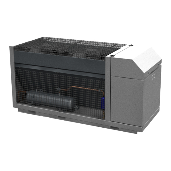
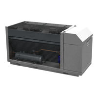
Large Outdoor Condensing Units
Brand:
Emerson
| Category:
Heat Pump
| Size: 5.29 MB
Table of Contents
Section 1
2
Table of Contents
2
About These Guidelines
6
Icon Explanation
6
General Instructions
7
Safety Statements
7
1 Safety Instructions
6
2 Product Description
8
Common Information about Copeland OM(T)E & OL(T)E Condensing Units
8
EU Ecodesign Directive 2009/125/EC
8
Product Range
8
Product Nameplate
8
Figure 1: Unit Nameplate
8
Nomenclature
9
Application Range
9
Qualified Refrigerants and Oils
9
Figure 2: Nomenclature OM & OL Units
9
Application Limits
10
Main Component Description
10
Bill of Material 501 - General Description
10
Housing
10
Figure 3: OM(T)E & OL(T)E Unit Housing
10
Figure 4: Main Components
11
Figure 5 : Open Condenser Segment
11
Compressor
12
Figure 6: Accessibility Main Components
12
Figure 7 : Open Compressor Compartment
12
Condenser Fan(S)
13
Figure 8 : Open Fan Safety Grid
13
Electrical Cabinet
14
Figure 9: Electrical Cabinet
14
Figure 10 : Open Electrical Cabinet
14
P&I Diagram for OM(T)Q Units
15
Figure 11: P&I Diagram for OM(T)E Units
15
P&I Diagram for OL(T)Q Units
16
Figure 12: P&I Diagram for OL(T)E Units
16
XCM25D Electronic Controller - Features
17
Description
17
Functionality
17
Figure 13: Electronic Controller
17
Main Control & Safety Features
18
Figure 14: XCM25D Controller Functionality Overview
18
Emergency Mode
20
Figure 15: Rescue Mode Activation
20
Heat Recovery Mode - Optional
21
Figure 16: Heat Recovery Implementation
21
XCM25D Electronic Controller - Programming
22
Programming the Local Display
22
Figure 17: Local Display
22
Remote Display CCM60
23
Figure 18: Remote Display Front Panel Mounting
23
Figure 19: VNR Connection for the Remote Display
23
Single Commands
24
Double Commands - Entering Programming Level 1 "Pr1
24
How to Program the Parameters (Pr1 and Pr2)
24
Entering Programming Level 2 "Pr2
25
Fast Access Menu
25
Controller Keyboard
26
How to Lock the Keyboard
26
How to Unlock the Keyboard
26
Parameters Level 1 - Required Settings
26
Pump-Down - General
26
Digital Operation
27
Reset to Factory Settings - Emerson "Hot Key
27
How to Save Factory Settings or User Settings
27
Figure 20: Digital Operation
27
Applicable Hot Key for OM & OL Units with XCM25D Controller
28
Location of the "Hot Key" Plug Connection on the XCM25D Controller
28
How to Program a "Hot Key" from the Controller (Upload)
28
How to Program a Controller Using an Emerson "Hot Key" (Download)
28
Figure 21: Emerson "Hot Key
28
Figure 22: Location of "Hot Key" Plug Connection
28
Troubleshooting - Alarm History
29
Compressor Motor Protection
30
System Pressure Protection
30
High-Pressure Safety Switch
30
High Pressure: Pressure Relief Valve
30
Low-Pressure Safety Switch
30
Other Inputs of the XCM25D Controller
30
Customer-Supplied Control - Heat Recovery / On/Off / Room Thermostat
30
Ambient Temperature Sensor
30
Output of the XCM25D Controller - Alarm Output (DO5)
30
3 Installation
31
Dimensions in MM
31
Figure 23: Outer Dimensions
31
Condensing Unit Handling
32
Transport and Storage
32
Lifting
32
Figure 24: Transport and Storage
32
Figure 25 : Lifting 1 OM(T)E & OL(T)E
32
Weights
33
Location & Fixings
33
Figure 26: Center of Gravity
33
Required Distances
34
Refrigeration Piping Connections
34
Refrigeration Piping Installation
34
Figure 27: Fixing Dimensions and Distances Are in MM
34
Connection Sizes
35
Figure 28: Connection Ports Suction & Liquid
35
Brazing Recommendations
36
Brazing Procedure
36
Figure 30: Brazing - Sectional View
36
Figure 31: Suction Tube Brazing Areas
36
Electrical Connection
37
Power Supply Connections
37
Maximum Operating Currents for Cable Selection
37
Electrical Wiring
37
Electrical Protection Standard (Protection Class)
37
4 Starting up & Operation
38
Evacuation
38
Charging Procedure
38
Refrigerant Charging Procedure
38
Oil Charging Procedure
39
Oil Separator
39
Figure 34: Oil Charging Service Ports
39
Rotation Direction of Scroll Compressors
40
Maximum Compressor Cycle
40
Checks before Starting & During Operation
40
5 Maintenance & Repair
41
Replacing a Compressor
41
Condenser Fins
41
Electrical Connections
41
Routine Leak Testing
42
Condenser Fan(S) & Motor(S)
42
6 Certification & Approval
42
7 Dismantling & Disposal
42
Disclaimer
42
Appendix 1: Wiring Diagram (Status 08.06.2017) - OM(T)E / OL(T)E Units (380-420V / 3Ph / 50 Hz)
43
Figure 35: Wiring Diagram
46
Figure 36: Wiring Diagram
47
Figure 37: Wiring Diagram
48
Figure 38: Wiring Diagram
49
Figure 39: Wiring Diagram
50
Figure 42: Wiring Diagram Legend 1
50
Figure 40: Wiring Diagram
51
Figure 43: Wiring Diagram Page Legend 2
51
Figure 41: Wiring Diagram
52
Appendix 2: Parameter List Level 1 (Pr1)
53
Appendix 3: Parameter List Level 1 & 2 (Pr1 & Pr2)
54
Appendix 4: Alarm Menu
62
Appendix 5: Temperature / Resistance Curve for B7 Sensor (Customer Option)
69
Appendix 6: List of Tables and Figures
70
Section 2
71
Related Products
Emerson Copeland Eazycool OMTE-90D-TFD
Emerson Copeland EazyCool OMTQ-90-Nxx-TFD Series
Emerson Copeland EazyCool OM-15-PFJ
Emerson Copeland EazyCool OMQ-21-TFD
Emerson Copeland EazyCool OMQ-26-PFJ
Emerson Copeland EazyCool OMQ-30-TFD
Emerson Copeland EazyCool OMQ-30D-TFD
Emerson Copeland EazyCool OMQ-110-TWD
Emerson Copeland EazyCool OMTQ-76-TFD
Emerson Copeland EazyCool OMTE-152D-TFD-501
Emerson Categories
Controller
Control Unit
Transmitter
Measuring Instruments
Fan
More Emerson Manuals