Table of Contents
Contents
Installation ............................................................ 1
Safety instructions ................................................ 1
CPO-VAV2A controller dimensions ...................... 2
electronics enclosure ............................................ 3
Mounting Caution ................................................. 4
Air Flow Pick-up .................................................... 5
Serial Number Label ............................................. 5
Terminal Settings .................................................. 6
CPO-VAV2A Terminal Overview .......................... 6
Automatic MAC addressing .................................. 6
Manual MAC addressing ...................................... 7
Analog Input ......................................................... 8
Analog Output ....................................................... 9
Digital Output ........................................................ 9
Integrated Actuator ............................................... 9
Communication ................................................... 10
BACnet MS/TP ................................................... 10
Sylk™ Bus .......................................................... 10
Power Supply ..................................................... 10
Controller startup ................................................ 11
Cabling ............................................................... 11
Sylk Bus cable specification ............................... 11
Connection drawings .......................................... 11
BACnet Wi-Fi Adapter ........................................ 17
commission (FCC) statement ............................. 18
Trademark Information
TM
ComfortPoint
Open is a trademark of Honeywell
International Inc.
®
BACnet
is a registered trademark of ASHRAE Inc.
Copyright 2017 - Honeywell International Inc.
ComfortPoint Open
Installation
This document provides the information needed to install
CPO-VAV2A controller. It describes the dimensions, mounting
details and the terminal connections to these devices.
Safety instructions
•
When performing any work (installation, mounting, start-
up), all instructions given by the manufacturer and in
particular the safety instructions provided in this document
are to be observed.
•
The CPO-VAV2A controller must be installed and mounted
only by authorized and trained personnel.
•
If the unit is modified in any way, except by the
manufacturer, all warranties concerning operation and
safety become invalid.
•
Make sure that applicable local standards and regulations
are observed at all times.
•
Use only Honeywell supplied or approved accessories.
•
Before the system is dismantled, disconnect the power
supply by either removing the power terminal block from
the controller, or by means of local isolation. Read the
following caution note carefully.
Caution
Disconnect the power supply before you start to
install the CPO-VAV2A controller. Do not
reconnect the power supply until you have
completed the installation.
CPO-VAV2A
Installation Instructions
EN1B-0022 IE10 R0717
Table of Contents

Related Manuals for Honeywell ComfortPoint Open CPO-VAV2A


Summary of Contents for Honeywell ComfortPoint Open CPO-VAV2A
-
Page 1: Table Of Contents
Make sure that applicable local standards and regulations Integrated Actuator ..........9 are observed at all times. Communication ........... 10 • Use only Honeywell supplied or approved accessories. BACnet MS/TP ........... 10 • Before the system is dismantled, disconnect the power Sylk™ Bus ............10 supply by either removing the power terminal block from Power Supply ............. -
Page 2: Installation
INSTALLATION CPO-VAV2A controller dimensions 81.1 145.6 1 1 57.9 Figure 1 CPO-VAV2A controller dimension. Before mounting CPO-VAV2A controller 2. Push down the declutch button of the CPO-VAV2A, and while holding it down, manually rotate its shaft adapter fully to the clockwise position. Before mounting the CPO-VAV2A onto the VAV box damper shaft, do the following: 3. -
Page 3: Mounting Cpo-Vav2A On Vav Box Electronics Enclosure
INSTALLATION thus rotate CW until the mechanical end limits are reached. Figure 2 Setting the mechanical end limits Figure 4 Drilling 2 holes per template indication Mounting CPO-VAV2A on VAV box electronics enclosure Figure 5 Attach controller on damper shaft and fix with anti-rotation bracket Figure 3 Paste the drilling template in VAV box electronics enclosure EN1B-0022 IE10 R0717... -
Page 4: Mounting The Cpo-Vav2A On Round Ductwork
INSTALLATION Figure 8 Attach controller to shaft and Fasten screws of bracket and U-bolt Caution Round ductwork installation is not applicable for America and Canada without appropriate enclosure. Figure 6 Fasten screws of bracket and U-Bolt to shaft Mounting Caution Mounting the CPO-VAV2A on round ductwork Use the anti-rotation bracket and screws included in the unit pack to mount the CPO-VAV2A. -
Page 5: Air Flow Pick-Up
INSTALLATION Serial Number Label VAV box There is a separate label with product serial number in the unit damper shaft pack. The user can choose to paste this label on the front of housing to easily check the product serial number. 1 3 0 2 2 8 CP- V2 A1 0 2 0 0 2 0 0 0 7 5 VAV box Figure 12 Serial Number Label Example... -
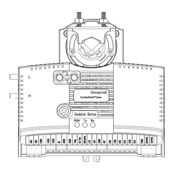
Page 6: Terminal Settings
TERMINAL SETTINGS Terminal Settings This section describes the terminal settings on the CPO-VAV2A controller. CPO-VAV2A Terminal Overview Figure 13 describes the layout of pins on the CPO-VAV2A controller. Declutch Button Figure 13 Describes the layout of pins on the CPO-VAV2A controller. LED operation Automatic MAC addressing Controllers with Automatic MAC addressing functionality can... -
Page 7: Manual Mac Addressing
TERMINAL SETTINGS address required. By default, the switches are already set to Scenario Time Remarks (0xFF) for controllers that support Automatic MAC addressing. C: Average time for MAC 50 secs 15 existing Auto MAC To enable Automatic MAC addressing again, set the switches conflicts to be resolved controllers. -
Page 8: Analog Input
TERMINAL SETTINGS There are two Hex switches on the controller: S1 and S2, as S1 Switch S2 Switch MAC Address shown in Figure 14. Attention Figure 14 CPO-VAV2A Hex Switches Layout Make sure that each CPO-VAV2A controller on the MS/TP bus has a unique MAC address. Valid Set S1 to the lower nibble of the address and S2 to the higher address for CPO-VAV2A is from 1 to 30. - Page 9 TERMINAL SETTINGS • CP-US-WM-VAV • CP-WM-VAV AGND CO2 Output 0...10V AGND Attention 24 VAC/DC Temp Terminals C7110D Resolution of the PT1000 sensor: 1 Fahrenheit or NTC 20kOhm Set Point Terminals 0.6 Centigrade. SETPT. 1...10kOhm ByPass/Fan Do not use the datapoint associated to PT1000 in LED INPUT control logic which requires a resolution less than OCCUPANCY...
-
Page 10: Analog Output
COMMUNICATION Analog Output • Support declutch mechanism to allow the installer to manually open or close the VAV box damper without power or software tool Analog outputs can be used, for example, to operate valve or • Shaft adapter: support different round (8 to 16 mm) or damper actuators. -
Page 11: Sylkbus
CONTROLLER STARTUP Sylk™ Bus Transformer requirements for one CPO- VAV2A controller The CPO-VAV2A controller has one Sylk port which is a two • Voltage: 24 VAC +/- 10% (50/60Hz) wire, polarity insensitive bus that provides both 24VAC power and communications between a Sylk-enabled sensor and a •... -
Page 12: Sylk Bus Cable Specification
CABLING Cable lengths and cross sectional areas Recommended maximum distance from controller to any Sylk device Signal type Cross-sectional Quantity Single twisted pair, non- Standard Less than or Less than or Less than or and type of shielded, stranded or solid thermostat wire, (non- equal to 300 Ft. - Page 13 CABLING MSTP Bus Connection 230 V 24 V CP-VAV/SPC/ CP-VAV/SPC/ CPO-VAV2A #1 CPO-VAV2A #N 90 to 510 Ω 510 Ω 120 Ohm RS485+ RS485- GND-ISO 5 V-ISO POWER BACnet/MSTP CP-IPC S24VAC N24VAC FGND NOTES: Always power the CP-IPC with a transformer separate to the connected BACnet MS/TP modules. N = max.
- Page 14 CABLING 230 V 24 V CP-VAV/SPC/ CP-VAV/SPC/ CPO-VAV2A #1 CPO-VAV2A #N 90 to 510 Ω 510 Ω 120 Ohm RS485+ RS485- DIP SWITCH ON GND-ISO 5 V-ISO CPO-PC-6A Connection (L > 3 m) of RS485 interfaces 1, 2, or 3 (RS485 interface 1 shown) to a BACnet Bus NOTES Always power the CPO-PC-6A with a transformer separate to the connected BACnet MS/TP modules.
- Page 15 CABLING MSTP Bus Connection 120 ohm 120 ohm FNGD FNGD CP-CORE CPO-VAV2A CPO-VAV2A ® Sylk Bus Connection CPO-VAV2A Sylk sensor 1 Sylk sensor N EN1B-0022 IE10 R0717...
- Page 16 CABLING Wiring Diagram of CPO-VAV2A DO for Integrated actuator CPO-VAV2A TRIAC EQUIVALENT CIRCUIT AIRFLOW PICKUP Shied should be continuous 24V AC MSTP Channel 24V AC COM Stage 1 Stage 2 Stage 3 T7560 Terminals Line Power Figure 25 Controller wiring diagram for typical VAV application -with Series Fan , staged Reheat, T7560 Wall Module DO for Integrated actuator CPO-VAV2A...
- Page 17 CABLING DO for Integrated actuator CPO-VAV2A TRIAC EQUIVALENT CIRCUIT AIRFLOW PICKUP Shied should be continuous 24V AC MSTP Channel 24V AC COM Sylk Bus Address Dial Modulating valve : 3 wires external CPO-TR40/42 powered 0...10V device Figure 27 Controller wiring diagram for typical VAV application - with modulating valves, CPO-TR40 and TR42 Wall Modules DO for Integrated actuator CPO-VAV2A...
-
Page 18: Connecting The Honeywell Bacnet Wi-Fi Adapter
Connecting the Honeywell BACnet Wi-Fi Adapter This section provides the connection drawings of CP-VAV/SPC controller with Honeywell BACnet Wi-Fi Adapter. For more details on Honeywell BACnet Wi-Fi Adapter, see the BACnet WiFi Adapter - Mounting and operating instructions (MU1B-0592GE51). BACnet MS/TP... -
Page 19: Federal Communications Commission (Fcc) Statement
Changes or modifications not expressly approved by the party responsible for compliance could void the user’s authority to operate the equipment. Honeywell Building Solutions 1985 Douglas Drive North Golden Valley MN 55422-4386 EN1B-0022 IE10 R0717 July 2017 www.honeywell.com © 2017 Honeywell International Inc.