Table of Contents
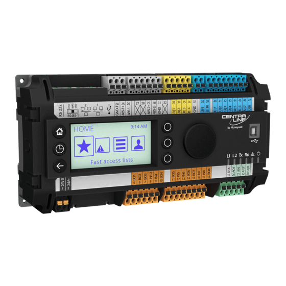
EAGLEHAWK NX Controller
TABLE OF CONTENTS
TABLE OF CONTENTS ......................................................... 1
Safety Information ................................................................ 2
General Safety Information ............................................... 2
Information as per EN 60730 ............................................ 2
WEEE Directive ................................................................ 2
Standards, Approvals, etc. ................................................ 2
3rd-Party Software Licenses ............................................... 2
Specifications of Controller ................................................. 3
System Overview .................................................................. 4
Overview of Hardware ...................................................... 4
System Architecture .......................................................... 5
Bus and Port Connections ................................................ 6
Set Up and Configuration .................................................. 12
General ........................................................................... 12
Procedure ....................................................................... 12
Configuring Ports to Enable Webserver Functions ......... 14
Firmware Update ............................................................ 15
Mounting/Dismounting ...................................................... 19
Before Installation ........................................................... 19
Dimensions ..................................................................... 19
Wiring and Set-Up .............................................................. 20
General Safety Considerations ....................................... 20
Lightning Protection ........................................................ 20
Wiring Terminals ............................................................. 20
Terminal Assignment ...................................................... 21
Power Supply .................................................................. 22
RIN-APU24 ..................................................................... 22
CLNXxxx26xxx Connection Examples ............................ 24
Internal I/Os of the EAGLEHAWK NX ............................. 26
Engineering, Commissioning ............................................ 29
Required Preparations .................................................... 29
Behavior of Outputs during Download ............................ 29
Extra Parts .......................................................................... 30
Software Licenses and Upgrades ..................................... 31
Panel Bus Connection ....................................................... 32
Overview of Panel Bus I/O Modules ............................... 32
Panel Bus Considerations ............................................... 32
a Panel Bus .................................................................... 33
® U.S. Registered Trademark
Copyright © 2018 Honeywell Inc. • All Rights Reserved
Installation &
Commissioning
Instructions
a Panel Bus .................................................................... 34
Addressing Panel Bus I/O Modules ................................ 35
Cable Specifications ....................................................... 35
Tuning Panel Bus Communication ................................. 36
Field Devices .................................................................. 38
LonWorks Communications ............................................. 39
General Information ....................................................... 39
BACnet MS/TP Bus Connection ....................................... 40
BACnet MS/TP Bus Considerations ............................... 40
a BACnet MS/TP Bus ..................................................... 40
a BACnet MS/TP Bus ..................................................... 42
Modbus Connection .......................................................... 43
Modbus Considerations .................................................. 43
a Modbus ....................................................................... 44
a Modbus ....................................................................... 45
M-Bus Connection ............................................................. 46
M-Bus Considerations .................................................... 46
M-Bus Connection Procedure ........................................ 47
Controller Performance ..................................................... 48
Troubleshooting ................................................................ 49
EAGLEHAWK NX Controller Troubleshooting ............... 49
Panel Bus I/O Module Troubleshooting .......................... 50
Appendix 1: Earth Grounding ........................................... 51
EAGLEHAWK NX Systems and SELV ........................... 51
Appendix 2 ......................................................................... 53
Sensor Input Accuracy ................................................... 53
Recognition of Sensor Failure of Sensor Inputs ............. 53
Sensor Characteristics ................................................... 53
Index ................................................................................... 56
Trademark Information
LON, L
W
, and Neuron are trademarks of Echelon
ON
ORKS
Corporation registered in the United States and other
countries.
Network .............................. 39
EN1Z-1039GE51 R1218
Table of Contents
Troubleshooting

Related Manuals for Honeywell CENTRA LINE EAGLEHAWK NX


Summary of Contents for Honeywell CENTRA LINE EAGLEHAWK NX
-
Page 1: Table Of Contents
, and Neuron are trademarks of Echelon ORKS Connecting EAGLEHAWK NX via its RS485-1 Interface to Corporation registered in the United States and other a Panel Bus ..............33 countries. ® U.S. Registered Trademark Copyright © 2018 Honeywell Inc. • All Rights Reserved EN1Z-1039GE51 R1218... -
Page 2: Safety Information
Device meets EN 60730-1, EN 60730-2-9, UL60730, and UL916. Use only accessory equipment which comes from or has ► been approved by Honeywell. Refer to Code of Practice standards IEC 61000-5-1 and -2 for guidance. Information as per EN 60730 The device complies with Ethernet Protocol versions IEEEC 802.3. -
Page 3: Specifications Of Controller
EAGLEHAWK NX CONTROLLER – INSTALLATION & COMMISSIONING INSTRUCTIONS SPECIFICATIONS OF CONTROLLER Table 2. EAGLEHAWK NX specifications 19 … 29 VAC, 50/60 Hz or Power supply 20 … 30 VDC typically DC: 7 W; max. 9 W Power consumption typically AC: 10 VA; max. 12 VA Max. -
Page 4: System Overview
EAGLEHAWK NX CONTROLLER – INSTALLATION & COMMISSIONING INSTRUCTIONS SYSTEM OVERVIEW Overview of Hardware Table 3. Overview of models (hardware) order no. without HMI with HMI max. feature description cable length NTC10kΩ / NTC20kΩ / 0…10 V / slow BI, 0.4 Hz 400 m NTC10kΩ... -
Page 5: System Architecture
EAGLEHAWK NX CONTROLLER – INSTALLATION & COMMISSIONING INSTRUCTIONS System Architecture An EAGLEHAWK NX System consists of the EAGLEHAWK NX controller and various Panel Bus I/O modules. The EAGLEHAWK NX controller provides interface connections, which allow connection to external systems (e.g., BACnet controllers). -
Page 6: Bus And Port Connections
EAGLEHAWK NX CONTROLLER – INSTALLATION & COMMISSIONING INSTRUCTIONS Bus and Port Connections 3 Two Ethernet / RJ45 sockets (for BACnet IP com- munication); 10/100 Mbit/s; 1 "link" LED + 1 "activity" Overview 4 USB 2.0 Host Interface (for connection of IF-LON2); max. - Page 7 EAGLEHAWK NX CONTROLLER – INSTALLATION & COMMISSIONING INSTRUCTIONS RS232 / RJ45 Socket Via its RS232 / RJ45 socket, the EAGLEHAWK NX controller can be connected (using an XW586 cable) to a PW M-Bus Adapter and thus to M-Bus networks. See also section "M- Bus Connection"...
- Page 8 EAGLEHAWK NX CONTROLLER – INSTALLATION & COMMISSIONING INSTRUCTIONS LEDs RIGHT (YELLOW) LED The EAGLEHAWK NX controller features the following LEDs: LIT CONTINUOUSLY = "100 Mbaud" DARK "10 Mbaud" L1 L2 Tx Rx INTER- INTER- FACE 1 FACE 2 LEFT (GREEN) LED Fig.
- Page 9 EAGLEHAWK NX CONTROLLER – INSTALLATION & COMMISSIONING INSTRUCTIONS 47 kOHM MID (DEFAULT) RS485-1 (+) RS485-1 (-) 47 kOHM GND-1 Fig. 14. RS485-1 three-position slide switch setting MID Fig. 12. Configuring the RS485 interfaces in COACH NX 550 OHM BIAS RS485-1 (+) RS485-1 Bias and Termination Resistors RS485-1 is equipped with a three-position slide switch which can be used to switch its bias resistors OFF (position "MID"...
- Page 10 EAGLEHAWK NX CONTROLLER – INSTALLATION & COMMISSIONING INSTRUCTIONS RS485-2 Bias and Termination Resistors Table 6. Bit rate vs. max. cable length for RS485 The RS485-2 interface is not affected by the aforementioned Bit rate Max. cable length (L) three-position slide switch. The 550Ω bias resistors and 130Ω 9.6 - 76.8 kbps 1200 m termination resistor of the RS485-2 are thus always ON.
- Page 11 – only once per Modbus connection. RS485 Repeaters RS485 repeaters are possible, but have not been tested by Honeywell. Hence it is within responsibility of the installing / commissioning person to ensure proper function. NOTE: Each Modbus segment will require its own line polarization and line termination.
-
Page 12: Set Up And Configuration
EAGLEHAWK NX CONTROLLER – INSTALLATION & COMMISSIONING INSTRUCTIONS SET UP AND CONFIGURATION General You can access the EAGLEHAWK NX controller via the RS232 interface using a terminal program (serial port) such as "PuTTY." This can be helpful in the following cases: •... - Page 13 EAGLEHAWK NX CONTROLLER – INSTALLATION & COMMISSIONING INSTRUCTIONS 5. Press 1 in the Main menu. RESULT: The Network Setup displays. FINISHED! 6. Configure the network as desired by applying the available options displayed. 7. To reset the controller to factory defaults, press F in the Boot menu.
-
Page 14: Configuring Ports To Enable Webserver Functions
EAGLEHAWK NX CONTROLLER – INSTALLATION & COMMISSIONING INSTRUCTIONS Configuring Ports to Enable Webserver 4. Click the Save button at the bottom. Functions RESULT: The changed port settings are saved. The EAGLEHAWK NX controller provides webserver func- tionality, e.g., for using the CentraLine N4 Supervisor. In order to use webserver functions, the http and https standard port settings must be changed as follows: •... -
Page 15: Firmware Update
EAGLEHAWK NX CONTROLLER – INSTALLATION & COMMISSIONING INSTRUCTIONS Firmware Update 1. Check the firmware version installed in your EAGLEHAWK NX as follows: Open COACH NX, go to the Platform/Platform Administration, and check the version of the Niagara Runtime installed in the EAGLEHAWK NX. -
Page 16
EAGLEHAWK NX CONTROLLER – INSTALLATION & COMMISSIONING INSTRUCTIONS 5. Double click the “Workbench User Home” link, you will be redirected to the user home 6. Navigate to
/sw/inbox folder. Resulting path for 4.4. is: C:\Users\ \Niagara4.4\tridium\sw\inbox 7. Copy and paste all four firmware files (contained in the firmware upgrade package) into the aforementioned inbox. 8. - Page 17 EAGLEHAWK NX CONTROLLER – INSTALLATION & COMMISSIONING INSTRUCTIONS 10. Connect to the EAGLEHAWK NX and start the Commissioning Wizard. 11. Deactivate all checkboxes; only Update Core Software needs to be selected. 12. Start the commissioning process. EN1Z-1039GE51 R1218...
- Page 18 EAGLEHAWK NX CONTROLLER – INSTALLATION & COMMISSIONING INSTRUCTIONS 13. After a successful update, the Platform Administration should show the new firmware version in the Niagara Runtime field: FINISHED! EN1Z-1039GE51 R1218...
-
Page 19: Mounting/Dismounting
EAGLEHAWK NX CONTROLLER – INSTALLATION & COMMISSIONING INSTRUCTIONS MOUNTING/DISMOUNTING Before Installation IMPORTANT To allow the evaporation of any condensation resulting from low shipping / storage temperatures, keep the controller at room temperature for at least 24 h before applying power. US requirement, only: This device must be installed in a UL-listed enclosure offering adequate space to maintain the segregation of line voltage field wiring and Class 2 field wiring. -
Page 20: Wiring And Set-Up
We recommend that the system be equipped with an external fuse. Fusing of Active Field Devices F2 (depends upon given load). Lightning Protection Please contact your local Honeywell representative for information on lightning protection. Wiring Terminals The EAGLEHAWK NX is equipped with push-in terminal plugs. -
Page 21: Terminal Assignment
EAGLEHAWK NX CONTROLLER – INSTALLATION & COMMISSIONING INSTRUCTIONS Terminal Assignment Table 8. Terminal assignment signal Description 24V-0 supply voltage (GND), int. connected with term. 31 and system GND (term. 19+37) 24V~ supply voltage (24V) not used Binary output 1. N.O. relay contact switching input power connected to terminal 8 Binary output 2. -
Page 22: Power Supply
EAGLEHAWK NX CONTROLLER – INSTALLATION & COMMISSIONING INSTRUCTIONS Power Supply Table 9. 1450 series transformers data part # Powering EAGLEHAWK NX primary side secondary side 1450 7287 Power is supplied via a removable terminal plug (attached to -001 120 VAC 24 VAC, 50 VA terminals 1 and 2). - Page 23 EAGLEHAWK NX CONTROLLER – INSTALLATION & COMMISSIONING INSTRUCTIONS Powering Field Devices and Panel Bus I/O Module via Separate Transformers • 24 V actuator connected to, e.g., an analog output module • Field device located 100 … 400 m from the analog output module 24 V0 230 VAC...
-
Page 24: Clnxxxx26Xxx Connection Examples
EAGLEHAWK NX CONTROLLER – INSTALLATION & COMMISSIONING INSTRUCTIONS CLNXxxx26xxx Connection Examples NTC20kOHM NTC20kOHM ACTIVE SENSOR TOTALIZER CONTACT SENSOR SENSOR 1: GND (24V 0) 1: GND 1: GND 1: GND 1: GND 2: 24V POWER 2: SIGNAL 2: SIGNAL 2: SIGNAL 2: SIGNAL 3: 0...10 VDC 24 25 26... - Page 25 EAGLEHAWK NX CONTROLLER – INSTALLATION & COMMISSIONING INSTRUCTIONS ACTIVE SENSOR 1: GND (24V 0) CONTACT 2: 24V POWER 1: GND 3: 0...10 VDC 2: SIGNAL A1 A2 A3 A4 A5 A6 A7 B1 B2 B3 B4 B5 B6 B7 XS830 1 2 3 4 5 6 7 1 2 3 4 5 6 7 24 25 26...
-
Page 26: Internal I/Os Of The Eaglehawk Nx
EAGLEHAWK NX CONTROLLER – INSTALLATION & COMMISSIONING INSTRUCTIONS Internal I/Os of the EAGLEHAWK NX 10 VDC The CLNXxxx00xxx is not equipped with inputs or outputs. The following sub-sections thus apply only to the 25 k CLNXxxx14xxx and CLNXxxx26xxx. Universal Inputs 200 k... - Page 27 EAGLEHAWK NX CONTROLLER – INSTALLATION & COMMISSIONING INSTRUCTIONS Analog Outputs Pulse Counter Specifications Using COACH NX, the binary inputs of the EAGLEHAWK NX The CLNXxxx26xxx is equipped with four (CLNXxxx14xxx: can be configured as pulse counters (fast totalizers) for two) analog outputs (AOs). operation in conjunction with devices equipped with an open In the event of an application stop (e.g., during application collector output.
- Page 28 EAGLEHAWK NX CONTROLLER – INSTALLATION & COMMISSIONING INSTRUCTIONS Binary Outputs The EAGLEHAWK NX features eight (CLNXxxx26xxx) or four (CLNXxxx14xxx) binary outputs arranged in two blocks (BO1…4 and BO5…8, respectively). WARNING Risk of electric shock or equipment damage! Low voltage and line voltage must not be wired within the same block.
-
Page 29: Engineering, Commissioning
EAGLEHAWK NX CONTROLLER – INSTALLATION & COMMISSIONING INSTRUCTIONS ENGINEERING, COMMISSIONING Option 2: Standard Ethernet Interface The default IP address of Ethernet interface 1 is: Please refer also to CentraLine NX BACnet Utilities Driver - 192.168.200.20 User Guide (Product Literature No.: EN2Z-1020GE51) for and the default IP address of Ethernet interface 2 is: detailed information. -
Page 30: Extra Parts
EAGLEHAWK NX CONTROLLER – INSTALLATION & COMMISSIONING INSTRUCTIONS EXTRA PARTS Table 18. Extra parts order no. description Set of ten terminals. Each package consists of two groups of nine internally connected push-in terminals, for distributing XS830 A1 A2 A3 A4 A5 A6 A7 A8 A9 B1 B2 B3 B4 B5 B6 B7 B8 B9 signals / power. -
Page 31: Software Licenses And Upgrades
+102 Panel Bus / onboard I/O points upgrade CLNXEHPB255UP +255 Panel Bus / onboard I/O points upgrade CLNXEHRBAC250UP +250 Honeywell BACnet points (for BACnet room devices, e.g., MERLIN / CPO-R) upgrade CLNXEHRLON250UP +250 Honeywell points (for L room devices, e.g., SERVAL / Excel 10) upgrade... -
Page 32: Panel Bus Connection
(with integrated electronic module) OUTPUT PANEL BUS I/O CLIOPR822A CLIOPR824A CLIOPR825A CLIOP830A ELECTRONIC MODULES Honeywell Binary Inputs Analog Inputs Analog Outputs 24V Relays AI6 AI7 CO1 CO2 CO3 CO4 CO5 CO6 AI2 AI3 NO1 NO2 NO3 NO4 NO5 NO6 Install. Instr. -
Page 33: Connecting Eaglehawk Nx Via Its Rs485-1 Interface To A Panel Bus
EAGLEHAWK NX CONTROLLER – INSTALLATION & COMMISSIONING INSTRUCTIONS Connecting EAGLEHAWK NX via its RS485-1 Interface to a Panel Bus NOTE: When connecting an EAGLEHAWK NX via its RS485-1 to a Panel Bus I/, it is recommended that the slide switch be set to "END."... -
Page 34: Connecting Eaglehawk Nx Via Its Rs485-2 Interface To A Panel Bus
EAGLEHAWK NX CONTROLLER – INSTALLATION & COMMISSIONING INSTRUCTIONS Connecting EAGLEHAWK NX via its RS485-2 Interface to a Panel Bus CentraLine I/O Module CentraLine I/O Module CentraLine I/O Module Com a Com a Com a Com b Com b Com b 24V~ 24V~ 24V~... -
Page 35: Addressing Panel Bus I/O Modules
EAGLEHAWK NX CONTROLLER – INSTALLATION & COMMISSIONING INSTRUCTIONS Table 20. Power supply cable specifications Addressing Panel Bus I/O Modules max. length 3 m (from transformer to final module) Each Panel Bus I/O Module must be addressed manually cross section min. 0.75 mm (AWG 18) using its HEX switch (S2). -
Page 36: Tuning Panel Bus Communication
EAGLEHAWK NX CONTROLLER – INSTALLATION & COMMISSIONING INSTRUCTIONS Tuning Panel Bus Communication The default polling interval for all Panel Bus points is set to "normal = 10s". Data from the field is thus updated every 10s. Write commands are sent without time delay. It is recommended that you update the polling interval of those points requiring more-frequent updating (see Fig. - Page 37 EAGLEHAWK NX CONTROLLER – INSTALLATION & COMMISSIONING INSTRUCTIONS You can assign different poll intervals to individual points in the Panel Bus Point Discovery Dialog (see Fig. 41). Fig. 41. Assigning different poll intervals to individual points in the Panel Bus Point Discovery Dialog EN1Z-1039GE51 R1218...
-
Page 38: Field Devices
EAGLEHAWK NX CONTROLLER – INSTALLATION & COMMISSIONING INSTRUCTIONS Field Devices Depending on the distance from the controller, field devices can be supplied with power by the same transformer used for the Panel Bus I/O Modules, or by a separate transformer, using cables as specified in Table 22. -
Page 39: Lonworks Communications
IV 22 AWG (Belden part number PARK POSITION 9H2201504) non-shielded, twisted-pair, solid-conductor (NO TERMINATION) wire. When possible, use Honeywell AK3781, AK3782, AK3791, or AK3792 cable (US part numbers). See Excel 50/5000 FTT/LPT BUS FTT/LPT FREE Mechanisms, EN0B-0270GE51, for details,... -
Page 40: Bacnet Ms/Tp Bus Connection
EAGLEHAWK NX CONTROLLER – INSTALLATION & COMMISSIONING INSTRUCTIONS BACNET MS/TP BUS CONNECTION The EAGLEHAWK NX controller features two RS485 interfaces to which BACnet MS/TP devices can be connected: RS485-1 (consisting of push-in terminals 24 [GND-1], 25, and 26) and/or RS485-2 (consisting of push-in terminals 29, 30, and 31 [GND- 2]). - Page 41 EAGLEHAWK NX CONTROLLER – INSTALLATION & COMMISSIONING INSTRUCTIONS Example 2: Multiple EAGLEHAWK NX Controllers and Connected BACnet Modules EAGLE- EAGLE- EAGLE- EAGLE- HAWK NX HAWK NX HAWK NX HAWK NX GND-1 GND-1 GND-1 GND-1 BACnet BACnet GND-1 GND-1 GND-1 GND-1 Module #2 Module #4 550 OHM...
-
Page 42: Connecting Eaglehawk Nx Via Its Rs485-2 Interface To A Bacnet Ms/Tp Bus
EAGLEHAWK NX CONTROLLER – INSTALLATION & COMMISSIONING INSTRUCTIONS Connecting EAGLEHAWK NX via its RS485-2 Interface to a BACnet MS/TP Bus With regards to Fig. 47 and Fig. 48, please note the following: NOTE: Always power each EAGLEHAWK NX controller and the connected BACnet MS/TP modules via separate transformers. NOTE: For "L,"... -
Page 43: Modbus Connection
EAGLEHAWK NX CONTROLLER – INSTALLATION & COMMISSIONING INSTRUCTIONS MODBUS CONNECTION The EAGLEHAWK NX controller supports both Modbus RTU master and Modbus RTU slave functionality. Modbus slaves can be connected to either or both of the two onboard RS485 interfaces: RS485-1 (consisting of push-in terminals 24 [GND-1], 25, and 26) or RS485-2 (consisting of push-in terminals 29, 30, 31 [GND-2]). -
Page 44: Connecting Eaglehawk Nx Via Its Rs485-1 Interface To A Modbus
EAGLEHAWK NX CONTROLLER – INSTALLATION & COMMISSIONING INSTRUCTIONS Connecting EAGLEHAWK NX via its RS485-1 Interface to a Modbus With regards to Fig. 49, please note the following: NOTE: Always power each EAGLEHAWK NX controller and the connected Modbus slaves via separate transformers. NOTE: For "L,"... -
Page 45: Connecting Eaglehawk Nx Via Its Rs485-2 Interface To A Modbus
EAGLEHAWK NX CONTROLLER – INSTALLATION & COMMISSIONING INSTRUCTIONS Connecting EAGLEHAWK NX via its RS485-2 Interface to a Modbus With regards to Fig. 50, please note the following: NOTE: Always power each EAGLEHAWK NX controller and the connected Modbus slaves via separate transformers. NOTE: For "L,"... -
Page 46: M-Bus Connection
˗ Maximum cable capacitance of 180 nF For bus length extension, M-Bus repeaters can be used, but have not been tested by Honeywell. Hence, it is the Not used responsibility of the installing / commissioning personnel to ensure proper functioning. -
Page 47: M-Bus Connection Procedure
EAGLEHAWK NX CONTROLLER – INSTALLATION & COMMISSIONING INSTRUCTIONS M-Bus Connection Procedure EAGLEHAWK NX Install the PW M-Bus Adapter on DIN rail. Insert a screwdriver into the slot in the DIN rail clamp on the underside of the PW and pry downward to loosen clamp until the unit snaps onto the rail. -
Page 48: Controller Performance
EAGLEHAWK NX CONTROLLER – INSTALLATION & COMMISSIONING INSTRUCTIONS CONTROLLER PERFORMANCE The controller performance has been tested in two test scenarios. NOTE: These are example scenarios. It is therefore, of course, possible for you to use any other mix of Panel Bus points and BACnet MS/TP points as long as the maximum number of hardware I/O points (see section "Panel Bus Considerations"... -
Page 49: Troubleshooting
EAGLEHAWK NX CONTROLLER – INSTALLATION & COMMISSIONING INSTRUCTIONS TROUBLESHOOTING EAGLEHAWK NX Controller Troubleshooting The following LEDs of the EAGLEHAWK NX controller can be used for troubleshooting purposes: • Power LED (green) • Status LED (red) • L1 and L2 LEDs (yellow) •... -
Page 50: Panel Bus I/O Module Troubleshooting
EAGLEHAWK NX CONTROLLER – INSTALLATION & COMMISSIONING INSTRUCTIONS L2 LED Table 31. EAGLEHAWK NX controller bus L2 LED case bus LED meaning remedy Platform has started / is reachable. ON con- No action necessary. tinuously after power-up Station is not running. Start station (enable auto start). -
Page 51: Appendix 1: Earth Grounding
If system protective earth grounding is planned, use a ► electrical impact. cable as short as possible for grounding: To support SELV, all Honeywell external (CRT series) or min. 1.5 mm² (16 AWG). internal transformers comply with standard EN60742. For connection details, refer to the following examples. - Page 52 EAGLEHAWK NX CONTROLLER – INSTALLATION & COMMISSIONING INSTRUCTIONS Example 2 When connecting multiple CPUs to a single transformer, it is imperative that the polarity of the power supply terminals of the CPUs and the polarity of the transformer always cor- respond (namely: 24V-0 of the transformer must always be connected to 24V-0 of the CPU, and 24V~ of the transformer must always be connected with 24V~ of the CPU).
-
Page 53: Sensor Input Accuracy
EAGLEHAWK NX CONTROLLER – INSTALLATION & COMMISSIONING INSTRUCTIONS APPENDIX 2 Sensor Input Accuracy The internal sensor inputs of the EAGLEHAWK NX controller support both NTC10kΩ and NTC20kΩ sensors (see also section "Universal Inputs" on page 26). The following table lists the typical minimum accuracies of the hardware and software for temperature sensors. - Page 54 EAGLEHAWK NX CONTROLLER – INSTALLATION & COMMISSIONING INSTRUCTIONS NTC 20 k (same voltages for inputs of Panel Bus I/O Modules and onboard inputs of EAGLEHAWK NX) Temp. Resistance Terminal Temp. Resistance Terminal Temp. Resistance Terminal Temp. Resistance Terminal [°C] [k voltage [V] [°C] [k...
- Page 55 EAGLEHAWK NX CONTROLLER – INSTALLATION & COMMISSIONING INSTRUCTIONS NTC10kΩ (same voltages for inputs of Panel Bus I/O Modules and onboard inputs of EAGLEHAWK NX) Temp. Resistance Terminal Temp. Resistance Terminal Temp. Resistance Terminal Temp. Resistance Terminal [°C] voltage [V] [°C] voltage [V] [°C] voltage [V]...
-
Page 56: Index
USB 2.0 Host Interface 6 via RS485-2 8, 41 details 7 Manufactured for and on behalf of the Connected Building Division of Honeywell Products and Solutions Sàrl, Z.A. La Pièce 16, 1180 Rolle, Switzerland by its Authorized Representative: CentraLine Honeywell GmbH Böblinger Strasse 17...