Honeywell CIPer 30 Installation Instructions Manual
Hide thumbs
Also See for CIPer 30:
- Installation instructions manual (13 pages) ,
- Installation and operation manual (41 pages)
Quick Links
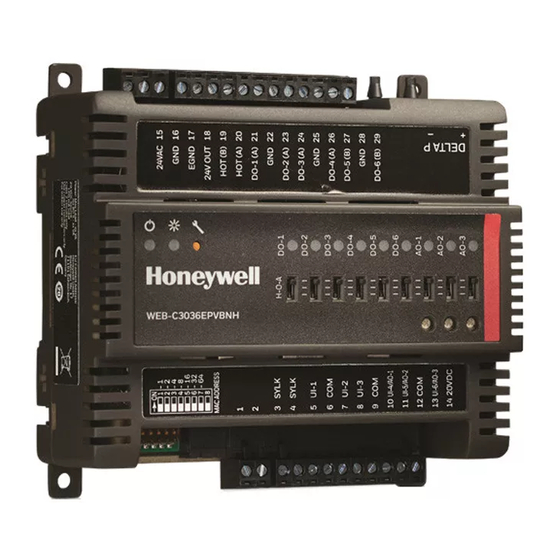
CIPer Model 30 Controller
Table 1
Parts and description
Model number
WEB-C3036EPUBNH Honeywell CIPer - IP controller with 3 universal inputs, 6 Binary Outputs, 3 Universal I/O and
WEB-C3036EPVBNH Honeywell CIPer - IP controller with 3 universal inputs, 6 Binary Outputs, 3 Universal I/O, VAV
WEB-O3022H
WEB-O9056H
Specifications:
Power consumption: AC: Max 100VA
Rated input voltage: 20-30 VAC; 50/60Hz
Impulse voltage: 330V
Ambient temperature: -4 to 131F (-20 to 55C)
Storage temperature: -4 to 150F (-20 to 65C)
Humidity: 5% to 95% non-condensing
Differential pressure sensor range (VAV model): 0-2"
WC (0 to 374 Pa) 32 to 122F (0 to 55C)
Universal Inputs / Analog Outputs (configurable): 6
UI / 3 configurable as AO
Flexible UI's to connect external sensors like
20KNTC, PT1000 and other resistive sensors
Digital Output type / rating: Solid-State Relay, 1.5A
Continuous, 3.5A inrush for 100 mS.
Digital Output voltage rating: 20 to 30 VAC @ 50/60
Hz
Pulse Inputs: 100Hz max, minimum duty cycle: 5 mS
ON / 5 mS OFF.
Purpose of Control: Operating Control, Open Energy
Management Equipment
Action: Type 1
Pollution degree: 2
ELV limits realized: 24V
© Honeywell
Description
HOA switches
airflow sensor and HOA switches
IO module with 3 universal inputs, 2 Binary Outputs, 2 Universal I/O and HOA switches
IO module with 9 universal inputs, 6 Binary Outputs, 5 Universal I/O and HOA switches
INSTALLATION INSTRUCTIONS
Introduction
The Honeywell CIPer Model 30 is a compact, Internet
Protocol (IP) edge controller for VAV, Unitary and Plant
applications. With its native Niagara N4 on-board
programming platform; the CIPer controller provides
Internet connectivity, Web serving capability, integrated
control, data logging, alarming, trending, and scheduling
management. The controller can be used to aggregate
information (including real-time data, alarms, trends,
and history) and integrate this data to the Sentience
Cloud for value-added data analytics.
Before Installation
WARNING! Install all equipment in accordance with the
National Electric Code and in a manner acceptable to the local
authority having jurisdiction. Read these instructions and the
CIPer Model 30 controller Installation Instructions (31-00183-
01) carefully before installing equipment. Failure to follow all
instructions may result in equipment damage or a hazardous
condition.
Attention! Installez tout le matériel en conformité avec le
Code national de l'électricité et d'une manière acceptable pour
l'autorité localecompétente. Lisez ces instructions et le guide d'
installation et fonctionnement de l'ACM (LT-ACMIOG) avant
l'installation du matériel. Le non respect des instructions peut
entraîner desdes dommages matériels ou une situation
dangereuse.
WARNING! The CIPer 30 controller and its components may
be
susceptible
to
appropriate ESD grounding techniques while handling the
product. When possible, always handle the product by its non-
electrical components.
Page 1
electrostatic
discharge
31-00183-02
(ESD).
Use

Related Manuals for Honeywell CIPer 30


Summary of Contents for Honeywell CIPer 30
- Page 1 Parts and description Model number Description WEB-C3036EPUBNH Honeywell CIPer - IP controller with 3 universal inputs, 6 Binary Outputs, 3 Universal I/O and HOA switches WEB-C3036EPVBNH Honeywell CIPer - IP controller with 3 universal inputs, 6 Binary Outputs, 3 Universal I/O, VAV...
-
Page 2: Installation
The CIPer 30 controller is available in two models (See table 1). Review the power, input, and output specifications before installing the controller. Installation The CIPer Model 30 controller must be mounted in a position that allows clearance for wiring, servicing, removal, connection of the terminal blocks and access to the MAC address DIP switches. -
Page 3: Using Terminal Blocks
Hold the cable in place and turn the adjustment screw clockwise to tighten it until the clamps in the wire slot secure the cable. Tug gently on the cable to ensure that it’s securely terminated 31-00183-02 © Honeywell Page 3... - Page 4 Both type of I/O modules WEB-O3022H and WEB-O9056H can be connected directly to the WEB- C3036EPVBNH controller as shown in Fig. 3. Fig. 3 Stacked Controller and IO modules Fig. 4 Remotely mounted expansion module 31-00183-02 © Honeywell Printed in USA...
-
Page 5: Ethernet Connections
L'exploitation est autorisée aux deux conditions suivantes: (1) l'appareil ne doit pas produire de brouillage, et (2) l'utilisateur de l'appareil doit accepter tout brouillage radioélectrique subi, même si le brouillage est susceptible d'en compromettre le 31-00183-02 © Honeywell Page 5... - Page 6 Augmenter l’espace entre l’appareil et le récepteur. Brancher l’appareil à une prise de courant différente de celle sur laquelle le récepteur est branché. Pour obtenir de l’aide, contacter le vendeur ou un technicien radio/télévision expérimenté. 31-00183-02 © Honeywell Printed in USA...
- Page 7 Honeywell Building Technologies Honeywell International Inc. 1985 Douglas Drive North ® U.S. Registered Trademark Golden Valley, MN 55422 © 2019Honeywell International Inc. 31-00183-02 customer.honeywell.com...