Table of Contents
EAGLEHAWK Controller
Safety Information ................................................................ 2
General Safety Information ............................................... 2
Information as per EN 60730 ............................................ 2
WEEE Directive ................................................................ 2
Standards, Approvals, etc. ................................................ 2
3rd-Party Software Licenses ............................................... 2
Specifications of Controller ................................................. 3
System Overview .................................................................. 3
Overview of Hardware ...................................................... 3
System Architecture .......................................................... 4
Bus and Port Connections ................................................ 5
Mounting/Dismounting ...................................................... 10
Before Installation ........................................................... 10
Dimensions ..................................................................... 10
Wiring and Set-Up .............................................................. 11
General Safety Considerations ....................................... 11
Wiring Terminals ............................................................. 11
Terminal Assignment ...................................................... 11
Power Supply .................................................................. 11
RIN-APU24 ..................................................................... 12
Lightning Protection ........................................................ 12
Engineering, Commissioning ............................................ 13
Required Preparations .................................................... 13
Behavior of Outputs during Download ............................ 13
Extra Parts .......................................................................... 14
Software Licenses and Upgrades ..................................... 14
Panel Bus Connection ....................................................... 15
Overview of Panel Bus I/O Modules ............................... 15
Panel Bus Considerations ............................................... 15
Panel Bus ....................................................................... 16
Panel Bus ....................................................................... 17
Cable Specifications ....................................................... 18
® U.S. Registered Trademark
Copyright © 2016 Honeywell Inc. • All Rights Reserved
Installation &
Commissioning
Instructions
TABLE OF CONTENTS
LonWorks Communications ............................................. 19
General Information ....................................................... 19
BACnet MS/TP Bus Connection ....................................... 20
BACnet MS/TP Bus Considerations ............................... 20
BACnet MS/TP Bus ........................................................ 20
BACnet MS/TP Bus ........................................................ 22
Modbus Connection .......................................................... 23
Modbus Considerations .................................................. 23
Modbus .......................................................................... 23
Modbus .......................................................................... 24
M-Bus Connection ............................................................. 25
M-Bus Considerations .................................................... 25
M-Bus Connection Procedure ........................................ 26
Troubleshooting ................................................................ 28
EAGLEHAWK Controller Troubleshooting ..................... 28
Panel Bus I/O Module Troubleshooting .......................... 29
Appendix 1: Earth Grounding ........................................... 30
EAGLEHAWK Systems and SELV ................................. 30
EAGLEHAWK Systems and Standard EN60204-1 ........ 30
Index ................................................................................... 32
Trademark Information
LON, L
W
ON
ORKS
Corporation registered in the United States and other
countries.
Network .............................. 19
, and Neuron are trademarks of Echelon
EN1Z-1005GE51 R0216
Table of Contents
Troubleshooting

Related Manuals for Honeywell CENTRA LINE EAGLEHAWK


Summary of Contents for Honeywell CENTRA LINE EAGLEHAWK
-
Page 1: Table Of Contents
Corporation registered in the United States and other Panel Bus ............... 16 countries. Connecting EAGLEHAWK via its RS485-2 Interface to a Panel Bus ............... 17 Cable Specifications ............18 ® U.S. Registered Trademark Copyright © 2016 Honeywell Inc. • All Rights Reserved EN1Z-1005GE51 R0216... -
Page 2: Safety Information
Device meets EN 60730-1, EN 60730-2-9, UL60730, and Use only accessory equipment which comes from or has ► UL916. been approved by Honeywell. Refer to Code of Practice standards IEC 61000-5-1 and -2 for guidance. Information as per EN 60730... -
Page 3: Specifications Of Controller
EAGLEHAWK CONTROLLER – INSTALLATION & COMMISSIONING INSTRUCTIONS SPECIFICATIONS OF CONTROLLER Table 2. EAGLEHAWK specifications 19 … 29 VAC, 50/60 Hz or Power supply 20 … 30 VDC typically dc: 5 W; max. 6 W Power consumption typically ac: 9 VA; max. 11 VA typically dc: 210 mA;... -
Page 4: System Architecture
EAGLEHAWK CONTROLLER – INSTALLATION & COMMISSIONING INSTRUCTIONS System Architecture An EAGLEHAWK System consists of the EAGLEHAWK controller and various Panel Bus I/O modules. The EAGLEHAWK controller provides interface connections, which allow connection to external systems (e.g., BACnet controllers). Via the IF-LON External Interface, the EAGLEHAWK can also communicate with L systems, including CentraLine L ORKS... -
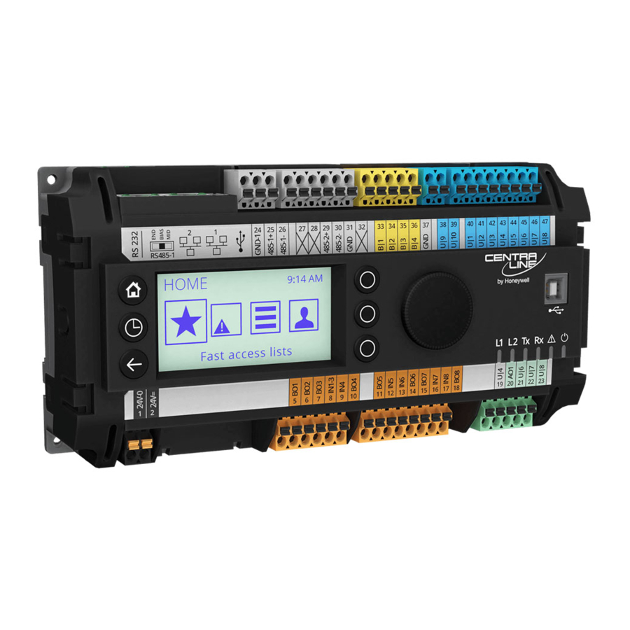
Page 5: Bus And Port Connections
EAGLEHAWK CONTROLLER – INSTALLATION & COMMISSIONING INSTRUCTIONS Bus and Port Connections 5 RS485-2* (non-isolated; for BACnet MS/TP, Panel Bus, or Modbus RTU communication) Overview 6 LEDs 7 USB 2.0 Device Interface (for connection to COACH web browsers, and 3 -party touch panels) WARNING 8 Three-position slide switch (for setting bias and termination resistance of RS485-1) - Page 6 EAGLEHAWK CONTROLLER – INSTALLATION & COMMISSIONING INSTRUCTIONS USB 2.0 Host Interface Ethernet / RJ45 socket Fig. 5. USB 2.0 Host interface Fig. 7. Ethernet / RJ45 socket USB 2.0 Device Interface This Ethernet / RJ45 socket is a 10/100-Mbaud Ethernet interface permitting communication (as per IEEEC 802.3) on All models of the EAGLEHAWK controller are equipped with a any supported IP network, e.g.: BACnet (IP), FOX, etc.
- Page 7 EAGLEHAWK CONTROLLER – INSTALLATION & COMMISSIONING INSTRUCTIONS RS485 Interfaces General 47 kOHM The EAGLEHAWK controller features two RS485 interfaces: MID (DEFAULT) RS485-1 (consisting of push-in terminals 24 [GND-1], 25, RS485-1 (+) and 26) is isolated and can be used for any RS485-based communication protocol available within Niagara Ecosystems, e.g.: Panel Bus, BACnet MS/TP, etc.
- Page 8 EAGLEHAWK CONTROLLER – INSTALLATION & COMMISSIONING INSTRUCTIONS RS485-2 Bias and Termination Resistors Table 6. Baud rate vs. max. cable length for RS485 The RS485-2 interface is not affected by the aforementioned Baud rate Max. cable length (L) three-position slide switch. The 550Ω bias resistors and 130Ω 9.6 - 76.8 kbps 1200 m termination resistor of the RS485-2 are thus always ON.
- Page 9 – only once per Modbus connection. RS485 Repeaters RS485 repeaters are possible, but have not been tested by Honeywell. Hence it is within responsibility of the installing/commissioning person to ensure proper function. NOTE: Each Modbus segment will require its own line polarization and line termination.
-
Page 10: Mounting/Dismounting
EAGLEHAWK CONTROLLER – INSTALLATION & COMMISSIONING INSTRUCTIONS MOUNTING/DISMOUNTING Before Installation IMPORTANT To allow the evaporation of any condensation resulting from low shipping / storage temperatures, keep the controller at room temperature for at least 24 h before applying power. US requirement, only: This device must be installed in a UL-listed enclosure offering adequate space to maintain the segregation of line voltage field wiring and Class 2 field wiring. -
Page 11: Wiring And Set-Up
EAGLEHAWK CONTROLLER – INSTALLATION & COMMISSIONING INSTRUCTIONS WIRING AND SET-UP General Safety Considerations All wiring must comply with applicable electrical codes and ordinances, including VDE, National Electric Code (NEC) or equivalent, and any local regulations must be observed. Refer to job or manufacturer’s drawings for details. Local wiring guidelines (e.g., IEC 364-6-61 or VDE 0100) may take precedence over recommendations provided here. -
Page 12: Rin-Apu24
500 mA CRT 6 230 Vac 1300 mA Lightning Protection CRT 12 230 Vac 12 A 2500 mA Please contact your local Honeywell representative for information on lightning protection. PRIMARY SIDE EAGLEHAWK 230 VAC 24 VAC 24 V0 120 VAC RECOMMENDED Fig. -
Page 13: Engineering, Commissioning
EAGLEHAWK CONTROLLER – INSTALLATION & COMMISSIONING INSTRUCTIONS ENGINEERING, COMMISSIONING Option 2: Standard Ethernet Interface The standard IP address can be set in COACH . For this Required Preparations purpose, connect first with the USB interface. In any case, In order to access (with a laptop or PC) the EAGLEHAWK your PC's IP address must match the EAGLEHAWK controller via Ethernet/IP for the first time, you may employ controller's default IP address subnet. -
Page 14: Extra Parts
100 Panel Bus points) CLAXEH3PTY25UP (EAGLEHAWK upgrade license for an additional 25 integrated points) CLAXDEMOEH (EAGLEHAWK demo license) unlimited NOTE: The maximum permitted number of Honeywell Panel Bus points is 400. The maximum recommended number of integrated points is 400. EN1Z-1005GE51 R0216... -
Page 15: Panel Bus Connection
PANEL BUS I/O CLIOPR822A CLIOPR824A CLIOPR825A CLIOP830A ELECTRONIC MODULES Honeywell Binary Inputs Analog Inputs Analog Outputs 24V Relays CO1 CO2 CO3 CO4 CO5 CO6 NO1 NO2 NO3 NO4 NO5 NO6 1 2 3 4 5 6 7 8 9 10 11 12 1 2 3 4 5 6 Install. -
Page 16: Connecting Eaglehawk Via Its Rs485-1 Interface To A Panel Bus
EAGLEHAWK CONTROLLER – INSTALLATION & COMMISSIONING INSTRUCTIONS Connecting EAGLEHAWK via its RS485-1 Interface to a Panel Bus NOTE: When connecting an EAGLEHAWK via its RS485-1 to a Panel Bus I/, it is recommended that the slide switch be set to “END.” CentraLine I/O Module CentraLine I/O Module CentraLine I/O Module... -
Page 17: Connecting Eaglehawk Via Its Rs485-2 Interface To A Panel Bus
EAGLEHAWK CONTROLLER – INSTALLATION & COMMISSIONING INSTRUCTIONS Connecting EAGLEHAWK via its RS485-2 Interface to a Panel Bus CentraLine I/O Module CentraLine I/O Module CentraLine I/O Module Com a Com a Com a Com b Com b Com b EAGLEHAWK 24V~ 24V~ 24V~ 24~0... -
Page 18: Cable Specifications
EAGLEHAWK CONTROLLER – INSTALLATION & COMMISSIONING INSTRUCTIONS Cable Specifications Field Devices Depending on the distance from the controller, field devices Panel Bus I/O Modules can be supplied with power by the same transformer used for When checking the length of the power supply cable, the the Panel Bus I/O Modules, or by a separate transformer, connection cables to all Panel Bus I/O Modules must be using cables as specified in Table 16. -
Page 19: Lonworks Communications
Fig. 31. L connection and termination module ORKS 9H2201504) non-shielded, twisted-pair, solid-conductor wire. When possible, use Honeywell AK3781, AK3782, AK3791, or AK3792 cable (US part numbers). See Excel 50/5000 Mechanisms, EN0B-0270GE51, for details, ORKS including maximum lengths. Use wire with a minimum size of 20 AWG (0.5 mm ) and a maximum size of 14 AWG (2.5 mm... -
Page 20: Bacnet Ms/Tp Bus Connection
EAGLEHAWK CONTROLLER – INSTALLATION & COMMISSIONING INSTRUCTIONS BACNET MS/TP BUS CONNECTION The EAGLEHAWK controller features two RS485 interfaces to which BACnet MS/TP devices can be connected: RS485-1 (consisting of push-in terminals 24 [GND-1], 25, and 26) and/or RS485-2 (consisting of push-in terminals 29, 30, and 31 [GND- 2]). - Page 21 EAGLEHAWK CONTROLLER – INSTALLATION & COMMISSIONING INSTRUCTIONS Example 2: Multiple EAGLEHAWK Controllers and Connected BACnet Modules EAGLEHAWK EAGLEHAWK EAGLEHAWK EAGLEHAWK GND-1 GND-1 GND-1 GND-1 BACnet BACnet GND-1 GND-1 GND-1 GND-1 Module #2 Module #4 550 OHM 150 OHM 550 OHM 47 kOHM 47 kOHM 47 kOHM...
-
Page 22: Connecting Eaglehawk Via Its Rs485-2 Interface To A Bacnet Ms/Tp Bus
EAGLEHAWK CONTROLLER – INSTALLATION & COMMISSIONING INSTRUCTIONS Connecting EAGLEHAWK via its RS485-2 Interface to a BACnet MS/TP Bus With regards to Fig. 35 and Fig. 36, please note the following: NOTE: Always power each EAGLEHAWK controller and the connected BACnet MS/TP modules via separate transformers. NOTE: For “L,”... -
Page 23: Modbus Connection
EAGLEHAWK CONTROLLER – INSTALLATION & COMMISSIONING INSTRUCTIONS MODBUS CONNECTION The EAGLEHAWK controller supports both Modbus RTU master and Modbus RTU slave functionality. Modbus slaves can be connected to either or both of the two onboard RS485 interfaces: RS485-1 (consisting of push-in terminals 24 [GND-1], 25, and 26) or RS485-2 (consisting of push-in terminals 29, 30, 31 [GND-2]). -
Page 24: Connecting Eaglehawk Via Its Rs485-2 Interface To A Modbus
EAGLEHAWK CONTROLLER – INSTALLATION & COMMISSIONING INSTRUCTIONS Connecting EAGLEHAWK via its RS485-2 Interface to a Modbus With regards to Fig. 38, please note the following: NOTE: Always power each EAGLEHAWK controller and the connected Modbus slaves via separate transformers. NOTE: For “L,”... -
Page 25: M-Bus Connection
˗ Maximum cable capacitance of 180 nF For bus length extension, M-Bus repeaters can be used, but have not been tested by Honeywell. Hence, it is the Not used responsibility of the installing / commissioning personnel to ensure proper functioning. -
Page 26: M-Bus Connection Procedure
EAGLEHAWK CONTROLLER – INSTALLATION & COMMISSIONING INSTRUCTIONS M-Bus Connection Procedure EAGLEHAWK Install the PW M-Bus Adapter on DIN rail. Insert a screwdriver into the slot in the DIN rail clamp on the underside of the PW and pry downward to loosen clamp until the unit snaps onto the rail. -
Page 27: Effect Of Poll Rate + Subscribed Points On Cpu Load
EAGLEHAWK CONTROLLER – INSTALLATION & COMMISSIONING INSTRUCTIONS EFFECT OF POLL RATE + SUBSCRIBED POINTS ON CPU LOAD The poll rate set for the EAGLEHAWK and the chosen number of subscribed points both make a demand on the CPU load. The EAGLEHAWK has been verified to support the following scenario. -
Page 28: Troubleshooting
EAGLEHAWK CONTROLLER – INSTALLATION & COMMISSIONING INSTRUCTIONS TROUBLESHOOTING EAGLEHAWK Controller Troubleshooting The following LEDs of the EAGLEHAWK controller can be used for troubleshooting purposes: Power LED (green) Status LED (red) L1 and L2 LEDs (yellow) Tx (sending data on RS485-1) and Rx (receiving data on RS485-1) LEDs Power LED (green) of EAGLEHAWK Table 21. -
Page 29: Panel Bus I/O Module Troubleshooting
EAGLEHAWK CONTROLLER – INSTALLATION & COMMISSIONING INSTRUCTIONS Tx and Rx LEDs Table 25. EAGLEHAWK controller bus LEDs Tx and Rx case bus LEDs meaning remedy Normal operation; RS485-1 is functioning Both Tx and Rx No action necessary properly. are flashing No communication on RS485-1. -
Page 30: Appendix 1: Earth Grounding
If system protective earth grounding is planned, use a ► cable as short as possible for grounding: To support SELV, all Honeywell external (CRT series) or min. 1.5 mm² (16 AWG). internal transformers comply with standard EN60742. Earth grounding is therefore not recommended. - Page 31 EAGLEHAWK CONTROLLER – INSTALLATION & COMMISSIONING INSTRUCTIONS Example 2 When connecting multiple CPUs to a single transformer, it is imperative that the polarity of the power supply terminals of the CPUs and the polarity of the transformer always cor- respond (namely: 24V-0 of the transformer must always be connected to 24V-0 of the CPU, and 24V~ of the transformer must always be connected with 24V~ of the CPU).
-
Page 32: Index
13 status LED 6 troubleshooting 28 Manufactured for and on behalf of the Environmental and Combustion Controls Division of Honeywell Technologies Sàrl, Rolle, Z.A. La Pièce 16, Switzerland by its Authorized Representative: CentraLine Honeywell GmbH Böblinger Strasse 17 71101 Schönaich, Germany...