
Related Manuals for Honeywell ComfortPoint Open CPO-PC400-W


Summary of Contents for Honeywell ComfortPoint Open CPO-PC400-W
- Page 1 ™ ComfortPoint Open CPO-PC400-W/CPO-PC400-UW HVAC CONTROLLER INSTALLATION INSTRUCTIONS...
-
Page 2: Table Of Contents
CPO-PC400-W/CPO-PC400-UW HVAC CONTROLLER CONTENTS Wiring Terminals ................13 General Safety Information ..........3 Connecting Power Supply ............13 Earth Grounding ................13 Technical Data ............... 4 Cable Specifications ..............14 Electrical Data ................4 Power Consumption ..............4 Wireless Connectivity ............15 Current Consumption ..............4 Connectivity Frequency Range ..........15 Operational Environment ............ -
Page 3: General Safety Information
• Use only accessory equipment which comes from or has The CPO-PC400-W/CPO-PC400-UW is used for the been approved by Honeywell. purpose of building HVAC control and is suitable for use • It is recommended that devices be kept at room only in non-safety controls for installation on or in temperature for at least 24 hours before applying power. -
Page 4: Technical Data
CPO-PC400-W/CPO-PC400-UW HVAC CONTROLLER TECHNICAL DATA Table 5. CPO-PC400-W/CPO-PC400-UW Operational Environment Electrical Data Ambient Storage -28.9 to +70°C (-20 to 158 °F) Temperature Table 2. CPO-PC400-W/CPO-PC400-UW Electrical Data Ambient Storage 5 to 95% relative humidity Humidity (non-condensing) Operating Voltage 19 to 29 Vac (50/60Hz) (AC) Vibration Under 0.024”... -
Page 5: Interfaces
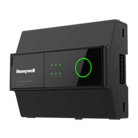
CPO-PC400-W/CPO-PC400-UW HVAC CONTROLLER INTERFACES The CPO-PC400-W/CPO-PC400-UW can communicate with a wide range of devices and systems with its interfaces and is configurable for a variety of protocols. Fig. 1. CPO-PC400-W/CPO-PC400-UW Controller Table 8. Controller Terminals (Continued) Table 8. Controller Terminals Type Legend Signal... -
Page 6: Tx Leds And Rx Leds
CPO-PC400-W/CPO-PC400-UW HVAC CONTROLLER Tx LEDs and Rx LEDs Table 8. Controller Terminals (Continued) The CPO-PC400-W/CPO-PC400-UW is equipped with Type Legend Signal Comment three Tx LEDs and three corresponding Rx LEDs. These LEDs indicate the transmission and reception of data by Ethernet 1 the three RS485 interfaces. -
Page 7: General Information On The Rs485 Standard
CPO-PC400-W/CPO-PC400-UW HVAC CONTROLLER General Information on the RS485 Ethernet Interfaces and LEDs Standard The two Ethernet interfaces 1 and 2 are internally connected to a single Ethernet switch. According to the RS485 standard (TIA/EIA-485: “Electrical Characteristics of Generators and Receivers for Use in Both Ethernet 1 and 2 can connect the controller with Balanced Digital Multipoint Systems”), only one driver laptop/PC using Ethernet crossover cable. -
Page 8: Connection To Buses
CPO-PC400-W/CPO-PC400-UW HVAC CONTROLLER Connection to Buses Communication Baud Rates Table 12. Connection to Buses Table 13. Communication Baud Rates Ethernet 10/100 Mbit/s, RJ45 Max. No. of Protocols Devices per BACnet MSTP 9.6, 19.2, 38.4, 76.8, 115.2 Kbps Channel Modbus 0.3 to 115.2 Kbps Panel Bus Panel Bus 115.2 Kbps... -
Page 9: Connection To Bacnet Mstp Bus
CPO-PC400-W/CPO-PC400-UW HVAC CONTROLLER Connection to Field Buses Table 14. Panel I/O modules The CPO-PC400-W/CPO-PC400-UW can communicate with ComfortPoint Open Field Bus Adapters. There are four ComfortPoint Open Field Bus Adapters to Descripti choose from (see Table 15 on page 9). Name XF824 Pluggable... -
Page 10: Connection To Cp-Io Bus
— Max. cable capacitance of 180 nF. For bus length extension, M-Bus repeaters can be used, but have not been tested by Honeywell. Hence, it is the responsibility of the installing / commissioning personnel to ensure proper functioning. Wiring Topology M-Bus meters are connected to the bus cable in parallel. -
Page 11: Power Supply
Description 6. In the U.S.A. and Canada, NEC Class-2 trans- formers must be used. 4 A, time-lag fuse (slo-blow), e.g., Littlefuse type 218.004. Table 16. Honeywell CRT Series Transformers (Europe) Depends upon field devices. Part No. Primary Side Secondary Side F3 (Field Bus, 8 A, time-lag fuse. - Page 12 CPO-PC400-W/CPO-PC400-UW HVAC CONTROLLER Example 1: Power Supply via Controller Using Panel Module • 24 V actuator connected to an analog output module • Actuator less than 100 m away from the controller. XF822 or XFR822 ACTUATOR CPO-PC400-W/ CPO-PC400-UW 24V~ 24V~ 110VAC/230VAC 24VAC 1 ……...
-
Page 13: Wiring And Set-Up
CPO-PC400-W/CPO-PC400-UW HVAC CONTROLLER WIRING AND SET-UP Table 20. RS485 Interface 4 Wiring Terminals Specifica- tions General Safety Considerations Terminal Torque Stripping Max. Plug Gauge Length Type Value • When connecting the CPO-PC400-W/CPO-PC400-UW, VDE, National Electric Code (NEC) or equivalent, and Screw 5 to 7 Cable without... -
Page 14: Cable Specifications
CPO-PC400-W/CPO-PC400-UW HVAC CONTROLLER Cable Specifications Field Device Power Supply Cable Specifications Power Supply Cable Specifications Table 24. Field Device Power Supply (24 Vac) Cable The length of the power supply cable includes the length of Specifications the cables to connected modules. Cable Length Cable Cross-section NOTE: The supply voltage must, in any case, be at least... -
Page 15: Wireless Connectivity
CPO-PC400-W/CPO-PC400-UW HVAC CONTROLLER WIRELESS CONNECTIVITY • This device complies with FCC radiation exposure limits set forth for an uncontrolled environment. Connectivity Frequency Range • This device must not be co-located or operating in conjunction with any other antenna or transmitter. Table 26. - Page 16 CPO-PC400-W/CPO-PC400-UW HVAC CONTROLLER EN0B-0085 IE10 R0420...
-
Page 17: Automatic Resetting Fuse
CPO-PC400-W/CPO-PC400-UW HVAC CONTROLLER AUTOMATIC RESETTING FUSE The 24V~ and 24V0 terminals at RS485-4 Interface have an automatic resetting fuse protection. The table below provides a maximum quantity of each IO module type that can be powered from the 24V~ and 24V0 terminals at RS485-4 Interface. If a mixture of IO modules is to be installed, use the table as a guide to determine if the IO modules can be powered from the 24V~ and 24V0 terminals at RS485-4 Interface or if a separate power source needs to be used. -
Page 18: Connection Examples
CPO-PC400-W/CPO-PC400-UW HVAC CONTROLLER CONNECTION EXAMPLES Connection to Panel Bus I/O Modules Powered by a Separate Transformer This configuration has the advantage of allowing the CPO-PC400-W/CPO-PC400-UW and the Panel Bus I/O modules to be installed in (several) different wiring cabinets – as long as the max. permissible length of A + C ≤ 3 m is maintained. This same configuration can also be extended, with multiple transformers powering Panel Bus I/O modules installed in multiple wiring cabinets for a total of max. - Page 19 CPO-PC400-W/CPO-PC400-UW HVAC CONTROLLER CONNECTION VIA RS485 INTERFACE 4 110VAC/230VAC L > 3m 24VAC CPO-PC400-W/CPO-PC400-UW Panel Bus Panel Bus I/O Module #1 I/O Module #N Isola on FGND Barrier GND_ISO RS485- RS485+ 24VAC 5V_ISO A+C = MAX.30 Meters 110VAC/230VAC Fig. 10. Connection (L > 3 m) of RS485 interface 4 to a Panel Bus NOTES: —...
- Page 20 CPO-PC400-W/CPO-PC400-UW HVAC CONTROLLER Connection to Panel Bus I/O Modules Powered by the Same Transformer as the CPO- PC400-W/CPO-PC400-UW This configuration is suitable for connecting Panel I/O modules which are all located in the same wiring cabinet as the CPO-PC400-W/CPO-PC400-UW. CONNECTION VIA RS485 INTERFACES 1, 2, OR 3 L <...
- Page 21 CPO-PC400-W/CPO-PC400-UW HVAC CONTROLLER CONNECTION VIA RS485 INTERFACE 4 110VAC/230VAC 24VAC CPO-PC400-W/CPO-PC400-UW Panel Bus Panel Bus I/O Module #1 I/O Module #N Isola on FGND Barrier GND_ISO RS485- RS485+ A+C = MAX.3 Meters 5V_ISO Fig. 12. Connection (A + C < 3 m) of RS485 interface 4 to a Panel Bus NOTES: —...
- Page 22 CPO-PC400-W/CPO-PC400-UW HVAC CONTROLLER Connection to BACnet MSTP Buses with Isolated Transceivers L > 3m CP-VAV/SPC #1 CP-VAV/SPC #N 110VAC/230VAC 24VAC 5V_ISO GND_ISO Isola on Barrier CPO-PC400-W/CPO-PC400-UW Fig. 13. Connection (L > 3 m) of RS485 interfaces 1, 2, or 3 (RS485 interface 1 shown) to a BACnet Bus NOTES: —...
- Page 23 CPO-PC400-W/CPO-PC400-UW HVAC CONTROLLER Recommended connection for BACnet MSTPMSTP Buses with non-isolated RS485 Interfaces L > 3m 110VAC/230VAC 24VAC GND_ISO 5V_ISO Isola on Barrier CPO-PC400/CPO-PC400-W/ CPO-PC400-UW Fig. 14. Connection (L > 3 m) of RS485 interfaces 1, 2, or 3 (RS485 interface 1 shown) to a BACnet Bus NOTES: —...
- Page 24 CPO-PC400-W/CPO-PC400-UW HVAC CONTROLLER Connection to C-Bus channel L > 3m XL500 #1 XL500 #N 110VAC/230VAC 24VAC 5V_ISO Isola on Barrier CPO-PC400-W/CPO-PC400-UW Fig. 15. Connection (L > 3 m) of RS485 interfaces 1, 2, or 3 (RS485 interface 1 shown) to a C-Bus NOTES: —...
- Page 25 CPO-PC400-W/CPO-PC400-UW HVAC CONTROLLER Connection to Field Bus Modules Powered by a Separate Transformer This configuration has the advantage of allowing the FBAs to be distributed through a building. CONNECTION VIA RS485 INTERFACES 1, 2, OR 3 L > 3m FBA #1 FBA #N 110VAC/230VAC Shielding...
- Page 26 CPO-PC400-W/CPO-PC400-UW HVAC CONTROLLER CONNECTION VIA RS485 INTERFACES 1, 2, OR 3 L > 3m FBA #1 FBA #N 110VAC/230VAC Shielding Op onal 24VAC 5V_ISO GND_ISO Isola on Barrier A+C = MAX.20 Meters 24VAC 110VAC / 230VAC CPO-PC400-W/CPO-PC400-UW Fig. 17. Connection (L > 3 m) of RS485 interfaces 1, 2, or 3 (RS485 interface 1 shown) to a Field Bus NOTES: —...
- Page 27 CPO-PC400-W/CPO-PC400-UW HVAC CONTROLLER Connection to Field Bus Modules Powered by the Same Transformer as the CPO-PC400- W/CPO-PC400-UW This configuration is suitable for connecting FBAs which are all located in the same wiring cabinet as the CPO-PC400- W/CPO-PC400-UW. L < 3m FBA #1 FBA #N 110VAC/230VAC...
- Page 28 CPO-PC400-W/CPO-PC400-UW HVAC CONTROLLER Connection to Modbus Modules L > 3m Modbus Modbus Module #N Module #1 110VAC/230VAC 24VAC GND_ISO 5V_ISO Isola on Barrier CPO-PC400-W/CPO-PC400-UW Fig. 19. Connection (L > 3 m) of RS485 interfaces 1, 2, or 3 (RS485 interface 1 shown) to a Modbus NOTES: —...
- Page 29 CPO-PC400-W/CPO-PC400-UW HVAC CONTROLLER Connection to Modbus devices with non-isolated RS485 interfaces L > 3m Modbus Modbus Module #1 Module #N 110VAC/230VAC 24VAC 5V_ISO GND_ISO Isola on Barrier CPO-PC400-W/CPO-PC400-UW Fig. 20. Connection (L > 3 m) of RS485 interfaces 1, 2, or 3 (RS485 interface 1 shown) to a Modbus NOTES: —...
- Page 30 CPO-PC400-W/CPO-PC400-UW HVAC CONTROLLER Connection to a CP-IO Bus Powered by the Separate Transformer 110VAC/230VAC CP-DIO/EXPIO #N CP-DIO/EXPIO #1 24VAC 110VAC/230VAC 24VAC CPO-PC400-W/CPO-PC400-UW Isola on FGND Barrier GND_ISO RS485- RS485+ L > 3m 5V_ISO Fig. 21. Connection (L > 3 m) of RS485 interface 4 to a CP-IO Bus NOTES: —...
- Page 31 CPO-PC400-W/CPO-PC400-UW HVAC CONTROLLER Connection to a CP-IO Bus Powered by a Same Transformer 110VAC/230VAC CP-DIO/EXPIO #N CP-DIO/EXPIO #1 24VAC CPO-PC400-W/CPO-PC400-UW Isola on FGND Barrier GND_ISO RS485- RS485+ L < 3m 5V_ISO Fig. 22. Connection (L < 3 m) of RS485 interface 4 to a CP-IO Bus NOTES: —...
- Page 32 CPO-PC400-W/CPO-PC400-UW HVAC CONTROLLER Connection to M-Bus via Level Converter M-Bus Level Converter 110VAC/230VAC M-Bus 24VAC Slave Short Load GND_ISO 5V_ISO Isola on POWER RS232C RS485 Barrier 24VAC 110VAC/230VAC CPO-PC400-W/CPO-PC400-UW Fig. 23. Connection to M-Bus via Level Converter EN0B-0085 IE10 R0420...
- Page 33 CPO-PC400-W/CPO-PC400-UW HVAC CONTROLLER Powering CPO-PC400-W/CPO-PC400-UW via Excel 500/600 Hardware Migration Kit Backup Fuse CPO-PC400-W/CPO-PC400-UW 220 Vac+10%,-15% 230 Vac+6%,-10% 50 to 60 Hz 24V~ 24V~0 Isola on FGND Barrier GND_ISO RS485- RS485+ 5V_ISO XL500 Base Migra on Kit Fig. 24. Powering CPO-PC400-W/CPO-PC400-UW via Excel 500/600 hardware migration kit Connecting I/O Modules and CPO-PC400-W/CPO-PC400-UW 110VAC/230VAC To next XL500 controller...
- Page 34 CPO-PC400-W/CPO-PC400-UW HVAC CONTROLLER Connection to CPO-MMI 110VAC/230VAC 24VAC Electrics Fuse 500mA RS485+ RS485- RJ11 RJ11 CPO-MMI L ≤ 5m CPO-PC400-W/CPO-PC400-UW Fig. 26. Connection of RJ11 interface to a CPO-MMI device NOTE: Maximum length of RJ11 cable is (L) 5 m. EN0B-0085 IE10 R0420...
-
Page 35: Ring Led
CPO-PC400-W/CPO-PC400-UW HVAC CONTROLLER RING LED The CPO-PC400-W/CPO-PC400-UW is built with a Ring LED to indicate the operational status of the controller. When a controller restarts successfully, the Ring LED operates in the following pattern: • Top half of the ring LED glows in red with high intensity. •... -
Page 36: Troubleshooting With Leds
CPO-PC400-W/CPO-PC400-UW HVAC CONTROLLER TROUBLESHOOTING WITH LEDS Troubleshooting with LEDs of RS485 Interfaces 1, 2, 3 Table 30. CPO-PC400-W/CPO-PC400-UW Tx and Rx LEDs of RS485 Interfaces 1,2, and 3 Case LED Behavior Meaning Remedy Both LEDs of given interface Bus is functioning properly. No action is necessary. -
Page 37: Dimensions
CPO-PC400-W/CPO-PC400-UW HVAC CONTROLLER DIMENSIONS CPO-PC400-W/CPO-PC400-UW 145.8 CPO-PC400-W *All dimensions are in mm EN0B-0085 IE10 R0420... -
Page 38: Appendix: Earth Grounding
EN60204-1 is not mandatory; this is because electrical against electrical impact. safety is provided by the use of SELV and transformers To support SELV, all Honeywell external (CRT series) or according to standard EN60742. internal transformers comply with standard EN60742. -
Page 39: Controller Part Numbers
CPO-PC400-W/CPO-PC400-UW HVAC CONTROLLER CONTROLLER PART NUMBERS Table 32. Controller Part Number Description CPO-PC400-W CPO Controller with Wi-Fi and Bluetooth CPO-PC400-UW CPO Controller with Wi-Fi and Bluetooth (U.S.A) CPO-PC400-W-MMIDN CPO Controller with Wi-Fi and Bluetooth including MMI with DIN Rail Base CPO-PC400-UW-MMIDN CPO Controller with Wi-Fi and Bluetooth including MMI with DIN Rail Base (U.S.A) -
Page 40: Technical Literature
Table 34. Accessories (Continued) Part Number Description Extended Terminal Covers (Large) CPO-PC-EXT-TCVR (Pack Quantity of 4) Remote Antennas (MPN: CA #ANTT935-4, CPO-ANT-REM* Manufacturer: ADAM) (Pack Quantity of 5) Local Antennas (MPN: ANT-DB1-LCD-SMA, CPO-ANT-LOC* Manufacturer: LINUX) (Pack Quantity of 5 CPO-MMI-ACCDN DIN Rail Base Accessory for CPO MMI CPO-MMI-ACCWL Panel Door/Wall Base Accessory for CPO MMI... - Page 41 CPO-DIO. ComfortPoint™ Open CPO-DIO– Data EN0B0027-IE10R0414 Product Data for CPO-DIO. Sheet Honeywell Building Solutions Honeywell International Inc. 1985 Douglas Drive North Golden Valley, MN 55422 ® U.S. Registered Trademark © 2020 Honeywell International Inc. customer.honeywell.com EN0B-0085 IE10 R0420...