Table of Contents
WEB-700
WEB-700-O
CP-700
APPLICATION
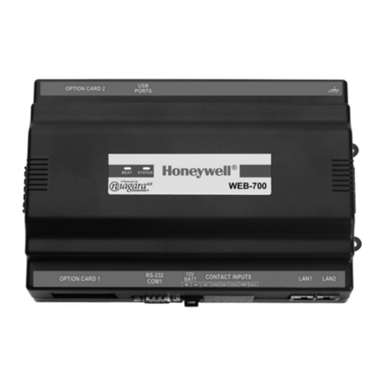
The WEB-700 and CP-700 are compact, embedded
controller/server platforms that allow integrated control
and management of external devices over the Internet.
They provide suppport for two optional communications
boards as well as optional remote I/O expansion
modules.
CONTENTS
Mounting 7
Board Layout 11
Grounding 17
Power Wiring 18
INSTALLATION INSTRUCTIONS
Apply Power 22
About LEDs 24
Status 24
Heartbeat 24
Debug 24
USB 24
Cleaning 25
Put Bar Code Here
95-7776-01
Table of Contents

Related Manuals for Honeywell WEB-700


Summary of Contents for Honeywell WEB-700
-
Page 1: Table Of Contents
WEB-700-O CP-700 INSTALLATION INSTRUCTIONS APPLICATION The WEB-700 and CP-700 are compact, embedded controller/server platforms that allow integrated control and management of external devices over the Internet. They provide suppport for two optional communications boards as well as optional remote I/O expansion modules. -
Page 2: About This Guide
WEB-700 WEB-700-O CP-700 WEB-700; WEB-700-O; CP-700 ABOUT THIS GUIDE This document covers the mounting and wiring of the Tridium® WEB/CP-700 (T-700) controller. It assumes that you are an engineer, technician, or service person who is performing control system installation. Instructions in this document apply to the... -
Page 3: Product Description
WEB-700 WEB-700-O CP-700 WEB-700; WEB-700-O; CP-700 PRODUCT DESCRIPTION The WEB/CP-700 controller is a compact embedded processor platform using on-board Flash memory for backup, in an expandable DIN-modular package. Designed for use in commercial environments, the WEB/CP-700 runs the NiagaraAX Framework to provide integrated control, supervision, and network management solutions for wide variety of networked field devices. - Page 4 WEB-700 WEB-700-O CP-700 WEB-700; WEB-700-O; CP-700 NiMH battery pack Removed and shield removed option cards USB ports (2) Main controller board DIN-mount base with screw tabs for panel mount Connector ports Fig. 2. WEB/CP-700 main controller board and 2 option cards uninstalled.
-
Page 5: Technical Specifications
WEB-700 WEB-700-O CP-700 WEB-700; WEB-700-O; CP-700 Technical Specifications WEB/CP-700 PLATFORM • PowerPC 440Epx @ 667MHz processor (speed approximate due to spread spectrum clock). • 1GB on-board NAND Flash storage. • Base 512MB DDR-2 333Mhz RAM, field-upgradable to 1GB (industrial-grade, sourced from Tridium). -
Page 6: Preparation
WEB-700 WEB-700-O CP-700 WEB-700; WEB-700-O; CP-700 PREPARATION Unpack the WEB/CP-700 and inspect the package contents for damaged or missing components. If damaged, notify the appropriate carrier at once and return any damaged components for immediate repair or replacement. See “Returning a Defective Unit”... -
Page 7: Static Discharge Precautions
WEB-700 WEB-700-O CP-700 WEB-700; WEB-700-O; CP-700 WARNING A 120Vac or 240Vac circuit powers the NPB-PWR-UN-H power supply for the controller. Disconnect power before installation or servicing to prevent electrical shock or equipment damage. Make all connections in accordance with national and local electrical codes. Use copper conductors only. -
Page 8: Environmental Requirements
WEB-700 WEB-700-O CP-700 WEB-700; WEB-700-O; CP-700 Environmental Requirements Note the following requirements for the WEB/CP-700 mounting location: • If mounting inside an enclosure, that enclosure should be designed to keep the unit within its required operating range considering a 20-watt dissipation by the controller, plus dissipation from any other devices installed in the same enclosure. - Page 9 WEB-700 WEB-700-O CP-700 WEB-700; WEB-700-O; CP-700 Fig. 3 and the following procedure provides step-by-step DIN rail mounting instructions for the WEB/CP-700. Mounting on Removing from DIN rail DIN rail WEB/CP-700 NPB-PWR-UN-H DIN rail end clip Secure controller or last directly attached I/O module...
-
Page 10: Removing And Replacing The Cover
WEB-700 WEB-700-O CP-700 WEB-700; WEB-700-O; CP-700 6. If installing any I/O expansion modules, repeat this for each one, until all are mounted on the DIN rail and firmly connected into one assembly. 7. To keep the final assembly together, secure at both ends with DIN rail end-clips provided by the DIN rail vendor. This also prevents the assembly from sliding on the DIN rail. -
Page 11: Board Layout
WEB-700 WEB-700-O CP-700 WEB-700; WEB-700-O; CP-700 Board Layout Fig. 5 shows the location of connectors, option slots, and other features of the main board in the WEB/CP-700. For side views of communications ports and other features, see Fig. 7, page 16. -
Page 12: About Expansion Options
• MiniPCI option card — (future use). See About MiniPCI Cards, page 15. About Option Cards The WEB-700/CP has two (2) available option slots to accept a custom option card, compatible with either of these types: • Series 2 and 6 controller options cards: 30-pin, 2 row connector, or •... -
Page 13: About Ddr-2 Ram Upgrade
WEB-700 WEB-700-O CP-700 WEB-700; WEB-700-O; CP-700 OPTION CARD COM PORT ASSIGNMENTS COM port assignments for option cards installed in a WEB/CP-700 start at COM5, with Slot 1 evaluated first, then Slot 2. (COM1 and COM2 are always assigned to the onboard RS-232 and RS-485 ports, while COM3 and COM4 are reserved for slots.) INSTALLING AN OPTION CARD For option-specific details, see the mounting &... - Page 14 WEB-700 WEB-700-O CP-700 WEB-700; WEB-700-O; CP-700 Option card in Slot 2 must be installed under the shield tab. Shield Tab Option card or blanking plate in Slot 1 must be removed before shield can be Shield with NiMH removed. battery assembly...
-
Page 15: About Remote I/O Modules
WEB-700 WEB-700-O CP-700 WEB-700; WEB-700-O; CP-700 About Remote I/O Modules The WEB/CP-700 has an integral 6-pin connector to support remote I/O modules. The connector provides both 15Vdc power and RS-485 communications to modules on that connected trunk, and is located on the right side of the unit. - Page 16 WEB-700 WEB-700-O CP-700 WEB-700; WEB-700-O; CP-700 Top side USB ports (2) Right side 15V PS -, + and 12V Backup Battery out Option slot 2 connector area Bottom side RS-485 COM2 Option slot 1 connector area LAN 2 Ethernet (RJ-45)
-
Page 17: Grounding
WEB-700 WEB-700-O CP-700 WEB-700; WEB-700-O; CP-700 NOTE: If rebooted with the mode jumper in the “Serial Shell” position (see Fig. 5, page 11), the RS-232 port provides “system shell” access. See the NiagaraAX Install and Startup Guide for related details. -
Page 18: Power Wiring
WEB-700 WEB-700-O CP-700 WEB-700; WEB-700-O; CP-700 WEB/CP-700 NPB-PWR-UN-H Grounding lug (remove cover) Supplied earth grounding wire 20-pin connector not used AC Input Line Grounding lug Neutral 120 or 240Vac 50–60 Hz Earth Ground Single Phase Fig. 8. Grounding and power wiring connections to NPB-PWR-UN-H module. - Page 19 WEB-700 WEB-700-O CP-700 WEB-700; WEB-700-O; CP-700 Wiring NPB-PWR-UN-H input power and earth ground. 1. Remove power from the AC circuit being wired to the NPB-PWR-UN-H—see previous . 2. Remove the NPB-PWR-UN-H cover. To do this, press in the four tabs on both ends of the unit, and lift the cover off. If the WEB/CP-700 is plugged into the unit, you may need to slide it away to get to the cover tabs.
-
Page 20: Contact Inputs
WEB-700 WEB-700-O CP-700 WEB-700; WEB-700-O; CP-700 Contact Inputs Three contact inputs (CIs) are available on a 6-position connector next to the 2-position external battery connector. CIs are typically used to monitor normally-closed (N.C.) alarm contacts, if available on a UPS and/or the “door tamper” switch of an enclosure. -
Page 21: External 12V Backup Battery
WEB-700 WEB-700-O CP-700 WEB-700; WEB-700-O; CP-700 EXTERNAL 12V BACKUP BATTERY A 2-position connector provides support for an external 12V sealed lead-acid (SLA) type rechargable battery. For more details, see About the Backup Batteries, page 23. WEB/ CP-700 P S –... -
Page 22: Wiring To Remote I/O Modules
WEB-700 WEB-700-O CP-700 WEB-700; WEB-700-O; CP-700 Wiring to Remote I/O Modules Wiring to remote I/O modules typically provides both 15Vdc power and 12V battery backup, along with RS-485 communications to the modules. See Fig. 12. Connect shield wire to ground at one end only WEB/CP-700 P S –... -
Page 23: About The Backup Batteries
WEB-700 WEB-700-O CP-700 WEB-700; WEB-700-O; CP-700 If after applying power, the STATUS LED goes out, or if the BEAT LED comes on (steady) and stays lit longer than 2 minutes, contact your local distributor for technical assistance. See also “About LEDs” on page 24. -
Page 24: About Leds
WEB-700 WEB-700-O CP-700 WEB-700; WEB-700-O; CP-700 ABOUT LEDS The WEB/CP-700 provides a number of LEDs on its main board. Only the Status and Heartbeat LEDs are visible on the cover. Checking other LEDs requires first removing the cover. LEDs include the following types: •... -
Page 25: Cleaning
WEB-700 WEB-700-O CP-700 WEB-700; WEB-700-O; CP-700 Cleaning If dust or metal filings are present inside the unit, clean with vacuum or compressed air. Otherwise, no cleaning inside the unit is required. If the cover becomes dirty, you can wipe it with a damp cloth and mild detergent. - Page 26 WEB-700 WEB-700-O CP-700 WEB-700; WEB-700-O; CP-700 Cover removed NiMH battery pack (NPB-BATT-7) Unplug/plug NiMH battery from/to connector 1/4" (6mm) Kep nuts (2) fasten battery bracket to shield Battery bracket NiMH battery connector on controller board Fig. 13. Replacing NiMH battery pack in WEB/CP-700.
-
Page 27: Replacement Parts
WEB-700 WEB-700-O CP-700 WEB-700; WEB-700-O; CP-700 REPLACEMENT PARTS Servicing the WEB/CP-700 may call for replacement parts. There are three categories of parts: • Non-replaceable Parts • Standard Replacement Parts • New Replacement Unit Non-replaceable Parts FUSE The WEB/CP-700 contains a non-user replaceable 2.5A slow-blow fuse, soldered on the main circuit board. This fuse provides protection from internal shorts or connection to incorrect power supplies. - Page 28 WEB-700 WEB-700-O CP-700 WEB-700; WEB-700-O; CP-700 4. Note positions of all communications and other wiring cables going to the controller. If necessary, label connectors and accessory modules to avoid mis-connection later, after WEB/CP-700 is replaced. 5. Unplug all Ethernet, serial, LON, modem, and I/O connectors from the controller. Note the position of installed option cards, if any.
-
Page 29: Certifications
WEB-700 WEB-700-O CP-700 WEB-700; WEB-700-O; CP-700 CERTIFICATIONS Federal Communications Commission (FCC) This equipment generates, uses, and can radiate radio frequency energy, and if not installed and used in accordance with the instruction manual, may cause interference with radio communications. It has been tested and found to comply with the limits for a Class A computing device pursuant to Subpart J of Part 15 of FCC Rules, which are designed to provide reasonable protection against such interference when operated in a commercial environment. -
Page 30: Tab Mounting Dimensions
WEB-700 WEB-700-O CP-700 WEB-700; WEB-700-O; CP-700 TAB MOUNTING DIMENSIONS Measurements are in inches and (mm). DIN mounting is recommended over tab mounting. See Fig. 3, page 9. NOTE: Electronic and printed versions of this guide may not show the dimensions to scale. - Page 31 WEB-700 WEB-700-O CP-700 WEB-700; WEB-700-O; CP-700 NPB-PWR-UN-H 3.48” 2.50" (88.55) (63.5) 8.125" (206) Distance between center of tabs from one unit to another unit Fig. 15. WEB/CP-700 with power supply attached. 95-7776—01...
- Page 32 Automation and Control Solutions Honeywell International Inc. 1985 Douglas Drive North Golden Valley, MN 55422 Honeywell Limited-Honeywell Limitée 35 Dynamic Drive ® U.S. Registered Trademark Toronto, Ontario M1V 4Z9 © 2010 Honeywell International Inc. 95-7776—01 M.S. 03-10 customer.honeywell.com Printed in U.S.A.