Honeywell EXCEL 10 Installation Instructions Manual
Fan coil unit
controllers
Hide thumbs
Also See for EXCEL 10:
- Quick manual (13 pages) ,
- Installation instructions manual (8 pages) ,
- Installation instructions (4 pages)
Quick Links
See also:
Quick Manual
HONEYWELL EXCEL 5000 OPEN SYSTEM
GENERAL INFORMATION
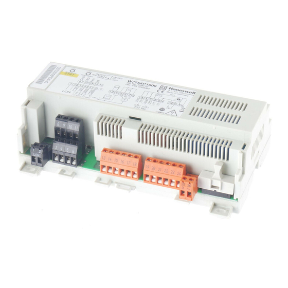
LonWorks SERVICE BUTTON
LonWorks
LEFT DIP SWITCH (USED = WALL MODULE CONNECTED)
SERVICE LED
RIGHT DIP SWITCH (USED = TERMINAL 11 ENABLED)
TERMINAL ASSIGNMENT LABEL
RELAYS
ANALOG OUTPUT & ANALOG INPUTS
REMOVABLE LonWorks TERMINAL PLUG
BINARY OUTPUT FOR LOW-VOLTAGE PWM
CONTROL OF SOLID-STATE RELAY (W7754K, only)
Fig. 1. Excel 10 W7754 FCU Controller (w/o opt. cover)
OS no.
W7754K1001
230 VAC
230 VAC
W7754P1000
230 VAC
230 VAC
24 VAC
24 VAC
W7754Q1008
W7754R4431
230 VAC
230 VAC
W7754S2230
230 VAC
230 VAC
W7754T4431
230 VAC
24 VAC
W7754V1230
230 VAC
230 VAC
® U.S. Registered Trademark
Copyright © 2016 Honeywell Inc.
All Rights Reserved
W7754K,P,Q,R,S,T,V FAN COIL UNIT
BEFORE INSTALLATION
IMPORTANT
乨 CAUTION
TRIACS
FUSE
REMOVABLE POWER
SUPPLY TERMINAL PLUG
X
X
X
X X
X
X
X
X X
X
X
X
X X
X
X
X
X X
X
X
X
X X
X
X
X
X X
X
X
--
-- --
Table 1. Overview of models
CONTROLLERS
INSTALLATION INSTRUCTIONS
It is recommended that the unit be kept at room
temperature for at least 24 hours before applying
power; this is to allow the evaporation of any
condensation resulting from low shipping / storage
temperatures.
US requirement, only: This device must be installed
in a UL-listed enclosure offering adequate space to
maintain the segregation of line voltage field wiring
and Class 2 field wiring.
To avoid electrical shock or equipment damage, you
must switch OFF the power supply before attaching /
removing connections to/from any terminals.
--
-- -- --
X
X
X
X
X
X
X
--
X
X
X
X
X
--
X
X
X
X
X
--
--
--
X --
X
--
X
X
X
X
X
--
X
--
X --
X
--
Excel 10
--
X
X X
X
--
X
X X
X
--
X
X X
X
X
X
X X
X
--
X
X X
X
X
X
X X
X
X
X
X X
X
EN1B-0304GE51 R0916M

Related Manuals for Honeywell EXCEL 10


Summary of Contents for Honeywell EXCEL 10
- Page 1 SUPPLY TERMINAL PLUG removing connections to/from any terminals. REMOVABLE LonWorks TERMINAL PLUG BINARY OUTPUT FOR LOW-VOLTAGE PWM CONTROL OF SOLID-STATE RELAY (W7754K, only) Fig. 1. Excel 10 W7754 FCU Controller (w/o opt. cover) OS no. W7754K1001 230 VAC 230 VAC...
- Page 2 EXCEL 10 W7754K,P,Q,R,S,T,V FCU CONTROLLERS − INSTALLATION INSTRUCTIONS MOUNTING Wall Mounting/Dismounting The unit can be mounted on walls in any desired orientation. All models have the same dimensions (W x L x H = The unit is mounted by inserting 3.5-mm dowel screws 110 x 180 x 60 mm) (see Fig.
- Page 3 EXCEL 10 W7754K,P,Q,R,S,T,V FCU CONTROLLERS − INSTALLATION INSTRUCTIONS Table 2. W7754 Controller: Overview of terminals and functions (by model) model term. function Removable plug; receiving/sending data on the L network ORKS BINARY INPUT (DI1), configurable (via the LNS plug-in) to read input from, e.g., a hardwired window contact, occupancy sensor, etc.;...
- Page 4 EXCEL 10 W7754K,P,Q,R,S,T,V FCU CONTROLLERS − INSTALLATION INSTRUCTIONS Power Supply Electrical Data 230 Vac +10%, -15%, 50/60 Hz; W7754K,P,R,S,V: General Information max. 6 VA power consumption (unloaded) 230 Vac +10%, -15%, 50/60 Hz; W7754T: max. 12 VA power consumption (unloaded) CAUTION 24 Vac 20%, 50/60 Hz...
- Page 5 EXCEL 10 W7754K,P,Q,R,S,T,V FCU CONTROLLERS − INSTALLATION INSTRUCTIONS Configuration of the Wall Module's LED / LCD is displayed continuously, the controller is in the "unoccupied" mode; if it flashes, the "unoccupied" mode When either a T7460 or a T7560 Wall Module has been has been overridden.
- Page 6 EXCEL 10 W7754K,P,Q,R,S,T,V FCU CONTROLLERS − INSTALLATION INSTRUCTIONS Depending upon the chosen network configuration, one or two Hardware Limits for W7754K,P,R,S,T,V (230 Vac Power Supply) terminations (see section "L Termination" on page Low signal: 0 V; high signal: 230 Vac ORKS 8) may be required.
- Page 7 EXCEL 10 W7754K,P,Q,R,S,T,V FCU CONTROLLERS − INSTALLATION INSTRUCTIONS Table 6. W7754S,V Output assignments Table 9. Use of the analog output (W7754V, function output output output output OUT1 OUT2 output only) stage 1 mode 1 type 2 mode 2 type type var.-speed fan...
- Page 8 EXCEL 10 W7754K,P,Q,R,S,T,V FCU CONTROLLERS − INSTALLATION INSTRUCTIONS Possible Problems and Recommended Actions OUTPUT 2 Check if the L service LED's behavior is changed if ORKS 10.0 V AO (0...100% = 0...10 V), you switch the power OFF/ON. Please contact Honeywell if no feedback on LonWorks network this does not solve the problem.
- Page 9 EXCEL 10 W7754K,P,Q,R,S,T,V FCU CONTROLLERS − INSTALLATION INSTRUCTIONS Temperature Control Accuracy (CA) Table 10. L Service LED Behaviors and ORKS Meanings W7754P1000, W7754Q1008 with Motorized Actuator LED blinking pattern meaning FCU heating mode: 0.5 K FCU cooling mode: 0.2 K Defective device hardware.
- Page 10 EXCEL 10 W7754K,P,Q,R,S,T,V FCU CONTROLLERS − INSTALLATION INSTRUCTIONS Manufactured for and on behalf of the Environmental & Energy Solutions Division of Honeywell Technologies Sàrl, Rolle, Z.A. La Pièce 16, Switzerland by its Authorized Representative: Automation and Control Solutions Honeywell GmbH Böblinger Strasse 17...