Table of Contents
Table of Contents

Related Manuals for Honeywell CUL6438SR-CV1


Summary of Contents for Honeywell CUL6438SR-CV1
- Page 1 STRYKER CVAHU ZIO CUL6438SR-CV1 CONFIGURATION GUIDE Nov-2013 31-00023-01...
-
Page 2: Table Of Contents
STRYKER CVAHU ZIO CONFIGURATION GUIDE Table of Contents Introduction ................................9 Description of Devices ..........................9 Stryker™ Lon Configurable CVAHU Controller ................9 General ..........................9 Features ..........................9 Zio®/Zio Plus LCD Wall Modules ....................10 General ..........................10 Features ..........................10 Control Application ........................ - Page 3 STRYKER CVAHU ZIO CONFIGURATION GUIDE AO2 ........................... 44 AO3 ........................... 45 Cnfg Out ........................46 Time .......................... 50 Set Time ........................51 Set Date........................51 Schedule........................53 Tenant Mode: Introduction ........................54 Tenant Mode: View Steps ......................54 Fan ............................. 55 Override..........................
- Page 4 STRYKER CVAHU ZIO CONFIGURATION GUIDE List of Figures Figure 1: Stryker™ Lon Configurable CVAHU Controller ..................9 Figure 2: Zio/Zio Plus LCD Wall Modules....................... 10 Figure 3: Typical Stryker CVAHU control application ..................... 11 Figure 4: Stryker CVAHU configuration by Zio wall module ................... 15 Figure 5: Key position of wall module ........................
- Page 5 STRYKER CVAHU ZIO CONFIGURATION GUIDE Figure 37: Parameter Alarms Clg Ovrd ........................28 Figure 38: Parameter Alarms Htg Ovrd ........................29 Figure 39: Parameter Alarms Fan Ovrd........................29 Figure 40: Parameter Alarms Frost ........................29 Figure 41: Parameter Alarms Iaq Alm ........................29 Figure 42: Parameter Alarms Invld Sp........................
- Page 6 STRYKER CVAHU ZIO CONFIGURATION GUIDE Figure 76: Parameter Cnfg In Od Temp ......................... 42 Figure 77: Parameter Cnfg In Occ Snsr ......................... 43 Figure 78: Parameter Cnfg In Window ........................43 Figure 79: Parameter AO1 Range.......................... 44 Figure 80: Parameter AO2 Range.......................... 44 Figure 81: Parameter AO3 Range..........................
- Page 7 STRYKER CVAHU ZIO CONFIGURATION GUIDE List of Tables Table 1: Stryker reference documents........................9 Table 2: Zio reference documents .......................... 10 Table 3: List of applicable literature ........................12 Table 4: Agency listing ............................13 Table 5: TR values used by the space cooling pid control..................35 Table 6: IT values used by the space cooling pid control.
- Page 8 STRYKER CVAHU ZIO CONFIGURATION GUIDE...
-
Page 9: Introduction
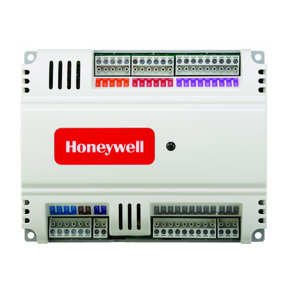
Figure 1: Stryker™ Lon Configurable CVAHU Controller General Form No. Title Stryker™ Lon Configurable The CUL6438SR-CV1 is part of the Stryker family. 63-4529—03 VAV/CVAHU Controller The controllers are Free Topology Transceiver Specification Data (FTT) LONMARK®-certified devices designed to Stryker™ Lon Configurable control HVAC equipment. -
Page 10: Zio®/Zio Plus Lcd Wall Modules
Customized parameter access, by using the the system fan. Control of heat pump units, where Honeywell WEBs-AX Workbench tool. the compressor(s) is used for both cooling and Ability to link setpoint limits to a network heating, is also provided. -
Page 11: Control Provided
STRYKER CVAHU ZIO CONFIGURATION GUIDE Figure 3 shown below is typical Stryker CVAHU control application. Figure 3: Typical Stryker CVAHU control application Control Provided indoor air quality (IAQ) needs in the space. IAQ The Stryker CVAHU Controller is designed to monitoring is provided through either a CO sensor control a single air handler to maintain the unit’s... -
Page 12: Products Covered
Stryker LON CVAHU controller is available as one model. Organization of Manual CUL6438SR-CV1: Constant volume air handling unit controller from Stryker LON family. This manual is divided into two basic parts: The TR70 series Zio wall module is available in four introduction and configuration. -
Page 13: Agency Listings
File number - E87741 Listed (E87741). LR95329-3 listed. Meets FCC Part 15, Subpart B, Class B (radiated emissions) CUL6438SR-CV1 requirements. controller Meets Canadian standard C108.8 (radiated emissions). Conforms to the following requirements per European Consortium standards: EN 61000-6-1;... -
Page 14: Abbreviations
STRYKER CVAHU ZIO CONFIGURATION GUIDE Abbreviations I/O: Input/Output; the physical sensors and actuators connected to a controller. AHU: Air Handling Unit. The central fan system I * R: I times R or current times resistance; refers to includes the blower, heating equipment, cooling Ohm’s Law: V = I x R. -
Page 15: Stryker Cvahu Configuration By Zio Wall Module
STRYKER CVAHU ZIO CONFIGURATION GUIDE Compatibility STRYKER CVAHU The TR70 Series LCD Wall Modules operate with the Sylk Enhanced Stryker controller. The TR71/TR75 CONFIGURATION can replace a TR70 in an installation where an upgrade to WEBs- AX or Stryker or reprogramming is BY ZIO WALL not desired. -
Page 16: Initial Power-Up
STRYKER CVAHU ZIO CONFIGURATION GUIDE Initial Power-Up Controller features not supported by Zio configuration Network functionality IMPORTANT: Accessory loops 1. Make sure the TR70 Series wall module is properly mounted and properly wired and Custom sensors connected to the programmable controller. ... -
Page 17: Contractor Mode: Configuration Steps
STRYKER CVAHU ZIO CONFIGURATION GUIDE Contractor Mode: Configuration Steps The Contractor Mode screen as shown in Figure 8 Figure 9: Home screen Roomtemp Figure 8: Contractor mode default home screen The three soft keys on the contractor home screen Home screen: ROOMTEMP provide the following three options Description: Default home screen displays room temperature (setpoint is not adjusted from this home... -
Page 18: Set View More
STRYKER CVAHU ZIO CONFIGURATION GUIDE Set View More SET VIEW MORE allows the contractor to provide parameter access (view only or adjustable) to the tenant’s VIEW MORE soft key. Click SET VIEW MORE soft key to display the first configured parameter as shown in Figure Figure 11: Home screen Outside Room Temperature... - Page 19 STRYKER CVAHU ZIO CONFIGURATION GUIDE 52. EFHTG LO After clicking NEXT on particular screen, parameters 53. EFCLH HI are displayed in following order. 54. EFCLG LO ZIO HUM 55. HP TYPE ROOMTEMP 56. CLG TYPE 57. CLG TR 58. CLG IT DISCHRG 59.
-
Page 20: Parameters
STRYKER CVAHU ZIO CONFIGURATION GUIDE Click NEXT on SENSORS parameter group screen. Parameters Other parameter group screens are displayed in following order. PARAMETERS allow the contractor to monitor and/or adjust parameters in the programmable controller. Status Click PARAMETERS soft key on contractor mode Temp SP default home screen to display the first configured Override... -
Page 21: Sensors
STRYKER CVAHU ZIO CONFIGURATION GUIDE Sensors DISCHRG: Displays discharge air temperature and is (CVAHU sensor value display) an input to the Sbus wall module function block. Click the PARAMETERS soft key to display the first configured category ‘SENSORS’. Within this OAT: Displays outside air temperature and is an input category, one sample Zio display is shown for to the Sbus wall module function block. -
Page 22: Status
STRYKER CVAHU ZIO CONFIGURATION GUIDE Status (CVAHU parameter status display) Figure 17: Parameter Status Htg Out Figure 19: Parameter Status Damper HTG OUT: Displays cooling output signal. DAMPER: Displays damper (%) output signal. Figure 18: Parameter Status Clg Out Figure 20: Parameter Status Dmd Limit CLG OUT: Displays heating output signal. -
Page 23: Figure 21: Parameter Status Trmnl Ld
STRYKER CVAHU ZIO CONFIGURATION GUIDE Figure 21: Parameter Status Trmnl Ld Figure 23: Parameter Status Free Mod TRMNL LD: Displays effective terminal load (%) on FREE MOD: Displays configured free modulating1 the controller. Its value ranges from 160% to 160%. A (%) output signal. -
Page 24: Figure 25: Parameter Status Fan
STRYKER CVAHU ZIO CONFIGURATION GUIDE Figure 25: Parameter Status Fan FAN: Displays fan digital output status as ON or OFF. Configuration settings in program are as follows: 0 = OFF, 1 = ON, 255 = UNDEFINED... -
Page 25: Temp Sp
STRYKER CVAHU ZIO CONFIGURATION GUIDE Temp Sp (CVAHU temperature setpoint configuration) Figure 26: Parameter Temp Sp Occ Clg Figure 28: Parameter Temp Sp Unoc Clg OCC CLG: Displays and allows modification of UNOC CLG: Displays and allows modification of occupied cooling setpoint. Its value ranges from unoccupied cooling setpoint. -
Page 26: Figure 30: Parameter Temp Sp Stby Clg
STRYKER CVAHU ZIO CONFIGURATION GUIDE Figure 30: Parameter Temp Sp Stby Clg Figure 32: Parameter Temp Sp Setpoint SETPOINT: Displays and allows modification of STBY CLG: Displays and allows modification of centre setpoint read from wall module. Its value standby cooling setpoint. Its value ranges from OCC ranges from CNTSP LO to CNTSP HI. -
Page 27: Figure 34: Parameter Temp Sp Eff Sp
STRYKER CVAHU ZIO CONFIGURATION GUIDE Figure 34: Parameter Temp Sp Eff Sp EFF SP: Displays room temperature effective setpoint. Its value ranges from 40 to 100. -
Page 28: Override
STRYKER CVAHU ZIO CONFIGURATION GUIDE Override Alarms (CVAHU override used for fan) (CVAHU parameter alarms) Figure 36: Parameter Alarms Emrg Ovrd Figure 35: Parameter Override Fan Ovrd EMRG OVRD: Displays smoke detector status as FAN OVRD: Displays and allows modification of TRUE, FALS or UNDEFINED. -
Page 29: Figure 38: Parameter Alarms Htg Ovrd
STRYKER CVAHU ZIO CONFIGURATION GUIDE Figure 40: Parameter Alarms Frost Figure 38: Parameter Alarms Htg Ovrd FROST: Displays frost override status as TRUE, HTG OVRD: Displays heating override status as FALS or UNDEFINED. TRUE, FALS or UNDEFINED. Configuration settings in program are as follows: Configuration settings in program are as follows: 0 = FALS, 1 = TRUE, 255 = UNDEFINED 0 = FALS, 1 = TRUE, 255 = UNDEFINED... -
Page 30: Figure 42: Parameter Alarms Invld Sp
STRYKER CVAHU ZIO CONFIGURATION GUIDE Figure 42: Parameter Alarms Invld Sp INVLD SP: Displays invalid setpoint override status as TRUE, FALS or UNDEFINED. Configuration settings in program are as follows: 0 = FALS, 1 = TRUE, 255 = UNDEFINED Figure 43: Parameter Alarms Spc Temp SPC TEMP: Displays space temperature override status as TRUE, FALS or UNDEFINED. -
Page 31: Snsr Calibration
STRYKER CVAHU ZIO CONFIGURATION GUIDE Snsr Calibration Wm Config (CVAHU sensor calibration) (CVAHU wall module configuration) Figure 46: Parameter Wm Config Units Figure 44: Parameter Snsr Cal Zio T Of UNITS: Displays and allows modification of units to ZIO T OF: Displays and allows modification of Zio be displayed for temperature parameters as C, F, temperature offset. -
Page 32: Figure 48: Parameter Wm Config Cntr Sp
STRYKER CVAHU ZIO CONFIGURATION GUIDE Figure 48: Parameter Wm Config Cntr Sp Figure 50: Parameter Wm Config Cntsp Lo CNTR SP: Displays and allows modification of centre CNTSP LO: I Displays and allows modification of centre setpoint low limit. Its value ranges from –10 to setpoint as FALS, TRUE, UNDEFINED. -
Page 33: Figure 52: Parameter Wm Config Htgsp Hi
STRYKER CVAHU ZIO CONFIGURATION GUIDE Figure 54: Parameter Wm Config Clgsp Hi Figure 52: Parameter Wm Config Htgsp Hi CLGSP HI: Displays and allows modification of HTGSP HI: Displays and allows modification of cooling setpoint high limit. Its value ranges from heating setpoint high limit. -
Page 34: Figure 56: Parameter Wm Config Efhtg Hi
STRYKER CVAHU ZIO CONFIGURATION GUIDE Figure 58: Parameter Wm Config Efclg HI Figure 56: Parameter Wm Config Efhtg HI EFCLG HI: Displays effective cooling high setpoint. EFHTG HI: Displays effective heating high setpoint. Figure 57: Parameter Wm Config Efhtg Lo Figure 59: Parameter Wm Config Efclg Lo EFHTG LO: Displays effective heating low setpoint. -
Page 35: Cnfg Ctl
STRYKER CVAHU ZIO CONFIGURATION GUIDE Cnfg Ctl Note: (CVAHU configuration for control) 1. Modulating cooling not compatible with Econo_Type = 1 Packaged. 2. Modulating compressor is not supported for heat pump control. 3. Automatic Gain Selection feature is enabled when Throttling Range (TR) is 0. Default TR is 0. -
Page 36: Figure 63: Parameter Cnfg Ctl Clg It
STRYKER CVAHU ZIO CONFIGURATION GUIDE Figure 64: Parameter Cnfg Ctl Htg Type Figure 63: Parameter Cnfg Ctl Clg It HTG TYPE: Displays and allows modification of CLG IT: Displays and allows modification of cooling heating output type for conventional or heat pump PID control integral time. -
Page 37: Figure 65: Parameter Cnfg Ctl Htg Tr
STRYKER CVAHU ZIO CONFIGURATION GUIDE Figure 65: Parameter Cnfg Ctl Htg Tr Figure 66: Parameter Cnfg Ctl Htg It HTG IT: Displays and allows modification of heating HTG TR: Displays and allows modification of space PID control integral time. Its value ranges from 0 to heating PID control throttling range. -
Page 38: Figure 67: Parameter Cnfg Ctl Fan Mode
STRYKER CVAHU ZIO CONFIGURATION GUIDE Figure 68: Parameter Cnfg Ctl Oc Snorp Figure 67: Parameter Cnfg Ctl Fan Mode OC SNORP: Displays and allows modification of FAN MODE: Displays and allows modification of fan occupancy sensor operation status. This can be mode to be used for CVAHU. -
Page 39: Cnfg Ui
STRYKER CVAHU ZIO CONFIGURATION GUIDE Cnfg Ui Cnfg Di (Configuration of CVAHU universal inputs) (Configuration of CVAHU digital inputs) Figure 70: Parameter Cnfg Di Di 1 Figure 69: Parameter Cnfg Ui Ui 1 DI 1: Displays and allows modification of input type UI 1: Displays and allows modification of input type for digital input 1. -
Page 40: Cnfg In
STRYKER CVAHU ZIO CONFIGURATION GUIDE Cnfg In (Configuration of CVAHU inputs) Figure 71: Parameter Cnfg In Spe Temp Figure 72: Parameter Cnfg In Spe Rh SPC TEMP: Displays and allows modification of SPC RH: Displays and allows modification of logical logical input configuration /terminal assignment for input configuration /terminal assignment for space space temperature. -
Page 41: Figure 73: Parameter Cnfg In Spe Co
STRYKER CVAHU ZIO CONFIGURATION GUIDE Figure 73: Parameter Cnfg In Spe CO Figure 74: Parameter Cnfg In Dischair DISCHAIR: Displays and allows modification of SPC CO : Displays and allows modification of logical logical input configuration /terminal assignment for input configuration /terminal assignment for space discharge air temperature. -
Page 42: Figure 75: Parameter Cnfg In Mixedair
STRYKER CVAHU ZIO CONFIGURATION GUIDE Figure 76: Parameter Cnfg In Od Temp Figure 75: Parameter Cnfg In Mixedair OD TEMP: Displays and allows modification of logical MIXEDAIR: Displays and allows modification of input configuration /terminal assignment for outside logical input configuration /terminal assignment for air temperature. -
Page 43: Figure 77: Parameter Cnfg In Occ Snsr
STRYKER CVAHU ZIO CONFIGURATION GUIDE Figure 78: Parameter Cnfg In Window Figure 77: Parameter Cnfg In Occ Snsr WINDOW: Displays and allows modification of logical OCC SNSP: Displays and allows modification of input configuration /terminal assignment for window logical input configuration /terminal assignment for contacts. -
Page 44: Ao1
STRYKER CVAHU ZIO CONFIGURATION GUIDE (Analog output1 range configuration) (Analog output2 range configuration) Figure 80: Parameter AO2 Range Figure 79: Parameter AO1 Range RANGE: Displays and allows modification of analog RANGE: Displays and allows modification of analog output2 range. This can be changed as 0D10, 10D0, output1 range. -
Page 45: Ao3
STRYKER CVAHU ZIO CONFIGURATION GUIDE (Analog output3 range configuration) Figure 81: Parameter AO3 Range RANGE: Displays and allows modification of analog output3 range. This can be changed as 0D10, 10D0, 2D10, 10D2, 0A20, 20A0, 0A22, 22A0, 4A20, 20A4, DIG, and UNDEFINED. Default Parameter setting: UNDEFINED Configuration settings in program are as follows: = 0D10 (Analog voltage 0 to 10VDC direct... -
Page 46: Cnfg Out
STRYKER CVAHU ZIO CONFIGURATION GUIDE Cnfg Out (Configuration of CVAHU analog and digital outputs) Figure 83: Parameter Cnfg Out Clg Stg2 Figure 82: Parameter Cnfg Out Clg Stg1 CLG STG2: Displays and allows modification of CLG STG1: Displays and allows modification of logical output configuration /terminal assignment for logical output configuration /terminal assignment for Cooling or Heat Pump stage 2 Command. -
Page 47: Figure 84: Parameter Cnfg Out Clg Stg3
STRYKER CVAHU ZIO CONFIGURATION GUIDE Figure 84: Parameter Cnfg Out Clg Stg3 Figure 85: Parameter Cnfg Out Hp Chang HP CHANG: Displays and allows modification of CLG STG3: Displays and allows modification of logical output configuration /terminal assignment for logical output configuration /terminal assignment Heat Pump change over relay command. -
Page 48: Figure 86: Parameter Cnfg Out Htg Stg1
STRYKER CVAHU ZIO CONFIGURATION GUIDE Figure 87: Parameter Cnfg Out Htg Stg2 Figure 86: Parameter Cnfg Out Htg Stg1 HTG STG2: Displays and allows modification of HTG STG1: Displays and allows modification of logical output configuration /terminal assignment for logical output configuration /terminal assignment for Heating stage 2 Command. -
Page 49: Figure 88: Parameter Cnfg Out Htgstg3
STRYKER CVAHU ZIO CONFIGURATION GUIDE Figure 89: Parameter Cnfg Out Fan Out Figure 88: Parameter Cnfg Out HtgStg3 FAN OUT: Displays and allows modification of logical HTG STG3: Displays and allows modification of output configuration /terminal assignment for Fan logical output configuration /terminal assignment for Start-Stop Command. -
Page 50: Time
STRYKER CVAHU ZIO CONFIGURATION GUIDE Time (CVAHU controller time display) Figure 91: Parameter Time Time Figure 90: Parameter Cnfg Out Damper TIME: Displays current time in HH MM format. DAMPER: Displays and allows modification of logical output configuration /terminal assignment for Damper control signal. -
Page 51: Set Time
STRYKER CVAHU ZIO CONFIGURATION GUIDE Set Time Set Date (CVAHU controller time configuration/settings) (CVAHU controller date configuration/settings) Figure 92: Parameter Set Time Hours Figure 94: Parameter Set Date Year HOURS: Displays and allows modification of time in YEAR: Displays and allows modification of date in hours. -
Page 52: Figure 96: Parameter Set Date Day
STRYKER CVAHU ZIO CONFIGURATION GUIDE Figure 96: Parameter Set Date Day DAY: Displays and allows modification of date in days. Its value ranges from 0 to 31. -
Page 53: Schedule
STRYKER CVAHU ZIO CONFIGURATION GUIDE Schedule Step 3: Use the EDIT soft key to move to the next screen (e. g. MON E1). The Schedule option lets you modify the schedule and change CVAHU Stryker's time. The desired scheduling option (8 day, 7 days, etc.) is setup in the Configuration Wizard (refer 63-2719: LCD Wall Module Wall Operating Guide). -
Page 54: Tenant Mode: Introduction
STRYKER CVAHU ZIO CONFIGURATION GUIDE Tenant Mode: Note: Introduction Tenant mode default home screen may be in any one of out of above mentioned four home screen set by the contractor. The tenant, using the soft keys and arrow keys, may Refer Set Home Screen change following features if these are configured. -
Page 55: Fan
STRYKER CVAHU ZIO CONFIGURATION GUIDE The tenant uses Fan to adjust the fan settings depending on the fan options. It has three possible positions (2, 3, or 5 position) configured. Click the FAN soft key to change the fan icon to the following three positions as shown in Figure 101:... -
Page 56: Override
STRYKER CVAHU ZIO CONFIGURATION GUIDE Override Override allows the tenant to override the occupancy settings (see Figure 104) Figure 104: Tenant Override Description: Override is used to make CVAHU ON before or after occupied schedule or time. Override remaining displays duration left (in hours and minutes) for the override. -
Page 57: System & View More
STRYKER CVAHU ZIO CONFIGURATION GUIDE System & View More For example, Click the system & view more key to change the system state and view/adjust configured parameters (see Figure 105). Figure 106: Tenant mode Room Temp ROOM TEMP: Displays room temperature and is an input to the Sbus wall model function block. -
Page 58: Figure 108: Tenant Mode Oat
STRYKER CVAHU ZIO CONFIGURATION GUIDE Figure 110: Tenant mode Cntr Sp Figure 108: Tenant mode Oat CNTR SP: Displays and allows modification of centre OAT: Displays outside air temperature and is an input setpoint. It is both an input and output to the Sbus to the Sbus wall model function block. -
Page 59: Figure 112: Tenant Mode Hours
STRYKER CVAHU ZIO CONFIGURATION GUIDE Figure 112: Tenant Mode Hours Figure 114: Tenant Mode Year MIN: Displays and allows modification of time in YEAR: Displays and allows modification of date in minutes. Its value ranges from 0 to 59. years. Its value ranges from 2008 to 2099 Figure 113: Tenant Mode Min HOURS: Displays and allows modification of time in hours. - Page 60 Honeywell International Inc. 1985 Douglas Drive North Golden Valley, MN 55422 http//www.customer.honeywell.com ® U.S. Registered Trademark © 2013 Honeywell International Inc Printed in U. S. A. on recycled C.G. 11-2013 paper containing at least 10% 31-00023-01 Printed in United States...