
Related Manuals for Bosch rexroth Sytronix FcP 5020


Summary of Contents for Bosch rexroth Sytronix FcP 5020
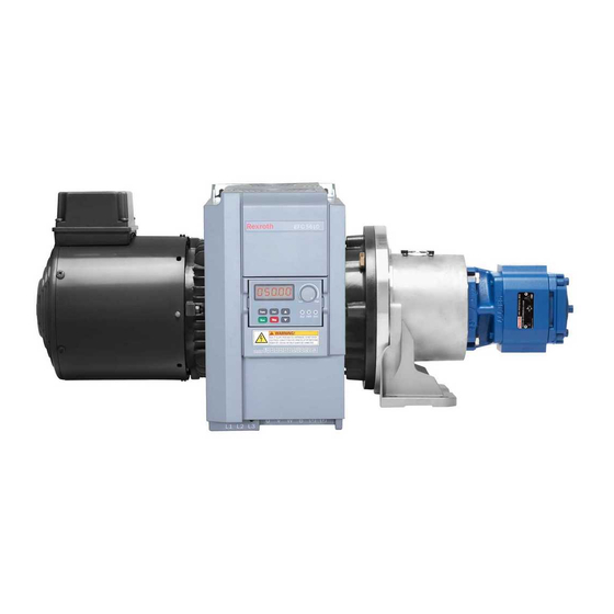
- Page 1 Sytronix FcP 5020 Frequency-Controlled Pump Drive System Quick Start Guide Edition 04 R912006684...
- Page 2 Copyright © Bosch Rexroth (Xi'an) Electric Drives and Controls Co., Ltd. 2018 All rights reserved, also regarding any disposal, exploitation, reproduction, edit- ing, distribution, as well as in the event of applications for industrial property rights.
-
Page 3: Table Of Contents
FcP 5020 Bosch Rexroth AG Table of Contents Table of Contents Page Type Code....................1 Frequency Converter Type Code Description........FcP 5020 ASF Type Code Description........... Scope of Supply..................4 Documentation Reference ..............Function Specification................5 Initial Start Up..................Electric Connection................ - Page 4 Bosch Rexroth AG FcP 5020 Table of Contents Page 7.10.1 Overview....................44 7.10.2 Pressure Sensor Failure Detection............44 7.10.3 Actual Pressure Monitoring..............48 7.10.4 Oil Change Warning / Error Function........... 49 7.10.5 Pressure and Flow Command Limit............. 50 7.10.6 Pump Thermal Protection..............
-
Page 5: Type Code
FcP 5020 Bosch Rexroth AG Type Code 1 Type Code 1.1 Frequency Converter Type Code Description Fig. 1-1: EFC 5610 type code This type code can be found on the Rexroth EFC converter. "Specific variant" in type code of EFC for Sytronix has been updated from C10NN to FCPNN since September of 2017. -
Page 6: Fcp 5020 Asf Type Code Description
Bosch Rexroth AG FcP 5020 Type Code 1.2 FcP 5020 ASF Type Code Description Fig. 1-2: FcP 5020 ASF type code FcP 5020 ASF software material number: R912006662 FcP 5020 ASF software type code: FWS-XFC01*-C10-01VRS-NN ASF: Application Specific Firmware. The ASF type code will not be printed and placed on the EFC converter, but only... - Page 7 FcP 5020 Bosch Rexroth AG Type Code Parameter Name Value F0.01 ASF version F0.02 ASF identifier 0x0C10 F0.03 ASF API required version F0.06 ASF evaluation time F0.07 ASF API version Bit0: ASF valid Bit1: API compatible Bit2: ASF certified Bit3…Bit7: Reserved Bit8: ASF evaluation period expired F0.10...
-
Page 8: Scope Of Supply
Documentation Reference 2 Scope of Supply If any item is found missing from standard supply package as listed below, please contact Bosch Rexroth's local sales partner at your earliest convenience. Frequency Converter EFC 5610 with integrated Sytronix software ● Safety Instructions (available in multiple languages) ●... -
Page 9: Function Specification
FcP 5020 Bosch Rexroth AG Function Specification 4 Function Specification FcP 5020 ASF is developed based on the EFC 5610 hardware platform to be used for pressure and flow control. FcP 5020 has the functionality to automatic switch between pressure and flow mode. The typical application is shown as be- low. - Page 10 Bosch Rexroth AG FcP 5020 Function Specification * Supported communication protocols: Profibus, CANopen, SercosIII, Multi- Ethernet, Modbus. Pressure signal feedback ● – Compatible with different types of pressure sensors (unlimited scaling for the analog input signal) – High resistance capability to electromagnetic interference (with the use of high precision digital filter device for signal filtering) –...
-
Page 11: Initial Start Up
FcP 5020 Bosch Rexroth AG Initial Start Up 5 Initial Start Up After the electric hydraulic system has been correctly assembled, users can take following steps for initial start up. 1. Select pressure sensor via F2.10 (for option ''0: Others", please set F2.06, F2.07 manually). - Page 12 Bosch Rexroth AG FcP 5020 Initial Start Up Code Name Setting range Default Min. Attri. 0: Depend on the value of F1.14 1: Analog input (positive / nega- tive) F1.11 Flow command source Stop 2: Communication 3: Select by digital input (F1.14 shows status) F1.12 Flow command digital setting 0 0...5,000 rpm...
- Page 13 FcP 5020 Bosch Rexroth AG Initial Start Up Code Name Setting range Default Min. Attri. 0: No selection 1: CytroPac basic F1.21 CytroPac parameter display 2: CytroPac advanced Stop 3: CytroPac premium 4: myCro Pressure feedback correspond- F2.06 0.1...1,000.0 bar 100.0...
-
Page 14: Electric Connection
Bosch Rexroth AG FcP 5020 Electric Connection 6 Electric Connection 6.1 Overview Fig. 6-1: Wiring Diagram FcP 5020 I/O functionality is given higher priority over the stand- ● ard EFC functions. The standard EFC functionality assigned to ter- minal will be ignored and taken over by the ASF terminal assign- ment (non-zero entries in ASF). -
Page 15: Analog Input
FcP 5020 Bosch Rexroth AG Electric Connection 6.2 Analog Input This section shows how analog input can be configured. The following figure is an example for analog input AI2, which has been assigned to pressure feedback. The configuration for AI1, EAI and EAI2 is similar to AI2, only with different pa- rameters shown in the table below. - Page 16 Bosch Rexroth AG FcP 5020 Electric Connection Code Name Setting Range Default Min. Attri. F2.00 Analog input AI1 Stop 0: No function assigned from ASF F2.01 Analog input AI2 Stop 1: Pressure command External analog input EAI 2: Pressure feedback F2.02...
- Page 17 FcP 5020 Bosch Rexroth AG Electric Connection CAUTION Setting more than one input to same function is not allowed, by doing this the very last change will be keep, but other conflicted parameter will be set to 0. For example, by setting F2.00=1 and then F2.01=1, the value of F2.00 will be reset to 0 automatically.
-
Page 18: Analog Output
Bosch Rexroth AG FcP 5020 Electric Connection 6.3 Analog Output This section shows how analog output can be configured. The following figure is an example for analog output AO1. The configuration for EAO is similar to AO1, only with different parameters shown in the table below. -
Page 19: Motor Temperature Thermal Protection
FcP 5020 Bosch Rexroth AG Electric Connection Code Name Setting Range Default Min. Attri. F2.31 AO1 output 0: No function assigned from ASF 1: Pressure command (scaled by F2.04) 2: Pressure feedback (scaled by F2.06) F2.32 EAO output 3: Setting speed (include direc- tion) (scaled by F2.08) -
Page 20: Digital Input
Bosch Rexroth AG FcP 5020 Electric Connection 6.5 Digital Input Code Name Setting Range Default Min. Attri. 0: No function assigned from ASF F2.16 X1 input Stop 1: Pressure command selection bit0 (RUN) 2: Pressure command selection bit1 F2.17 X2 input... - Page 21 FcP 5020 Bosch Rexroth AG Electric Connection CAUTION Setting more than one input to same function is not allowed, by doing this the very last change will be keep, but other conflicted parameter will be set to 0. For example, by setting F2.19=2 and then F2.20=2, the value of F2.19 will be reset to 0 automatically.
-
Page 22: Digital And Relay Output
Bosch Rexroth AG FcP 5020 Electric Connection 6.6 Digital and Relay Output Code Name Setting Range Default Min. Attri. F2.36 DO1 output 0: No function assigned from ASF 1: Converter warning 2: Green CytroPac flashing LED F2.37 EDO output 3: Red CytroPac flashing LED... -
Page 23: Block Diagram Of Main Functions
FcP 5020 Bosch Rexroth AG Block Diagram of Main Functions 7 Block Diagram of Main Functions 7.1 Overview The following figure shows an overview of control functions in this ASF, for de- tails information, reference the chapter number which is shown under each function. -
Page 24: Flow Command Processing
Bosch Rexroth AG FcP 5020 Block Diagram of Main Functions 7.2 Flow Command Processing Parameter F1.11 defines the source of flow command. The flow command value can come from either predefined FcP 5020 parameters, analog input or using fieldbus communication. - Page 25 FcP 5020 Bosch Rexroth AG Block Diagram of Main Functions Code Name Setting range Default Min. Attri. F4.20 p/Q command soft start delay 0.0...1,000.0 s Stop F4.23 Minimum flow command limit 0...[F4.24] rpm Stop F4.24 Maximum flow command limit [F4.23]...5,000 rpm...
-
Page 26: Pressure Command Processing
Bosch Rexroth AG FcP 5020 Block Diagram of Main Functions 7.3 Pressure Command Processing Pressure command can be generated from multiple sources such as predefined in the parameters, analog input or fieldbus communication. User needs to define the pressure command source prior to start up the system. - Page 27 FcP 5020 Bosch Rexroth AG Block Diagram of Main Functions Code Name Setting range Default Min. Attri. F2.00 Analog input AI1 0: No function assigned from Stop F2.01 Analog input AI2 Stop 1: Pressure command External analog input EAI (-10V...10V, F2.02...
-
Page 28: Pressure Feedback Input
Bosch Rexroth AG FcP 5020 Block Diagram of Main Functions 7.4 Pressure Feedback Input AI2 input is predefined as the pressure sensor input. User can select a different type of pressure sensor and scaling factor. In case of Rexroth HM20 pressure sensor is used the parameter F2.10 use for setting the installed HM20 pressure... -
Page 29: Quick Configuration For Rexroth Hm20 Pressure Sensor
FcP 5020 Bosch Rexroth AG Block Diagram of Main Functions 7.5 Quick Configuration For Rexroth HM20 Pressure Sensor For application using Rexroth HM20 pressure transducer, configuration parame- ters of HM20 sensor can be automatically loaded by selecting the corresponding type code in parameter F2.10. Please make sure the right analog input channel has been set through [F2.00]...[F2.02] before setting [F2.10], since the configu-... - Page 30 Bosch Rexroth AG FcP 5020 Block Diagram of Main Functions Name Setting range Default Min. Attri. Code Pressure feedback null offset F2.07 0.0...5.0 V, mA Stop in V or mA (mA) 0: Others 1: HM20-2X/10-C 2: HM20-2X/50-C 3: HM20-2X/100-C 4: HM20-2X/160-C...
-
Page 31: Quick Configuration For Rexroth Mot-Fc_Hoy Motor
FcP 5020 Bosch Rexroth AG Block Diagram of Main Functions 7.6 Quick Configuration For Rexroth MOT-FC_HOY Motor When MOT-FC_HOY motor is used with FcP 5020 ASF application, saved motor parameters can be loaded via F1.15 and F1.16. Please keep [F1.15]=1 for MOT- FC_HOY motor, for third part motor please set [F1.15]=0 and set the motor pa-... - Page 32 Bosch Rexroth AG FcP 5020 Block Diagram of Main Functions Code Name Code Name C1.05 Motor rated power C1.21 Stator resistance C1.06 Motor rated voltage C1.22 Rotor resistance C1.07 Motor rated current C1.23 Leakage inductance C1.08 Motor rated frequency C1.24 Mutual inductance Motor thermal model protection time C1.09 Motor rated speed...
-
Page 33: P/Q Pid Control
FcP 5020 Bosch Rexroth AG Block Diagram of Main Functions 7.7 p/Q PID Control Fig. 7-8: p/Q PID control Code Name Setting range Default Min. Attri. F3.12 Proportional gain [0] 0.00...500.00 rpm/bar 8.00 0.01 F3.13 Integral time 1 [0] 0...999 ms F3.14 Integral time 2 [0]... - Page 34 Bosch Rexroth AG FcP 5020 Block Diagram of Main Functions Code Name Setting range Default Min. Attri. 0: Depend on the value of F3.01 F3.00 p/Q parameter selection source 1: Digital input (F3.01 Stop shows status) 2: Communication 0: Parameter group 0 F3.01 p/Q parameter digital selection...
- Page 35 FcP 5020 Bosch Rexroth AG Block Diagram of Main Functions Code Name Setting range Default Min. Attri. F3.13 Integral time 1 [0] 0...999 ms F3.14 Integral time 2 [0] 0...999 ms -150.0...0.0 bar (the switch- Integral time TI switch thresh- F3.15...
- Page 36 Bosch Rexroth AG FcP 5020 Block Diagram of Main Functions quency oscillation at differential stage. However excessively large setting the fil- ter time would cause delay of pressure response. Code Name Setting range Default Min. Attri. F3.18 Lower limit for I+D [0] -5,000…5,000 rpm...
-
Page 37: Restore Asf Parameter
FcP 5020 Bosch Rexroth AG Block Diagram of Main Functions 7.8 Restore ASF Parameter User can restore ASF parameter setting to default via F1.00, by doing this follow- ing EFC parameters will be re-set to ASF default values as well. Please reference chapter 8.6 "Auto-modified EFC Parameters in FcP Initialization"... -
Page 38: Extension Functions
Bosch Rexroth AG FcP 5020 Block Diagram of Main Functions 7.9 Extension Functions 7.9.1 Master / Slave Function Master / slave pump function is designed for multi-pump working as a group to achieve a larger flow. In this application, a master converter is needed to control the speed / flow of slave pumps. - Page 39 FcP 5020 Bosch Rexroth AG Block Diagram of Main Functions Code Name Setting range Default Min. Attri. 0: Depend on the value of F4.03 F4.39 Master / slave switch source 1: Digital input Stop 2: Communication Slave pump speed command F4.40...
-
Page 40: Sleep / Wake Function
Bosch Rexroth AG FcP 5020 Block Diagram of Main Functions 7.9.2 Sleep / Wake Function This function is used to achieve the maximum extent of energy-saving according to the type of loads in actual applications, for example hydraulic system with small leakage or accumulator. - Page 41 FcP 5020 Bosch Rexroth AG Block Diagram of Main Functions Fig. 7-13: Sleep and wake up process in FcP After [E5.16] ''Sleep delay'', the PID controller boosts up with [E5.18] ''Sleep boost amplitude'' within [E5.17] ''Sleep boost time'', and then enters to sleep mode.
-
Page 42: Two Points / Double Pump Control
Bosch Rexroth AG FcP 5020 Block Diagram of Main Functions 7.9.3 Two Points / Double Pump Control Code Name Setting range Default Min. Attri. F2.40 Relay 1 output 0: No function assigned from ASF 1: Converter warning F2.41 Extension relay output 2: Two points / double pump control 0...63... - Page 43 FcP 5020 Bosch Rexroth AG Block Diagram of Main Functions Please refer to the figure below for pump switching logic (F4.28 = 0, F4.29 = 0). This pump switching logic can also be inversed via F4.29 or different terminal connecting from relay. Effective Vg F4.38 will be calculated according to this switching logic, this is a read only parameter.
-
Page 44: Pressure Drop / Overshoot Compensation
Bosch Rexroth AG FcP 5020 Block Diagram of Main Functions 7.9.4 Pressure Drop / Overshoot Compensation Pressure drop / overshoot compensation function helps to compensate the in- coming pressure drop or overshoot by previously changing pressure command with digital from customer PLC. - Page 45 FcP 5020 Bosch Rexroth AG Block Diagram of Main Functions Fig. 7-15: F4.45: Pressure boost for drop compensation Fig. 7-16: F4.46: Pressure reduce for overshoot compensation 41/83 DOK-RCON03-FCP5020****-QU04-EN-P...
-
Page 46: Pump Power Limitation
Bosch Rexroth AG FcP 5020 Block Diagram of Main Functions 7.9.5 Pump Power Limitation Code Name Setting range Default Min. Attri. 0...63 Bit0: Pump power limit Bit1: Pump thermal protection Pump function F4.03 configuration Bit2: Switch master to slave Stop... -
Page 47: Hydraulic Soft Start With Separate Acceleration Ramp
FcP 5020 Bosch Rexroth AG Block Diagram of Main Functions 7.9.6 Hydraulic Soft Start with Separate Acceleration Ramp Code Name Setting range Default Min. Attri. F4.20 p/Q command soft start delay 0.0...1,000.0 s Stop F4.21 Minimum pressure command limit 0.0...[F4.22] bar Stop F4.23 Minimum flow command limit... -
Page 48: Protection Function
Bosch Rexroth AG FcP 5020 Block Diagram of Main Functions 7.10 Protection Function 7.10.1 Overview FcP 5020 ASF provides a multiple of protection functions, including detection of pressure sensor failure, actual pressure monitoring, pressure / flow command monitoring, pump power limitation and so on. - Page 49 FcP 5020 Bosch Rexroth AG Block Diagram of Main Functions The pressure sensor failure detection works in three different phases: Motor runs in negative direction ● Once motor runs in negative direction, this function will check if the motor speed is consistently lower than [F4.06] for [F4.07] seconds and signal a fail- ure for this.
- Page 50 Bosch Rexroth AG FcP 5020 Block Diagram of Main Functions Motor runs in positive direction ● Once motor runs in positive direction with the speed higher than [F4.08], this function will check if the pressure feedback is consistently lower than 0.5 bar for [F4.09] seconds and signal a failure for this.
- Page 51 FcP 5020 Bosch Rexroth AG Block Diagram of Main Functions Motor stops ● If the motor stops and the feedback pressure is higher than [F4.10], the de- tection function will check if the system pressure feedback keeps dropping with decreasing rate higher than 1/[F4.11] bar/s, if the pressure drops slower than this rate consistently for 2x[F4.11] seconds, a failure for sensor defect...
-
Page 52: Actual Pressure Monitoring
Bosch Rexroth AG FcP 5020 Block Diagram of Main Functions 7.10.3 Actual Pressure Monitoring Code Name Setting range Default Min. Attri. 0...15 Bit0: Pressure sensor fail- ure (PSF) Protection function configuration Bit1: Actual pressure moni- F4.00 word toring Bit2: p/Q max. command... -
Page 53: Oil Change Warning / Error Function
FcP 5020 Bosch Rexroth AG Block Diagram of Main Functions Fig. 7-22: F4.16 maximum pump pressure failure Actual pressure monitoring function works all the time, no matter when drive is in operation or standby. 7.10.4 Oil Change Warning / Error Function... -
Page 54: Pressure And Flow Command Limit
Bosch Rexroth AG FcP 5020 Block Diagram of Main Functions 7.10.5 Pressure and Flow Command Limit Code Name Setting range Default Min. Attri. 0...15 Bit0: Pressure sensor failure (PSF) Protection function configura- F4.00 Bit1: Actual pressure monitoring tion word Bit2: p/Q max. command limit... -
Page 55: Pump Thermal Protection
FcP 5020 Bosch Rexroth AG Block Diagram of Main Functions 7.10.6 Pump Thermal Protection Code Name Setting range Default Min. Attri. 0...63 Bit0: Pump power limit Bit1: Pump thermal protection Bit2: Switch master to slave F4.03 Pump function configuration word... -
Page 56: Sensor Monitoring
Bosch Rexroth AG FcP 5020 Block Diagram of Main Functions 7.10.7 Sensor Monitoring Code Name Setting range Default Attri. F2.16 X1 input 0: No function assigned from ASF Stop F2.17 X2 input Stop 1: Pressure command selection bit0 F2.18 X3 input... - Page 57 FcP 5020 Bosch Rexroth AG Block Diagram of Main Functions troller to determine if it is an ''oil level error'', ''oil temperature error'' or even ''oil level or temperature error'' if both or no warning is available. ''13: Oil level warning inverse'' and ''14: Oil level / temperature error inverse'' are inversed evaluation from ''7: Oil level warning'' and ''12: Oil level / temperature error'', i.e.
-
Page 58: Cytropac Configuration
Block Diagram of Main Functions 7.11 CytroPac Configuration 7.11.1 Overview CytroPac is a variation of Bosch Rexroth hydraulic system similar to FcP func- tionalities. To support easy use of CytroPac, the FcP 5020 ASF provides quick way to configure predefined CytroPac applications. -
Page 59: Led Flash Showing Converter Status
FcP 5020 Bosch Rexroth AG Block Diagram of Main Functions 7.11.3 LED Flash Showing Converter Status Code Name Setting range Default Attri. F2.36 DO1 output 0: No function assigned from ASF 1: Converter warning 2: Green CytroPac flashing LED F2.37 EDO output... - Page 60 Bosch Rexroth AG FcP 5020 Block Diagram of Main Functions Fig. 7-24: LED flash function 56/83 DOK-RCON03-FCP5020****-QU04-EN-P...
-
Page 61: Mycro Configuration
7.12.1 Overview myCro is a function package based on FcP system, for controlling a hydraulic ex- haust device by Bosch Rexroth called "myCro", which controls speed variable pump to adjust hydraulic fluid in constant pressure for gas exhausting. myCro swithes pump on / off for degassing automatically according to gas content feedback. - Page 62 Bosch Rexroth AG FcP 5020 Block Diagram of Main Functions myCro Code Name Setting range default default 0: No selection 1: CytroPac basic F1.21 CytroPac parameter display 2: CytroPac advanced 3: CytroPac premium 4: myCro F2.00 Analog input AI1 0: No function assigned from ASF F2.01 Analog input AI2...
- Page 63 FcP 5020 Bosch Rexroth AG Block Diagram of Main Functions myCro Code Name Setting range default default F2.36 DO1 output 0: No function assigned from ASF 1: Converter warning 2: Green CytroPac flashing LED F2.37 EDO output 3: Red CytroPac flashing LED...
- Page 64 Bosch Rexroth AG FcP 5020 Block Diagram of Main Functions myCro Code Name Setting range default default Pressure too low warning F4.74 0.0...300.0 bar 100.0 100.0 level Pressure too low warning F4.75 0.0...100.0 s 60.0 60.0 delay 0...10: See tab. 8-6 "Monitoring pa- rameter"...
-
Page 65: Mycro Function Description
FcP 5020 Bosch Rexroth AG Block Diagram of Main Functions 7.12.3 myCro Function Description Drive enables via both digital input and analog input together ● The drive can be started only if both digital and analog input are available: For digital input, select one of them to "22: Enable for myCro"... -
Page 66: Fcp 5020 Parameter List
Bosch Rexroth AG FcP 5020 FcP 5020 Parameter List 8 FcP 5020 Parameter List 8.1 Terminology and Abbreviation in Parameter List Code: Function / parameter code, written in Cx.xx, dx.xx, Ex.xx, Fx.xx ● Name: Parameter name ● Default: Factory default ●... -
Page 67: Group F1: Quick Start Parameter
FcP 5020 Bosch Rexroth AG FcP 5020 Parameter List 8.2 Group F1: Quick Start Parameter Code Name Setting range Default Min. Attri. 0: Inactive 1: Restore to FcP default set- F1.00 ASF parameter initialization Stop tings 2: Deactivate ASF 0: p/Q control F1.02 Control mode... - Page 68 Bosch Rexroth AG FcP 5020 FcP 5020 Parameter List Code Name Setting range Default Min. Attri. F1.13 Flow command digital setting 1 0...5,000 rpm 0:Flow command digital set- ting 0 F1.14 Flow command selection 1:Flow command digital set- ting 1 0: Others F1.15 Motor type...
- Page 69 FcP 5020 Bosch Rexroth AG FcP 5020 Parameter List Code Name Setting range Default Min. Attri. 0: No selection 1: CytroPac basic CytroPac parameter initializa- F1.20 2: CytroPac advanced Stop tion 3: CytroPac premium 4: myCro 0: No selection 1: CytroPac basic F1.21 CytroPac parameter display...
-
Page 70: Group F2: Input And Output Parameter
Bosch Rexroth AG FcP 5020 FcP 5020 Parameter List 8.3 Group F2: Input and Output Parameter Code Name Setting range Default Min. Attri. F2.00 Analog input AI1 Stop 0: No function assigned from ASF F2.01 Analog input AI2 Stop 1: Pressure command... - Page 71 FcP 5020 Bosch Rexroth AG FcP 5020 Parameter List Code Name Setting range Default Min. Attri. 0: Others 1: HM20-2X/10-C 2: HM20-2X/50-C 3: HM20-2X/100-C 4: HM20-2X/160-C 5: HM20-2X/250-C 6: HM20-2X/315-C 7: HM20-2X/400-C 8: HM20-2X/630-C 9: Other 4...20 mA pressure sensor F2.10 Pressure sensor type...
- Page 72 Bosch Rexroth AG FcP 5020 FcP 5020 Parameter List Code Name Setting range Default Min. Attri. 0: No function assigned from ASF F2.16 X1 input Stop 1: Pressure command selection bit0 (RUN) 2: Pressure command selection bit1 F2.17 X2 input...
- Page 73 FcP 5020 Bosch Rexroth AG FcP 5020 Parameter List Code Name Setting range Default Min. Attri. F2.36 DO1 output 0: No function assigned from ASF 1: Converter warning 2: Green CytroPac flashing LED F2.37 EDO output 3: Red CytroPac flashing LED...
-
Page 74: Group F3: P/Q Pid Parameter
Bosch Rexroth AG FcP 5020 FcP 5020 Parameter List 8.4 Group F3: p/Q PID Parameter Code Name Setting range Default Min. Attri. 0: Depend on the value of F3.01 1: Digital input (F3.01 shows sta- F3.00 p/Q parameter selection source... -
Page 75: Group F4: System Protection And Pump Function Parameter
FcP 5020 Bosch Rexroth AG FcP 5020 Parameter List 8.5 Group F4: System Protection and Pump Function Parameter Code Name Setting range Default Min. Attri. 0...15 Bit0: Pressure sensor failure (PSF) Protection function configuration Bit1: Actual pressure moni- F4.00 word toring Bit2: p/Q max. - Page 76 Bosch Rexroth AG FcP 5020 FcP 5020 Parameter List Code Name Setting range Default Min. Attri. F4.21 Minimum pressure command limit 0.0...[F4.22] bar Stop Maximum pressure command lim- F4.22 [F4.21]...1,000.0 bar 250.0 Stop F4.23 Minimum flow command limit 0...[F4.24] rpm Stop F4.24 Maximum flow command limit...
- Page 77 FcP 5020 Bosch Rexroth AG FcP 5020 Parameter List Code Name Setting range Default Min. Attri. F4.53 Oil in operation time 0...60,000 hours Read F4.54 Reset oil in operation time 0...1 F4.70 Drive start level via AI (for myCro) 0.0...20.0 V, mA 14.2...
-
Page 78: Auto-Modified Efc Parameters In Fcp Initialization
Bosch Rexroth AG FcP 5020 FcP 5020 Parameter List 8.6 Auto-modified EFC Parameters in FcP Initialization Code Name Setting range Default Min. Attri. E0.01 First run command source 0...2 Stop E0.02 Second frequency setting source 0...99 Stop E0.08 Maximum output frequency 50.00...400.00 Hz... -
Page 79: Monitoring Parameter
FcP 5020 Bosch Rexroth AG FcP 5020 Parameter List 8.7 Monitoring Parameter Name Description Setting range d0.80 ASF status word * 0x0000...0xFFFF d0.81 Pressure command 0.0...1,000.0 (0.0...1,000.0 bar) d0.82 Pressure feedback 0.0...1,000.0 (0.0...1,000.0 bar) d0.83 Flow command -5,000...5,000 (-5,000...5,000 rpm) d0.84 Effective speed command... -
Page 80: Fieldbus Communication
Bosch Rexroth AG FcP 5020 Fieldbus Communication 9 Fieldbus Communication 9.1 Brief Introduction FcP 5020 frequency converter provides standard communication interface to re- alize the communication between the master and slave via Modbus, Profibus, Profinet, CANopen, Ethernet and other protocols. With the help of a PC, a PLC... - Page 81 FcP 5020 Bosch Rexroth AG Fieldbus Communication Description Setting range 0: Master Master / slave selection 1: Slave 0: Parameter group 0 p/Q parameter group selection 1: Parameter group 1 Reserved Reserved Reserved Reserved Reserved Reserved Reserved Reserved Reserved Reserved...
- Page 82 Bosch Rexroth AG FcP 5020 Fieldbus Communication Description Setting range 0: No compensation Pressure drop / overshoot com- pensation 1: Compensation 0: Pressure deviation bigger than tolerance window Pressure command arrived 1: Pressure deviation within tolerance window 0: Active ASF status...
-
Page 83: Diagnosis
FcP 5020 Bosch Rexroth AG Diagnosis 10 Diagnosis 10.1 Warning Code Panel Function Error information Reason Solution display code 0: No warning 1. Set pressure to a lower value 1. Excessive pressure setting 1: Pressure feed- 2. Check if the wiring is proper- back exceed limit 2. -
Page 84: Error Code
Bosch Rexroth AG FcP 5020 Diagnosis 10.2 Error Code Panel Function Error information Reason Solution display code 0: No error 1. Set pressure to a lower val- 1: Pressure feed- Actual pressure exceeding 2. Check if the wiring is prop- back exceed pump [F4.16] (pump maximum... -
Page 85: Index
FcP 5020 Bosch Rexroth AG Index Index Actual Pressure Monitoring... 48 Initial Start Up........ 7 Analog Input AI2......11 Input and Output Parameter..66 Analog Output....... 14 Auto-modified EFC Parame- ters in FcP Initialization....74 LED Flash Showing Converter Sta- tus.......... - Page 86 Bosch Rexroth AG FcP 5020 Index Scope of Supply......4 Sensor Monitoring......52 Sleep / Wake Function....36 System Protection and Pump Function Parameter...... 71 Terminology and Abbreviation in Parameter List......62 Two Points / Double Pump Con- trol..........38 Type Code........
- Page 87 FcP 5020 Bosch Rexroth AG Notes...
- Page 88 Bosch Rexroth AG Electric Drives and Controls P.O. Box 13 57 97803 Lohr, Germany Bgm.-Dr.-Nebel-Str. 2 97816 Lohr, Germany Phone +49 9352 18 0 Fax +49 9352 18 8400 www.boschrexroth.com/electrics *R912006684* R912006684 DOK-RCON03-FCP5020****-QU04-EN-P...