Dynojet POWER COMMANDER V Installation Instructions
Fuel management device
Hide thumbs
Also See for POWER COMMANDER V:
- Installation instructions manual (9 pages) ,
- Installation manual (9 pages) ,
- Installation instructions and owner's manuals (8 pages)
Quick Links
2006-2007 Kawasaki ZX-10R
I n s t a l l a t i o n I n s t r u c t i o n s
PLEASE READ ALL DIRECTIONS BEFORE STARTING INSTALLATION
17-027
www.powercommander.com
2191 Mendenhall Drive North Las Vegas, NV 89081 (800) 992-4993 www.powercommander.com
PARTS LIST
1
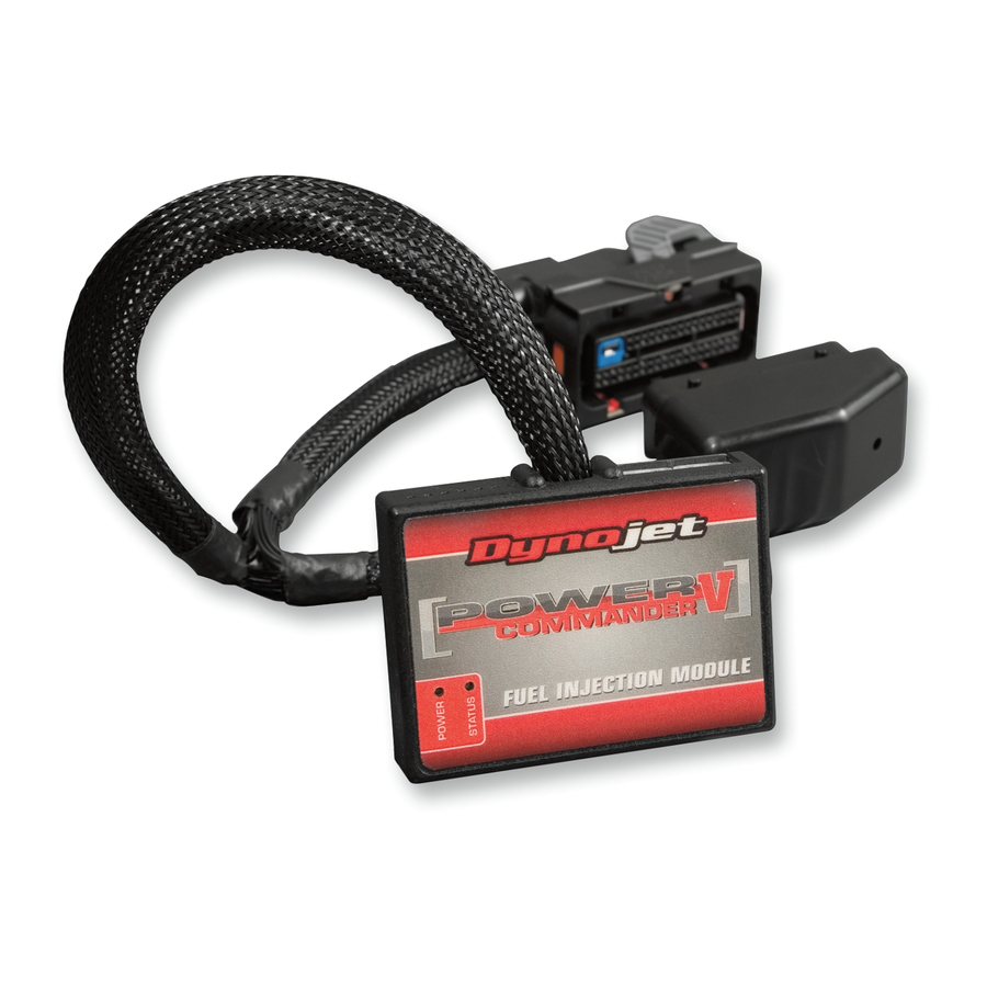
Power Commander
1
USB Cable
1
CD-ROM
1
Installation Guide
2
Power Commander Decals
2
Dynojet Decals
2
Velcro
1
Alcohol swab
THE IGNITION MUST BE TURNED
OFF BEFORE INSTALLATION!
YOU CAN ALSO DOWNLOAD THE
POWER COMMANDER SOFTWARE AND
LATEST MAPS FROM OUR WEB SITE AT:
www.powercommander.com
2006-2007 Kawasaki ZX-10R - PCV - 1

Related Manuals for Dynojet POWER COMMANDER V


Summary of Contents for Dynojet POWER COMMANDER V
- Page 1 2006-2007 Kawasaki ZX-10R Installation Guide Power Commander Decals I n s t a l l a t i o n I n s t r u c t i o n s Dynojet Decals Velcro Alcohol swab THE IGNITION MUST BE TURNED OFF BEFORE INSTALLATION!
- Page 2 Do NOT connect anything to this port unless wire into the hole of the PCV until is stops and then instructed to do so by Dynojet. It is used to tighten the screw. Make sure to reinstall the rubber transfer crank trigger data from one module to plug.
- Page 3 FIG.A Remove the main seat and the passenger seat. Place the PCV module in the tail section and route the wiring harness on the inside of the tail section towards the front of the bike (Fig. A). FIG.B Unbolt the front of the fuel tank and prop it up. Route the PCV harness down the left hand side of the bike going beneath the fuel tank bracket (Fig. B). FIG.C Locate and unplug the sub-harness connector for the bike’s fuel rail (Fig. C). This is a 16-pin BROWN connector on the right hand side of the bike under Unplug the fuel tank and behind the engine. 17-027 www.powercommander.com 2006-2007 Kawasaki ZX-10R - PCV - 3...
- Page 4 FIG.D Plug the pair of PCV connectors in-line of the stock connectors (Fig. D). Secure the PCV ground wire with the ring lug to the negative terminal of the FIG.E bike’s battery. Use the supplied Velcro to secure the PCV module in the tail section (Fig. E). Clean the surface area with the supplied alcohol swab prior to applying the Velcro. Secure the front of the fuel tank and reinstall the seats. Optional Inputs: Speed - BLUE/YELLOW wire. Senor is located on the left hand side of the engine case in front of the countershaft sprocket. Temperature - BLUE/WHITE wire on the GREY 10-pin connector under the fuel tank. 12v source for Auto-tune - RED wire of the taillight connector. 17-027 www.powercommander.com 2006-2007 Kawasaki ZX-10R - PCV - 4...