Emerson 2120 Quick Start Manual
Level switch
Hide thumbs
Also See for 2120:
- Reference manual (82 pages) ,
- Quick start manual (40 pages) ,
- Manual supplement (16 pages)
Table of Contents
Quick Links
See also:
Reference Manual
Table of Contents

Related Manuals for Emerson 2120


Summary of Contents for Emerson 2120
- Page 1 Quick Start Guide 00825-0100-4030, Rev FA December 2016 ™ Rosemount 2120 Level Switch Vibrating Fork...
- Page 2 December 2016 Quick Start Guide NOTICE This guide provides basic guidelines for Rosemount 2120 Level Switch. It does not provide instructions for configuration, diagnostics, maintenance, service, troubleshooting, or intrinsically safe (I.S.) installations. Refer to the Rosemount 2120 Reference Manual for more instruction. The manual and this guide are also available electronically on Emerson.com/Rosemount.
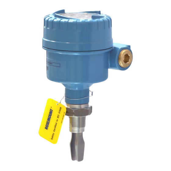
- Page 3 1.0 Introduction 1.1 Rosemount 2120 overview The Rosemount 2120 Level Switch (“level switch”) uses vibrating short fork technology, and is suitable for virtually all liquid applications. The level switch is designed to use the principle of a tuning fork. A piezo-electric crystal oscillates the forks at their natural frequency (~1400 Hz).
-
Page 4: Before Installation
“Product Certifications” on page 15 for hazardous area and hygienic installation requirements. The weight of the Rosemount 2120 Level Switch (“level switch”) with a heavy flange and extended fork length may exceed 37 lb. (18 kg). A risk assessment is required to be done before carrying, lifting, and installing the level switch. -
Page 5: Physical Installation
(Figure 2. Use supports for extended fork lengths greater than 3.2 ft. (1 m). Refer to the Rosemount 2120 Reference Manual for guidance. 3. Close the housing cover and tighten to safety specification. Always ensure a proper seal so that metal touches metal or plastic touches plastic, but do not over tighten. - Page 6 December 2016 Quick Start Guide Figure 5. Example Installations Threaded installation Flanged installation See the Rosemount 2120 Quick Release Kit Quick Start Guide Tri Clamp installation general Tri Clamp installation instructions. See also “Instructions for hygienic installations” on page 26 hygienic installation requirements.
-
Page 7: Electrical Installation
Quick Start Guide December 2016 4.0 Electrical installation Before use, check that suitable cable glands and blanking plugs are fitted and fully tightened. Isolate supply before connecting the switch or removing the electronics. The functional earth terminal must be connected to an external earthing system. - Page 8 December 2016 Quick Start Guide 4.2 PNP/PLC switching electronics (yellow label) PLC/PNP OPERATION MODE Dry On Mode Dry On Wet On Isolate Supply Before Removing Seconds Delay Wet On Mode ) = 0 - 500 mA U = 20 - 60 V (dc) I <...
- Page 9 Quick Start Guide December 2016 4.3 DPCO relay output electronics (green label, standard version) OPERATION MODE Warning Isolate Supply Before Removing Seconds Delay Dry On Dry On Wet On Wet On Fuse 0.5 (T) Resistive Load Inductive Load (Ground) cos φ = 1 ; cos φ...
- Page 10 December 2016 Quick Start Guide 4.4 DPCO relay output electronics (green label, 12 Vdc nominal version) 12 VDC NOM. Isolate Supply Before Removing OPERATION MODE Seconds Delay Dry On Dry On Wet On Wet On Fuse 0.5 (T) Resistive Load Inductive Load (Ground) cos φ...
- Page 11 Quick Start Guide December 2016 4.5 NAMUR electronics (light blue label) OPERATION MODE EN 50227 / NAMUR Dry On Wet On Dry On Mode Seconds Delay Wet On Mode = 2.2 ... 2.5 mA = 0.8 ... 1.0 mA < 1.0 mA FAULT A certified intrinsically safe isolating amplifier to IEC 60947-5-6...
- Page 12 December 2016 Quick Start Guide 4.6 8/16 mA electronics cassette (dark blue label) OPERATION MODE Dry On Mode Dry On Wet On 8/16 mA Wet On Mode Seconds Delay 15 ... 17 mA U = 24 Vdc Nominal 7.5 ... 8.5 mA <...
-
Page 13: Verify Operation
1 every second Output state is off Uncalibrated: Refer to the “Replacement and Calibration of Electronic 1 every 2 seconds Cassettes” section in the Rosemount 2120 Reference Manual Manual Supplement 1 every 4 seconds Load fault; load current too high; load short circuit... -
Page 14: Maintenance And Inspection
Ensure the housing cover, cable glands, and blanking plugs are fitted securely. Ensure the LED flash rate is 1 Hz or continually on. (See “LED indication” on page 13). 8.0 Spare parts See the Rosemount 2120 Product Data Sheet for spares and accessories. ... -
Page 15: Troubleshooting
Cassette has been fitted from another Fit the factory supplied cassette and then Rosemount 2120 calibrate 1. Refer to the “Replacement and Calibration of Electronic Cassettes” section in the Rosemount 2120 Reference Manual Manual Supplement. 10.0 Product Certifications 10.1 European Union directive information... - Page 16 ASME B16.5 flanged process connections. 10.9 Safety Integrity Level (SIL) certification The Rosemount 2120 has been independently certified to IEC 61508 as required by IEC 61511. Certification was conducted by Exida. The Rosemount 2120 is SIL2-certified, and is SIL3 capable.
- Page 17 Quick Start Guide December 2016 North American and Canadian approvals Factory Mutual (FM) explosion-proof approval (See “Instructions for hazardous area installations (E5 and E6)” on page E5 Project ID: 3012658 Explosion-proof for Class I, Div. 1, Groups A, B, C, and D Temperature Class: T6 (T –40 to 75 °C) Enclosure: Type 4X...
- Page 18 Class 1, Div 1, Groups A, B, C and D. 2. CSA and FM Explosion Proof approved versions of the 2120 are certified for use in ambient temperatures of –40 °F to 176 °F (–40 °C to 80 °C), and with a maximum process temperature of 302 °F (150 °C).
- Page 19 As this provides a partition wall, it is recommended that the fork should be inspected every 2 years for signs of defects. 9. Technical data: a. Coding: Class 1, Div 1, Groups A, B, C, and D b. Temperature: 2120*****E5Y**, 2120*****E5T**, 2120*****E6Y**, 2120*****E6T** Temperature Maximum ambient air Maximum process classes...
- Page 20 (“*” indicates options in construction, function and materials.) The following instructions apply to equipment covered by FM and CSA approvals: 1. The intrinsically safe approved Rosemount 2120 may be used in hazardous locations with flammable gases and vapors Class 1 Division 1 Groups A, B, C,...
- Page 21 Under certain extreme circumstances, the non-metallic parts incorporated in the enclosure of the Rosemount 2120 may generate an ignition-capable level of electrostatic charge. Therefore, when they are used for applications that specifically require group II equipment, the Rosemount 2120 shall not be installed in a location where the external conditions are conducive to the build-up of electrostatic charge on such surfaces.
- Page 22 December 2016 Quick Start Guide 10.13 Instructions for hazardous area installations (E1 and E7) Model numbers covered: 2120*****E1X**, 2120*****E1S**, 2120*****E7X**, 2120*****E7S** (“*” indicates options in construction, function and materials.) The following instructions apply to the equipment covered by certificates numbered Sira 05ATEX1129X and IECEx SIR 06.0051X...
- Page 23 Minimum ambient air temperature (Ta) = –40°C Minimum process temperature (Tp) = –40°C c. Pressure: Must not exceed the rating of the coupling/flange fitted. d. For electrical details and pressure ratings, see the Rosemount 2120 Product Data Sheet Reference Manual.
- Page 24 Sira 05ATEX2130X and IECEx Sir 06.0070X 1. The Intrinsically Safe approved versions of the 2120 may be used in a hazardous area with explosive gases and vapors with apparatus groups IIC, IIB, and IIA, and with temperature classes T1, T2, T3, T4, and T5 [...
-
Page 25: Technical Data
Suitable precautions – e.g. regular checks as part of routine inspections or establishing from the material’s data sheet that it is resistant to specific chemicals. 7. The Rosemount 2120 meets the requirements of clause 6.3.12 (Isolation of circuits from earth or frame) in EN 60079-11 (IEC 60079-11). 8. Technical data: a. - Page 26 Zone 0 and 20 ATEX: IECEx: locations], the Rosemount 2120 shall not be installed in a location where the external conditions are conducive to the build-up of electrostatic charge on such surfaces. Additionally, the Rosemount 2120 shall only be cleaned with a damp cloth.
- Page 27 Quick Start Guide December 2016 3. Inspection and maintenance of the level switch shall be carried out by suitably trained personnel, in accordance with the applicable standards and code of practice. 4. If the level switch is installed in a stub then, to ensure clean-ability, the length (L) must not exceed the diameter (D) with a minimum diameter of 46 mm.
- Page 28 December 2016 Quick Start Guide Figure 9. EC Declaration of Conformity for Rosemount 2120 (Page 1)
- Page 29 Quick Start Guide December 2016 Figure 10. EC Declaration of Conformity for Rosemount 2120 (Page 2)
- Page 30 December 2016 Quick Start Guide Figure 11. EC Declaration of Conformity for Rosemount 2120 (Page 3)
- Page 31 Quick Start Guide December 2016 Rosemount 2120 China RoHS Rosemount 2120 List of Parts with China RoHS Concentration above MCVs / Hazardous Substances Hexavalent Polybrominated Polybrominated Part Name Lead Mercury Cadmium Chromium biphenyls diphenyl ethers (Pb) (Hg) (Cd) (Cr +6)
- Page 32 [email protected] Standard Terms and Conditions of Sale can be found at www.Emerson.com/en-us/Terms-of-Use Middle East and Africa Regional Office The Emerson logo is a trademark and service mark of Emerson Emerson Automation Solutions Electric Co. Emerson FZE P.O. Box 17033, Rosemount and Rosemount logotype are trademarks of Emerson .