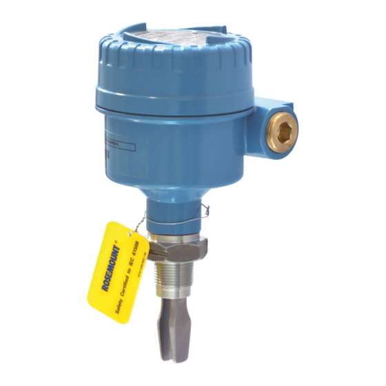
Emerson Rosemount 2120 Reference Manual
Level switch, vibrating fork
Hide thumbs
Also See for Rosemount 2120:
- Reference manual (82 pages) ,
- Quick start manual (40 pages) ,
- Manual supplement (16 pages)

Related Manuals for Emerson Rosemount 2120


Summary of Contents for Emerson Rosemount 2120
- Page 1 Reference Manual 00809-0100-4030, Rev FA December 2016 ™ Rosemount 2120 Level Switch Vibrating Fork...
-
Page 3: Table Of Contents
Reference Manual Contents 00809-0100-4030, Rev FA December 2016 Contents 1Section 1: Introduction Using this manual ..............1 Models covered . - Page 4 Contents Reference Manual 00809-0100-4030, Rev FA December 2016 3Section 3: Service and Troubleshooting Safety messages..............27 Magnetic test point .
- Page 5 The products described in this document are NOT designed for nuclear-qualified applications. Using non-nuclear qualified products in applications that require nuclear-qualified hardware or products may cause inaccurate readings. For information on Rosemount nuclear-qualified products, contact your local Emerson sales representative. Title Page...
- Page 6 Failure to follow these installation guidelines could result in death or serious injury. Make sure only qualified personnel perform the installation. Use the Rosemount 2120 Level Switch (“level switch”) only as specified in this manual. Failure to do so may impair the protection provided by the equipment.
-
Page 7: Using This Manual
EHDEG, and compliant with FDA and ASME-BPE This combination of features makes the Rosemount 2120 Level Switch an ideal choice for a wide variety of challenging applications in the chemical, power generation, and oil and gas industries. Introduction... - Page 8 By selecting the option of direct load switching or relay electronics, the Rosemount 2120 is ideal for reliable pump control and can be used to protect against pumps running dry.
-
Page 9: Measurement Principle
This allows for minimum intrusion into the tank or pipe through the use of a short fork. Using short fork technology, the Rosemount 2120 Level Switch can be used in almost all liquid applications. Extensive research has maximized the operational effectiveness of the fork design, making it suitable for most liquids including coating liquids, aerated liquids, and slurries. -
Page 10: Special Features
Mode switch and adjustable time delay A mode switch allows the Rosemount 2120 to be set to switch from wet to dry (typically for low level alarm) or from dry to wet (typically for high level alarm). There is also a user-selectable time delay (0.3, 1, 3, 10, or 30 s) to virtually eliminate the risk of false switching in turbulent or splashing applications. -
Page 11: Safety Messages
Failure to follow these installation guidelines could result in death or serious injury. Make sure only qualified personnel perform the installation. Use the Rosemount 2120 Level Switch (“level switch”) only as specified in this manual. Failure to do so may impair the protection provided by the equipment. -
Page 12: Considerations Before Installation
Considerations before installation Important Emerson is not in a position to evaluate or guarantee the compatibility of the process fluid or other process parameters with the product, options, configuration or materials of construction selected. 2.2.1 Safety considerations... -
Page 13: Application Considerations
Reference Manual Installation 00809-0100-4030, Rev FA December 2016 2.2.3 Application considerations For most liquids, including coating, aerated liquids and slurries, the function is virtually unaffected by flow, turbulence, bubbles, foam, vibration, solid particles, build-up, or properties of the liquid. The level switch operates in process temperatures of –40 to 302 °F (–40 to 150 °C), and can be mounted in an open or closed tank, or a pipe. -
Page 14: Installation Considerations
For dimensional drawings, see “Dimensional drawings” on page Device identification To identify the Rosemount 2120 Level Switch version, see the labels on the housing and on the electronics cassette inside the housing. See Appendix B: Product Certifications for approval information. - Page 15 10). For hygienic applications, the level switch must be hygienically cleaned before installation and handled in strict accordance with hygienic standards. Hygienic installation “Hygienic installations” on page 62 for the hygienic approvals and compliance requirements. These requirements are also in the Rosemount 2120 Quick Start Guide (seeEmerson.com/Rosemount for other language versions). Installation...
-
Page 16: Installation Recommendations
Installation Reference Manual 00809-0100-4030, Rev FA December 2016 Figure 2-5. Handling the Rosemount 2120 2.2.5 Installation recommendations Test the system by using the magnetic test-point (see “Magnetic test point” on page 28). Avoid installing near to liquid entering the tank at the fill point. - Page 17 Reference Manual Installation 00809-0100-4030, Rev FA December 2016 Figure 2-6. Required Supports for Extended Fork (Standard) Maximum 3.28 ft. (1.0 m) 3.28 ft. (1.0 m) 3.28 ft. (1.0 m) Maximum 3.28 ft. (1.0 m) 3.28 ft. 3.28 ft. (1.0 m) (1.0 m) Installation...
- Page 18 Installation Reference Manual 00809-0100-4030, Rev FA December 2016 Figure 2-7. Required Supports for Extended Forks (Marine GL Approval) Maximum 1.3 ft. (0.4 m) 2.3 ft. (0.7 m) 2.3 ft. (0.7 m) 2.3 ft. (0.7 m) 0.65 ft. (0.2 m) Maximum 1.3 ft.
-
Page 19: Installation Examples
Reference Manual Installation 00809-0100-4030, Rev FA December 2016 2.2.6 Installation examples Figure 2-8. High and Low Level Alarms A. Dry B. Wet Figure 2-9. Pump Control or Overfill Protection A. Dry B. Wet Figure 2-10. Pump or Empty Pipe Protection A. -
Page 20: Installation Procedures
Installation Reference Manual 00809-0100-4030, Rev FA December 2016 Installation procedures 2.3.1 Mechanical Sealing Figure 2-11. Sealing A. PTFE B. NPT or BSPT (R) thread C. Gasket D. BSPP (G) thread E. Tri Clamp F. The Tri Clamp seal is supplied as an as accessory kit (see “Spare parts and accessories”... -
Page 21: Correct Fork Alignment
B. Alignment notch on flanged Rosemount 2120 C. Alignment notch on extended length Rosemount 2120 Pipe installation Figure 2-13. Pipe Installation Note The glass-filled nylon housing of a Rosemount 2120 can be rotated to assist with cabling, but the metal housing cannot be rotated. Installation... - Page 22 Installation Reference Manual 00809-0100-4030, Rev FA December 2016 Tank installation Figure 2-14. Tank Installation Note The glass-filled nylon housing of a Rosemount 2120 can be rotated to assist with cabling, but the metal housing cannot be rotated. Installation...
-
Page 23: Tightening The Threaded Level Switch
Reference Manual Installation 00809-0100-4030, Rev FA December 2016 2.3.3 Tightening the threaded level switch Figure 2-15. Tightening the Threaded Rosemount 2120 2.3.4 Insulation Figure 2-16. Insulation A. 3.9 in. (100 mm) clearance all around B. ROCKWOOL ® Installation... -
Page 24: Setting The Mode Switch And Switching Time Delay
Installation Reference Manual 00809-0100-4030, Rev FA December 2016 Setting the mode switch and switching time delay 1. Select “Dry on” or “Wet on” mode. 2. Select 0.3, 1, 3, 10, or 30 seconds for the delay before switching output state. Note There is a five second delay when changing mode or time delay. -
Page 25: Led Indication
Reference Manual Installation 00809-0100-4030, Rev FA December 2016 LED indication Table 2-1. LED Indication LED flash rate Switch status Continuous Output state is on 1 every second Output state is off 1 every 2 seconds Uncalibrated – Refer to “Replacement and calibration of electronic cassettes”... -
Page 26: Electrical Installation
A DPST (Double Pole, Single Throw) on/off switch must be fitted for safe disconnection of the power supply. Fit the DPST switch as near as possible to the Rosemount 2120. Keep the DPST switch free of obstructions. Label the DPST switch to indicate it is the supply disconnection device for the Rosemount 2120. - Page 27 Reference Manual Installation 00809-0100-4030, Rev FA December 2016 High level, dry = on Low level, wet = on Dry On Wet On Dry On Wet On Seconds Delay Seconds Delay U U = Load off <4mA <4mA Fuse Fuse Fuse Fuse 2A(T) 2A(T)
-
Page 28: Pnp/Plc Electronics Cassette
Installation Reference Manual 00809-0100-4030, Rev FA December 2016 2.6.2 PNP/PLC electronics cassette Figure 2-21. PNP Output for Load and Direct PLC Switching (Yellow Label) PLC/PNP OPERATION MODE Dry On Mode Dry On Wet On Isolate Supply Before Removing Wet On Mode Seconds Delay U = 20 - 60 V (dc) -
Page 29: Relay Output Electronics Cassette (Standard Version)
A Double Pole, Single Throw on/off switch must be fitted for safe disconnection of the power supply. Fit the DPST switch as near as possible to the Rosemount 2120 Level Switch. Keep the DPST switch free of obstructions. Label the DPST switch to indicate it is the supply disconnection device for the level switch. -
Page 30: Relay Output Electronics Cassette (12 Vdc Nominal Version)
A Double Pole, Single Throw on/off switch must be fitted for safe disconnection of the power supply. Fit the DPST switch as near as possible to the Rosemount 2120. Keep the DPST switch free of obstructions. Label the DPST switch to indicate it is the supply disconnection device for the Rosemount 2120. -
Page 31: Namur Electronics Cassette
Reference Manual Installation 00809-0100-4030, Rev FA December 2016 2.6.5 NAMUR electronics cassette Figure 2-24. NAMUR (Light Blue Label) OPERATION MODE EN 50227 / NAMUR Dry On Mode Dry On Wet On Seconds Delay Wet On Mode = 2.2 ... 2.5 mA = 0.8 ... -
Page 32: 8/16 Ma Electronics Cassette
Installation Reference Manual 00809-0100-4030, Rev FA December 2016 2.6.6 16 mA electronics cassette Figure 2-25. 8/16 mA (Dark Blue Label) OPERATION MODE 8/16 mA Dry On Mode Dry On Wet On Wet On Mode Seconds Delay 15 ... 17 mA U = 24 Vdc Nominal (Ground) 7.5 ... -
Page 33: Safety Messages
Failure to follow these installation guidelines could result in death or serious injury. Make sure only qualified personnel perform the installation. Use the Rosemount 2120 Level Switch (“level switch”) only as specified in this manual. Failure to do so may impair the protection provided by the equipment. -
Page 34: Magnetic Test Point
(Figures 3-1 or 3-2), allowing a functional test of the Rosemount 2120 Level Switch. By touching a magnet on the target, the output will change state for as long as the magnet is present. Figure 3-1. Magnetic Test Point (Glass-filled Nylon Housing) -
Page 35: Inspection
Service and Troubleshooting 00809-0100-4030, Rev FA December 2016 Inspection Visually examine the Rosemount 2120 Level Switch for damage. If it is damaged, do not use. Ensure the housing cover, cable glands, and blanking plugs are fitted securely. Fit blanking a plug where required. -
Page 36: Spare Parts
Service support To expedite the return process outside of the United States, contact the nearest Emerson representative. Within the United States, call the Emerson Instrument and Valves Response Center using the 1 800 654 7768 toll-free number. This center, available 24 hours a day, will assist you with any needed information or materials. -
Page 37: Replacement And Calibration Of Electronic Cassettes
To replace the cassette 1. Isolate and disconnect the power to the Rosemount 2120 Level Switch, and insulate the ends of the wires. On units with a relay cassette, there may be more than one power source. -
Page 38: Calibration Sequence
Service and Troubleshooting Reference Manual 00809-0100-4030, Rev FA December 2016 Figure 3-6. Mode Switch Setting (Existing Cassette) This is an example of how the existing cassette may look. Here, the mode switch is set to Dry On Wet On “Dry On” with a one second delay. Take note of the actual setting. - Page 39 Reference Manual Service and Troubleshooting 00809-0100-4030, Rev FA December 2016 15.If the LED is flashing once per second or it is on continuously, the calibration has failed. Remove the magnet from the test-point, wait ten seconds, and repeat from step 2. 16.If the LED stays off after the two second delay of step 13, the sensor is not working correctly.
- Page 40 Reference Manual Service and Troubleshooting 00809-0100-4030, Rev FA December 2016 Service and Troubleshooting...
-
Page 41: Specifications
Table A-1. Housing/Enclosure Specifications Emerson is not in a position to evaluate or guarantee the Housing code compatibility of the process fluid or other process parameters with... - Page 42 Minimum and maximum operating temperatures Safety integrity level Figure A-2 for operating temperatures. The Rosemount 2120 FMEDA is certified for SIL2, and is SIL3 capable, for all electronics except the Direct Load option. Clamp glands 02120-2000-0001 and 02120-2000-0002 (page Visit the Rosemount 2120 web page for additional information.
-
Page 43: Performance
A magnetic test point is located on the side of the housing, = 2.2 ... 2.5 mA = 0.8 ... 1.0 mA allowing a functional test of the Rosemount 2120 and a system < 1.0 mA FAULT connected to it. By holding a magnet to the target, the output changes state for as long as the magnet is held there. - Page 44 Reference Manual Specifications and Reference Data December 2016 00809-0100-4030, Rev FA 8/16 mA (dark blue) cassette DPCO dual relay cassette (12 Vdc nominal version) OPERATION MODE 12 VDC NOM. Isolate Supply Before Removing OPERATION MODE Dry On Mode Dry On Wet On 8/16 mA...
-
Page 45: Dimensional Drawings
C. 1.6 (40) A/F hexagon B. Cable entry M20 x 1.5 or -in. ANPT - or 1-in. thread Dimensions are in inches (millimeters). See the Rosemount 2120 web page for all 1-in. BSPP threaded dimensional drawings. Specifications and Reference Data... - Page 46 C. 1.6 (40) A/F hexagon B. Cable entry M20 x 1.5 or -in. ANPT - or 1-in. thread Dimensions are in inches (millimeters). See the Rosemount 2120 web page for all 1-in. BSPP threaded dimensional drawings. Table A-4. Fork Length for - and 1-in.
- Page 47 Specifications and Reference Data Reference Manual December 2016 00809-0100-4030, Rev FA Figure A-5. Tri Clamp Mounting (Standard Length, Surface Finish Codes 1 and 2) Glass-filled nylon housing Aluminum/stainless steel housing (and not hygienically approved) (and not hygienically approved) 4 (102) 4.7 (120) Allow 1.2 (30) Allow 1.2 (30)
- Page 48 -in. (38 mm) or 2-in. (51 mm) Tri Clamp, surface finish codes 1 and 2 B. Cable entry M20 x 1.5 or -in. ANPT Dimensions are in inches (millimeters). Table A-5. Fork Length for Tri Clamp Rosemount 2120 (Not Hygienically Approved) Process Standard length Minimum length...
- Page 49 -in. (38 mm) or 2-in. (51 mm) Tri Clamp, surface finish codes 3, 4, 7, and 8 B. Cable entry M20 x 1.5 or -in. ANPT Dimensions are in inches (millimeters). Table A-6. Fork Length for Tri Clamp Rosemount 2120 (Hygienically Approved) Process Standard length Minimum length...
- Page 50 Reference Manual Specifications and Reference Data December 2016 00809-0100-4030, Rev FA Figure A-9. Flange Mounting (Standard Length) Glass-filled nylon housing Aluminum/stainless steel housing 3.5 (90) Allow 1.2 (30) Allow 1.2 (30) to remove cover to remove cover 4.7 (120) 4 (102) (121) (154) Ø1.1 (28) for 1...
- Page 51 A. Cable entry M20 x 1.5 or -in. ANPT B. Cable entry M20 x 1.5 or -in. ANPT Dimensions are in inches (millimeters). Table A-7. Fork Length for Flanged Rosemount 2120 Standard length Minimum length Maximum length Process connection material...
-
Page 52: Ordering Information
35 for more information on material selection. Table A-8. Rosemount 2120 Ordering Information The starred options (★) represent the most common options and should be selected for best delivery. The non-starred offerings are subject to additional delivery lead time. - Page 53 Reference Manual December 2016 00809-0100-4030, Rev FA Table A-8. Rosemount 2120 Ordering Information The starred options (★) represent the most common options and should be selected for best delivery. The non-starred offerings are subject to additional delivery lead time. ★...
- Page 54 Specifications and Reference Data December 2016 00809-0100-4030, Rev FA Table A-8. Rosemount 2120 Ordering Information The starred options (★) represent the most common options and should be selected for best delivery. The non-starred offerings are subject to additional delivery lead time.
- Page 55 12. Option limited to units with extended lengths up to 59.1-in. (1500 mm). Option is not available for ECTFE coating. 13. Available only for a Rosemount 2120 with a Tri Clamp fitting, Product Certification code NA, G*, or I*, and Surface Finish code 3, 4, 7, or 8.
-
Page 56: Spare Parts And Accessories
This is not approved to be used with a 3-A or EHEDG approved products and is not assessed for use with FDA or ASME-BPE compliant products. The Quick Release kit is a set of accessories requiring a Rosemount 2120 with the 2-in. Tri Clamp option and an existing 2-in. NPT process connection on the vessel. -
Page 57: European Directive Information
German DIBt/WHG regulations. Certified under safety devices for Certificate Number CRN 0F04227.2C tanks and piping related to water pollution control. The requirements of CRN are met when a Rosemount 2120 CSA IS-approved (G6, E6, or I6 option codes) vibrating fork level switch B.4 Marine approvals model is configured with 316/316L stainless steel (1.4401/1.4404) -
Page 58: Hazardous Locations Certifications
2. CSA and FM explosion-proof approved versions of the of its normal function. As this provides a partition wall, it is Rosemount 2120 are certified for use in ambient recommended that the fork should be inspected every temperatures of –40 °F to 176 °F (–40 °C to 80 °C), and with a two years for signs of defects. - Page 59 Above 275 °F (135 °C) Above 320 °F (160 °C) 1. The intrinsically safe approved Rosemount 2120 may be used in hazardous locations with flammable gases and vapors Class 1 Division 1 Groups A, B, C and D, and Class 1...
- Page 60 Therefore, when they are used for applications that specifically require group II equipment, the Rosemount 2120 shall not be installed in a location where the external conditions are conducive to the build-up of electrostatic charge on such surfaces.
- Page 61 Product Certifications Reference Manual December 2016 00809-0100-4030, Rev FA Figure B-1. FM Intrinsically Safe Control Drawing (NAMUR Electronics) Product Certifications...
- Page 62 Reference Manual Product Certifications December 2016 00809-0100-4030, Rev FA Figure B-2. FM Intrinsically Safe Control Drawing (8/16 mA electronics) Product Certifications...
- Page 63 Product Certifications Reference Manual December 2016 00809-0100-4030, Rev FA Figure B-3. CSA Intrinsically Safe Control Drawing (NAMUR Electronics) Product Certifications...
- Page 64 Reference Manual Product Certifications December 2016 00809-0100-4030, Rev FA Figure B-4. CSA Intrinsically Safe Control Drawing (8/16 mA Electronics) Product Certifications...
-
Page 65: European Approvals
Product Certifications Reference Manual December 2016 00809-0100-4030, Rev FA B.10.2 European approvals 9. If the equipment is likely to come into contact with aggressive substances, it is the responsibility of the user to ATEX flameproof approvals take suitable precautions that prevent it from being Certificate: Sira 05ATEX1129X adversely affected, thus ensuring that the type of protection Flameproof and dust-proof:... - Page 66 Rosemount 2120 may generate an ignition-capable 06.0070X: level of electrostatic charge. Therefore, the Rosemount 2120 shall not be installed in a location 1. The Intrinsically Safe approved versions of the 2120 may be where the external conditions are conducive to the used in a hazardous area with flammable gases and vapors build-up of electrostatic charge on such surfaces.
- Page 67 Ii = 32 mA, Pi = 0.1 W, Ci = 12 nF, Li = 0.06 mH T3, T2, T1 50 °C 150 °C Rosemount 2120 with 8/16 mA electronics: Ui = 30 V, Ii = 93 mA, Pi = 0.65 W, Ci = 12 nF, Li = 0.035 mH 2120***H*I1**, 2120***H*I7** d. Materials: See “Specifications”...
-
Page 68: International Approvals
B.11 Hygienic installations B.10.3 International approvals International Electrotechnical Commission (IEC) The following instructions apply to a Rosemount 2120 Level Switch flameproof and dust-proof approval (“level switch”) with a 38 mm or 51 mm Tri Clamp fitting covered Certificate: IECEx SIR 06.0051X... - Page 69 IP66. e. That any unused cable entries are sealed with suitable stopping plugs to maintain IP66. 7. The Rosemount 2120 is suitable for Cleaning-In-Place (CIP) up to 160 °F (71 °C). 8. The Rosemount 2120 is suitable for Steaming-In-Place (SIP) up to 275 °F (135 °C).
- Page 70 Reference Manual Product Certifications December 2016 00809-0100-4030, Rev FA Product Certifications...
- Page 72 Standard Terms and Conditions of Sale can be found at: Emerson FZE P.O. Box 17033 www.Emerson.com/en-us/Terms-of-Use The Emerson logo is a trademark and service mark of Emerson Electric Co. Jebel Ali Free Zone - South 2 Rosemount and Rosemount logotype are trademarks of Emerson.