Emerson Rosemount 2120 Quick Start Manual
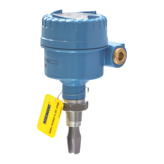
Level switch vibrating fork
Hide thumbs
Also See for Rosemount 2120:
- Reference manual (82 pages) ,
- Quick start manual (40 pages) ,
- Manual supplement (16 pages)

Related Manuals for Emerson Rosemount 2120


Summary of Contents for Emerson Rosemount 2120
- Page 1 Quick Start Guide 00825-0100-4030, Rev GB March 2022 ™ Rosemount 2120 Level Switch Vibrating Fork...
-
Page 2: Table Of Contents
Quick Start Guide March 2022 Contents About this guide...........................3 Installation........................... 5 Prepare the electrical connections....................11 Connect wiring and power up.....................26 Configuration..........................30 Operation...........................32 Rosemount 2120 Level Switch... -
Page 3: About This Guide
March 2022 Quick Start Guide About this guide This Quick Start Guide provides basic guidelines for the Rosemount 2120. Refer to the Rosemount 2120 Reference Manual for more instructions. The manual and this guide are also available electronically at Emerson.com/Rosemount. - Page 4 This is true for all systems used within the facility. CAUTION Hot surfaces The flange and process seal may be hot at high process temperatures. Allow to cool before servicing. Rosemount 2120 Level Switch...
-
Page 5: Installation
March 2022 Quick Start Guide Installation Fork alignment in a pipe installation The fork is correctly aligned by positioning the groove or notch as indicated (Figure 2-1). Figure 2-1: Correct Fork Alignment for Pipe Installation A. Tri Clamp process connections have a circular notch B. - Page 6 2. Screw the level switch into the process connection. Note Tighten using the hexagon nut only. Figure 2-3: Vertical Installation A. Gasket for BSPP (G) threaded connection Figure 2-4: Horizontal Installation A. Gasket for BSPP (G) threaded connection Rosemount 2120 Level Switch...
- Page 7 March 2022 Quick Start Guide 2.3.2 Threaded flange connection Procedure 1. Place the customer-supplied flange and gasket on the vessel (tank) nozzle. A. Gasket (customer supplied) 2. Tighten the bolts and nuts with sufficient torque for the flange and gasket. 3.
- Page 8 4. Screw the level switch into the flange thread. Note Tighten using the hexagon nut only. A. Gasket for BSPP (G) threaded connection Mounting the flanged version Procedure 1. Lower the level switch into the nozzle. A. Gasket (customer supplied) Rosemount 2120 Level Switch...
- Page 9 March 2022 Quick Start Guide 2. Tighten the bolts and nuts with sufficient torque for the flange and gasket. Mounting the Tri Clamp version Procedure 1. Lower the level switch into the flange face. A. Seal (supplied with Tri Clamp) Quick Start Guide...
- Page 10 Quick Start Guide March 2022 2. Fit the Tri Clamp. Rosemount 2120 Level Switch...
-
Page 11: Prepare The Electrical Connections
8/16 mA electronics: 24 Vdc Hazardous areas When the device is installed in hazardous areas (classified locations), local regulations and the conditions-of-use specified in applicable certificates must be observed. Review the Rosemount 2120 Product Certifications document for information. Quick Start Guide... - Page 12 Before use, check the cable glands and blanking plugs are suitably rated. • Isolate supply before connecting the switch or removing the electronics. • The Protective Earth (PE) terminal must be connected to an external earthing system. Rosemount 2120 Level Switch...
- Page 13 March 2022 Quick Start Guide 3.5.1 Direct load switching cassette Figure 3-1: Direct Load Switching (2-wire) Cassette (Red Label) – Code T Fuse 2A(T) DPST R = External load (must be fitted) N = Neutral L = Live Note A DPST (Double Pole, Single Throw) on/off switch must be fitted for safe disconnection of the power supply.
- Page 14 Mode: wet on, low level alarm < 4 mA < 4 mA 12 V 12 V DPST DPST DPST DPST LED on continuously LED flashes every LED on continuously LED flashes every second second = Load on = Load off Rosemount 2120 Level Switch...
- Page 15 March 2022 Quick Start Guide 3.5.2 PNP/PLC cassette Figure 3-2: PNP/PLC (3-wire) Cassette (Yellow Label) – Code G Wet On Mode O/P 0V F = Fuse 2A(T) Table 3-3: Electrical Parameters Parameter Value 20 - 60 Vdc < 4 mA + I <...
- Page 16 <100 μA <100 μA < 3 V < 3 V PNP dc < 3 V < 3 V <100 μA <100 μA LED on continuously LED flashes every LED on continuously LED flashes every second second Rosemount 2120 Level Switch...
- Page 17 March 2022 Quick Start Guide 3.5.3 Relay DPCO cassette (standard version) Figure 3-3: Relay DPCO Cassette, Standard Version (Green Label) – Code Fuse 0.5 (T) DPST Note A DPST (Double Pole, Single Throw) on/off switch must be fitted for safe disconnection of the power supply.
- Page 18 NC C NO NC C NO NC C NO NC C NO NC C NO NC C NO NC C NO NC C NO LED on continuously LED flashes every LED on continuously LED flashes every second second Rosemount 2120 Level Switch...
- Page 19 A DPST (Double Pole, Single Throw) on/off switch must be fitted for safe disconnection of the power supply. Fit the DPST switch as near as possible to the Rosemount 2120. Keep the DPST switch free of obstructions. Label the DPST switch to indicate it is the supply disconnection device for the Rosemount 2120.
- Page 20 NC C NO NC C NO NC C NO NC C NO NC C NO NC C NO NC C NO NC C NO LED on continuously LED flashes every LED on continuously LED flashes every second second Rosemount 2120 Level Switch...
- Page 21 Figure 3-5: NAMUR Cassette (Light Blue Label) – Code K A. A certified intrinsically safe isolating amplifier to IEC 60947-5-6 Note • This cassette is suitable for Intrinsically Safe (IS) applications and requires a certified isolating barrier. See the Rosemount 2120 Product Certifications document for Intrinsically Safe approvals. •...
- Page 22 Mode: dry on, high level alarm Mode: wet on, low level alarm > 2.2 mA < 1.0 mA > 2.2 mA < 1.0 mA LED on continuously LED flashes every LED on continuously LED flashes every second second Rosemount 2120 Level Switch...
- Page 23 Figure 3-6: 8/16 mA Cassette (Dark Blue Label) – Code H A. A certified intrinsically safe isolating amplifier to IEC 60947-5-6 Note • This cassette is suitable for Intrinsically Safe (IS) applications and requires a certified isolating barrier. See the Rosemount 2120 Product Certifications document for Intrinsically Safe approvals. •...
- Page 24 Mode: dry on, high level alarm Mode: wet on, low level alarm > 15 mA < 8.5 mA > 15 mA < 8.5 mA LED on continuously LED flashes every LED on continuously LED flashes every second second Rosemount 2120 Level Switch...
- Page 25 March 2022 Quick Start Guide Grounding Make sure grounding is done according to national and local electrical codes. Failure to do so may impair the protection provided by the equipment. 3.6.1 Signal cable shield grounding Make sure the instrument cable shield is: •...
-
Page 26: Connect Wiring And Power Up
The cover must also not to be removed in extreme environmental conditions. • Versions of the Rosemount 2120 with a metal housing are explosion-proof/flameproof. They have a cover-lock to be undone first. - Page 27 March 2022 Quick Start Guide 4. Pull cables through the cable gland/conduits. • Cassettes with a single terminal only require one cable. Identification of thread size and type: M20 x 1.5 ¾-in. ANPT M20 x 1.5 ¾-in. ANPT • Cassettes with two or more terminals may require more than one cable.
- Page 28 Quick Start Guide March 2022 7. Tighten the cable glands. Apply PTFE tape or other sealant to the threads. Metal housing: Glass-filled-nylon housing: Note Make sure to arrange the wiring with a drip loop. Rosemount 2120 Level Switch...
- Page 29 March 2022 Quick Start Guide 8. Plug and seal the unused conduit connection to avoid moisture and dust accumulation inside the housing. Apply PTFE tape or other sealant to the threads. Metal housing: Glass-filled-nylon housing: 9. Attach and tighten the cover. Make sure the cover is fully engaged.
-
Page 30: Configuration
Isolate Supply Before Removing Wet On Mode Seconds Delay A. 'Heartbeat' LED B. Rotating switch for setting output mode and time delay The recommended mode for high level alarm installations is the "Dry On" mode (Figure 5-2). Rosemount 2120 Level Switch... - Page 31 March 2022 Quick Start Guide Figure 5-2: Typical Settings for High Level Applications Dry On Wet On Seconds Delay A. Mode “Dry On” and 1 second time delay The "Wet On" mode is recommended for low level alarm installations (Figure 5-3).
-
Page 32: Operation
1 every 2 seconds Uncalibrated. 1 every 4 seconds Load fault; load current too high; load short circuit. 2 times / second Indication of successful calibration. 3 times / second Internal PCB fault. Problem (e.g. supply). Rosemount 2120 Level Switch... - Page 33 March 2022 Quick Start Guide Quick Start Guide...
- Page 34 Quick Start Guide March 2022 Rosemount 2120 Level Switch...
- Page 35 March 2022 Quick Start Guide Quick Start Guide...
- Page 36 For more information: Emerson.com © 2022 Emerson. All rights reserved. Emerson Terms and Conditions of Sale are available upon request. The Emerson logo is a trademark and service mark of Emerson Electric Co. Rosemount is a mark of one of the Emerson family of companies.