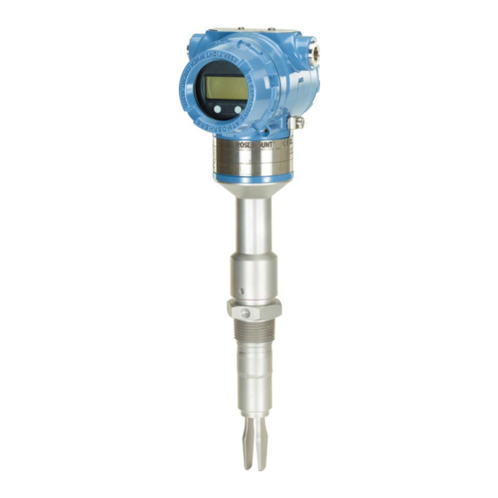
Emerson Rosemount 2140 Quick Start Manual
Level detector vibrating fork
Hide thumbs
Also See for Rosemount 2140:
- Reference manual (144 pages) ,
- Quick start manual (24 pages) ,
- Quick start manual (24 pages)
Quick Links
See also:
Reference Manual
Quick Start Guide
00825-0100-4140, Rev AA
January 2017
™
Rosemount
2140 Level Detector
Vibrating Fork
Quick Start Guide for Installation

Related Manuals for Emerson Rosemount 2140


Summary of Contents for Emerson Rosemount 2140
- Page 1 Quick Start Guide 00825-0100-4140, Rev AA January 2017 ™ Rosemount 2140 Level Detector Vibrating Fork Quick Start Guide for Installation...
- Page 2 January 2017 Quick Start Guide 1.0 About this guide This Quick Start Guide provides basic guidelines for Rosemount 2140 and 2140:SIS Vibrating Fork Liquid Level Detectors (“level detectors”). Refer to the Rosemount 2140 Reference Manual for more instructions, and the...
- Page 3 Quick Start Guide January 2017 2.0 Installation 2.1 Mounting the threaded version Step 1: Seal and protect the threads Use anti-seize paste or PTFE tape according to your site procedures. Gasket may be used as a sealant for BSPP (G) threaded connections. Step 2: Mount the level detector on tank or pipework Threaded tank or pipework connection (vertical installation) Tighten using the...
- Page 4 January 2017 Quick Start Guide Threaded flange connection 1. Place the customer supplied flange on the tank nozzle. Gasket (customer supplied) 2. Tighten the bolts and nuts with sufficient torque for the flange and gasket. 3. Screw the level detector into the flange thread. Gasket for BSPP (G) threads only...
- Page 5 Quick Start Guide January 2017 2.2 Mounting the flanged version Step 1: Lower the level detector into the nozzle Gasket (customer supplied) Step 2: Tighten the bolts and nuts...
- Page 6 January 2017 Quick Start Guide 2.3 Mounting the Tri Clamp version Step 1: Lower the level detector onto the flange face Seal (supplied with Tri Clamp) Step 2: Fit the Tri Clamp...
- Page 7 Quick Start Guide January 2017 3.0 Adjust display orientation (optional) To improve field access to wiring or get a better view of the optional LCD display: 1. Loosen the set screw until the level detector housing can rotate smoothly. a. Do not unscrew all the way. Rotating the housing, without this screw in place, can damage the internal wiring.
- Page 8 January 2017 Quick Start Guide 4.0 Prepare the electrical connections 4.1 Cable selection Use 24-14 AWG wire. Twisted-pairs and shielded wiring is recommended for environments with high EMI (electromagnetic interference). Two wires can be safely connected to each terminal screw. 4.2 Cable gland/conduit For intrinsically safe, explosion-proof/flameproof, and dust-proof installations, use the supplied blanking plug and a suitably certified cable gland/conduit entry...
- Page 9 Quick Start Guide January 2017 5.0 Connect wiring and power up Verify that the power supply is disconnected or switched off. Step 1: Remove the cover Step 2: Remove the plastic plugs Step 3: Pull the cable through the cable gland/conduit Identification of thread size and type M20 x 1.5...
- Page 10 January 2017 Quick Start Guide Step 4: Connect the cable wires Torque 7 in-lb (0.8Nm) ® Figure 2. 4-20 mA/HART Communication A. Field Communicator (IS approved for intrinsically safe installations) B. Approved IS barrier (for intrinsically safe installations only) C. HART modem D.
- Page 11 Quick Start Guide January 2017 Step 5: Ensure proper grounding Make sure grounding is done according to national and local electrical codes. Failure to do so may impair the protection provided by the equipment. Transmitter case grounding The most effective grounding method is direct connection to earth ground with minimal impedance (<...
- Page 12 January 2017 Quick Start Guide Step 6: Tighten the cable gland Apply PTFE tape or other sealant to the threads. Note Arrange the wiring with a drip loop. Step 7: Seal any unused port with the enclosed metal plug Apply PTFE tape or other sealant to the thread.
- Page 13 Quick Start Guide January 2017 Step 8: Attach and tighten the covers 1. Verify the cover jam screws are completely threaded into the housing. Cover jam screw (one per side) M2.5 2. Attach and tighten the covers. Make sure the covers are fully engaged. 3.
- Page 14 2. In the Message field, enter “HART5” or “HART7” and then 27 trailing spaces. 7.0 Configure level detector using Guided Setup The Rosemount 2140 and Rosemount 214:SIS can be configured using a Field Communicator, a PC running the AMS™ Suite: Intelligent Device Manager, or any other Device Descriptor (DD) compatible host system.
- Page 15 Quick Start Guide January 2017...
- Page 16 Middle East and Africa Regional Office Standard Terms and Conditions of Sale can be found at www.Emerson.com/en-us/Terms-of-Use Emerson Automation Solutions The Emerson logo is a trademark and service mark of Emerson Emerson FZE P.O. Box 17033, Electric Co. Jebel Ali Free Zone - South 2...