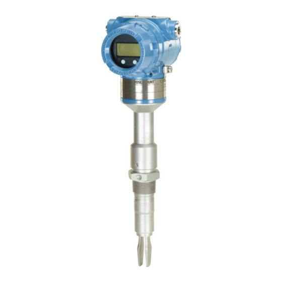
Emerson Rosemount 2140 Quick Start Manual
Level detectors. vibrating fork
Hide thumbs
Also See for Rosemount 2140:
- Reference manual (144 pages) ,
- Quick start manual (24 pages) ,
- Reference manual (112 pages)

Related Manuals for Emerson Rosemount 2140


Summary of Contents for Emerson Rosemount 2140
- Page 1 Quick Start Guide 00825-0100-4140, Rev AD July 2021 ™ Rosemount 2140 and 2140:SIS Level Detectors Vibrating Fork...
-
Page 2: Table Of Contents
Quick Start Guide July 2021 Contents About this guide...........................3 Installation........................... 5 Prepare the electrical connections....................12 Connect wiring and power-up....................15 Configuration..........................20 Rosemount 2140 and 2140:SIS Level Detectors... -
Page 3: About This Guide
July 2021 Quick Start Guide About this guide This Quick Start Guide provides basic guidelines for the Rosemount 2140 and 2140:SIS Level Detectors. Refer to the Rosemount 2140 and 2140:SIS Reference Manual for more instructions. The manual and this guide are also available electronically at Emerson.com/Rosemount. - Page 4 This is true for all systems used within the facility. CAUTION Hot surfaces The flange and process seal may be hot at high process temperatures. Allow to cool before servicing. Rosemount 2140 and 2140:SIS Level Detectors...
-
Page 5: Installation
July 2021 Quick Start Guide Installation Fork alignment in a pipe installation The fork is correctly aligned by positioning the groove or notch as indicated (Figure 2-1). Figure 2-1: Correct Fork Alignment for Pipe Installation A. Tri Clamp process connections have a circular notch B. - Page 6 2. Screw the level detector into the process connection. Note Tighten using the hexagon nut only. Figure 2-3: Vertical Installation A. Gasket for BSPP (G) threaded connection Figure 2-4: Horizontal Installation A. Gasket for BSPP (G) threaded connection Rosemount 2140 and 2140:SIS Level Detectors...
- Page 7 July 2021 Quick Start Guide 2.3.2 Threaded flange connection Procedure 1. Place the customer-supplied flange and gasket on the vessel (tank) nozzle. A. Gasket (customer supplied) 2. Tighten the bolts and nuts with sufficient torque for the flange and gasket. 3.
- Page 8 Quick Start Guide July 2021 4. Screw the level detector into the flange thread. Note Tighten using the hexagon nut only. A. Gasket for BSPP (G) threaded connection Rosemount 2140 and 2140:SIS Level Detectors...
- Page 9 July 2021 Quick Start Guide Mounting the flanged version Procedure 1. Lower the level detector into the nozzle. A. Gasket (customer supplied) 2. Tighten the bolts and nuts with sufficient torque for the flange and gasket. Quick Start Guide...
- Page 10 Quick Start Guide July 2021 Mounting the Tri Clamp version Procedure 1. Lower the level detector into the flange face. A. Seal (supplied with Tri Clamp) 2. Fit the Tri Clamp. Rosemount 2140 and 2140:SIS Level Detectors...
- Page 11 July 2021 Quick Start Guide Adjust display orientation (optional) To improve field access to wiring or to better view the optional LCD display: Procedure 1. Loosen the set screw until the level detector housing can rotate smoothly. Do not unscrew all the way. Rotating the housing, without this screw in place, can damage the internal wiring.
-
Page 12: Prepare The Electrical Connections
Maximum of 1 W, and current maximum is 23 mA. Hazardous areas When the device is installed in hazardous areas (classified locations), local regulations and the conditions-of-use specified in applicable certificates must be observed. Review the Rosemount 2140 Product Certifications document for information. - Page 13 July 2021 Quick Start Guide Figure 3-1: Load Limitations 1400 1392 1200 1000 10.5 16.3 42.4 Maximum loop resistance = 43.5 × (external power supply voltage - 10.5) A. Loop resistance in Ohms (Ω) B. External power supply voltage (Vdc) Wiring diagram ®...
- Page 14 Connected to a good earth ground at the power supply end. Figure 3-4: Signal Cable Shield Grounding at Power Supply End A. Trim shield and insulate B. Minimize distance C. Trim shield D. Connect shield back to the power supply ground Rosemount 2140 and 2140:SIS Level Detectors...
-
Page 15: Connect Wiring And Power-Up
July 2021 Quick Start Guide Connect wiring and power-up Procedure Verify the power supply is disconnected. 2. Remove the field terminals cover. In an explosion-proof/flameproof installation, do not remove the level detector covers when power is applied to the unit. Covers are also not to be removed in extreme environmental conditions. - Page 16 3. Remove the plastic plugs. 4. Pull the cable through the cable gland/conduit. Identification of thread size and type: ½-14 NPT M20 x 1.5 5. Connect the cable wires. Torque 7 in-lb (0.8 Nm) 6. Ensure proper grounding. Rosemount 2140 and 2140:SIS Level Detectors...
- Page 17 July 2021 Quick Start Guide 7. Tighten the cable gland. Apply PTFE tape or other sealant to the threads. Note Make sure to arrange the wiring with a drip loop. 8. Plug and seal the unused conduit connection to avoid moisture and dust accumulation inside the housing.
- Page 18 Verify the cover jam screw is completely threaded into the housing. M2.5 b) Attach and tighten the cover. Make sure the cover is fully engaged. There should be no gap between the cover and the housing. Rosemount 2140 and 2140:SIS Level Detectors...
- Page 19 July 2021 Quick Start Guide Required for explosion-proof/flameproof installations only: a) Turn the cover jam screw counterclockwise until it contacts the cover. M2.5 b) Turn the jam screw an extra ½ turn counterclockwise to secure the cover. c) Verify that the cover cannot be removed. 11.
-
Page 20: Configuration
AMS Device Manager versions 10.5 or later are compatible with HART Revision 7. Procedure 1. Click on Manual Setup, and then select the HART tab. 2. Select Change HART Revision and then follow the on screen prompts. Rosemount 2140 and 2140:SIS Level Detectors... - Page 21 July 2021 Quick Start Guide Switching HART revision using a handheld communicator To switch the HART revision mode from DD-based handheld communicator: Procedure 1. From the Home screen, select Configure. 2. Select Manual Setup → HART → Communication Settings → Change HART Revision.
- Page 22 1. Turn on the handheld communicator and connect to the device. 2. Select Configure → Guided Setup. 3. Select Basic Setup and follow the on-screen instructions. 5.2.3 Configure using the LOI The Guided Setup wizard is not available on the LOI (Local Operator Interface). Rosemount 2140 and 2140:SIS Level Detectors...
- Page 23 July 2021 Quick Start Guide Quick Start Guide...
- Page 24 For more information: www.emerson.com © 2021 Emerson. All rights reserved. Emerson Terms and Conditions of Sale are available upon request. The Emerson logo is a trademark and service mark of Emerson Electric Co. Rosemount is a mark of one of the Emerson family of companies.