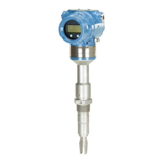
Emerson Rosemount 2140 Quick Start Manual
Level detectors vibrating fork
Hide thumbs
Also See for Rosemount 2140:
- Reference manual (144 pages) ,
- Quick start manual (24 pages) ,
- Reference manual (112 pages)

Related Manuals for Emerson Rosemount 2140


Summary of Contents for Emerson Rosemount 2140
- Page 1 Quick Start Guide 00825-0100-4140, Rev AC August 2020 ™ Rosemount 2140 and 2140:SIS Level Detectors Vibrating Fork...
-
Page 2: Table Of Contents
Quick Start Guide August 2020 Contents About this guide...........................3 Installation........................... 5 Prepare the electrical connections....................11 Connect wiring and power-up....................14 Configuration..........................19 Rosemount 2140 and 2140:SIS Level Detectors... -
Page 3: About This Guide
About this guide ™ This Quick Start Guide provides basic guidelines for the Rosemount 2140 and 2140:SIS Level Detectors. Refer to the Rosemount 2140 and 2140:SIS Reference Manual for more instructions. The manual and this guide are also available electronically at Emerson.com/Rosemount. - Page 4 This is true for all systems used within the facility. CAUTION Hot surfaces The flange and process seal may be hot at high process temperatures. Allow to cool before servicing. Rosemount 2140 and 2140:SIS Level Detectors...
-
Page 5: Installation
August 2020 Quick Start Guide Installation Fork alignment in a pipe installation Figure 2-1: Correct Fork Alignment for Pipe Installation A. Tri Clamp process connections have a circular notch B. Threaded process connections have a groove Fork alignment in a vessel (tank) installation Figure 2-2: Correct Fork Alignment for Vessel (Tank) Installation A. - Page 6 A gasket may be used as a sealant for BSPP (G) threaded connections. 2.3.2 Threaded vessel (tank) or pipework connection • Vertical installation. • Horizontal installation. A. Tighten using the hexagon nut only B. Gasket for BSPP (G) threaded connection Rosemount 2140 and 2140:SIS Level Detectors...
- Page 7 August 2020 Quick Start Guide 2.3.3 Threaded flange connection Procedure 1. Place the customer-supplied flange and gasket on the vessel (tank) nozzle. A. Gasket (customer supplied) 2. Tighten the bolts and nuts with sufficient torque for the flange and gasket. 3.
- Page 8 Quick Start Guide August 2020 Mounting the flanged version Procedure 1. Lower the level detector into the nozzle. A. Gasket (customer supplied) 2. Tighten the bolts and nuts with sufficient torque for the flange and gasket. Rosemount 2140 and 2140:SIS Level Detectors...
- Page 9 August 2020 Quick Start Guide Mounting the Tri Clamp version Procedure 1. Lower the level detector into the flange face. A. Seal (supplied with Tri Clamp) 2. Fit the Tri Clamp. Quick Start Guide...
- Page 10 If the desired location cannot be achieved due to thread limit, rotate the housing counterclockwise. 3. Re-tighten the set screw. Figure 2-3: Housing Rotation Do not attempt to rotate the display beyond the thread limits in. torque 30 in-lb (3 Nm) Rosemount 2140 and 2140:SIS Level Detectors...
-
Page 11: Prepare The Electrical Connections
Maximum of 1 W, and current maximum is 23 mA. Hazardous areas When the level detector is installed in hazardous areas (classified locations), local regulations and the conditions-of-use specified in applicable certificates must be observed. Review the Rosemount 2140 Product Certifications document for information. - Page 12 Wiring diagram ® Figure 3-2: 4-20 mA/HART Communication A. Handheld communicator B. Approved IS barrier (for Intrinsically Safe installations only) C. HART modem D. Load resistance (≥250 Ω) E. Current meter F. Power supply Rosemount 2140 and 2140:SIS Level Detectors...
- Page 13 August 2020 Quick Start Guide Grounding Always ground the housing in accordance with national and local laws. 3.8.1 Grounding using the cable shield Make sure the instrument cable shield is: • Trimmed close and insulated from touching the level detector housing. •...
-
Page 14: Connect Wiring And Power-Up
Turn the jam screw clockwise until it is completely threaded into the housing. M2.5 b) Turn the cover counter-clockwise until it is removed from the housing. c) Keep the cover O-ring safe. Replace the O-ring if it is worn or damaged. Rosemount 2140 and 2140:SIS Level Detectors... - Page 15 August 2020 Quick Start Guide 3. Remove the plastic plugs. 4. Pull the cable through the cable gland/conduit. ½-14 NPT M20 x 1.5 (No marking) 5. Connect the cable wires (see Wiring diagram). Torque 7 in-lb (0.8 Nm) 6. Ensure proper grounding (see Grounding). Quick Start Guide...
- Page 16 Make sure to arrange the wiring with a drip loop. 8. Plug and seal the unused conduit connection to avoid moisture and dust accumulation inside the housing. Apply PTFE tape or other sealant to the threads. Rosemount 2140 and 2140:SIS Level Detectors...
- Page 17 August 2020 Quick Start Guide 9. Attach and tighten the covers. Make sure the covers are fully engaged. a) Verify the cover jam screws are completely threaded into the housing. M2.5 b) Attach and tighten the covers. Make sure the covers are fully engaged.
- Page 18 Quick Start Guide August 2020 M2.5 11. Connect the power supply. Rosemount 2140 and 2140:SIS Level Detectors...
-
Page 19: Configuration
Confirm correct device driver • Verify that the correct Device Driver (DD) or Device Type Manager (DTM) is loaded on your systems to ensure proper communication. • Download the latest DD/DTM at Emerson.com/DeviceInstallKits. ® 5.1.2 Confirm HART revision capability If using HART-based control or asset management systems, confirm the HART capability of those systems prior to installation of the level detector . - Page 20 2. Select View → Device Connection View. 3. In the Device Connection View, double-click the HART modem icon. 4. Double-click the device icon. 5. Select Configure → Guided Setup. 6. Select Basic Setup and follow the on-screen instructions. Rosemount 2140 and 2140:SIS Level Detectors...
- Page 21 August 2020 Quick Start Guide 5.2.2 Configure using Field Communicator Procedure 1. Turn on the Field Communicator and connect to the device. 2. Select Configure → Guided Setup. 3. Select Basic Setup and follow the on-screen instructions. 5.2.3 Configure using the LOI The Guided Setup wizard is not available on the LOI (Local Operator Interface).
- Page 22 Quick Start Guide August 2020 Rosemount 2140 and 2140:SIS Level Detectors...
- Page 23 August 2020 Quick Start Guide Quick Start Guide...
- Page 24 The Emerson logo is a Twitter.com/Rosemount_News trademark and service mark of Emerson Electric Facebook.com/Rosemount Co. Rosemount is a mark of one of the Emerson Youtube.com/user/ family of companies. All other marks are the RosemountMeasurement property of their respective owners.