Table of Contents
Model No. HETL13913.0
Serial No.
Write the serial number in the space
above for reference.
Serial Number
Decal
CUSTOMER SERVICE
UNITED KINGDOM
Call: 08457 089 009
From Ireland: 053 92 36102
Website: www.iconsupport.eu
E-mail: [email protected]
Write:
ICON Health & Fitness, Ltd.
c/o HI Group PLC
Express Way
CASTLEFORD
WF10 5QJ
UNITED KINGDOM
AUSTRALIA
Call: 1800 993 770
E-mail: [email protected]
Write:
ICON Health & Fitness
PO Box 635
WINSTON HILLS NSW 2153
AUSTRALIA
CAUTION
Read all precautions and instruc-
tions in this manual before using
this equipment. Save this manual
for future reference.
USER'S MANUAL
www.iconeurope.com
Table of Contents

Related Manuals for Healthrider H150t Treadmill


Summary of Contents for Healthrider H150t Treadmill
- Page 1 Model No. HETL13913.0 Serial No. USER’S MANUAL Write the serial number in the space above for reference. Serial Number Decal CUSTOMER SERVICE UNITED KINGDOM Call: 08457 089 009 From Ireland: 053 92 36102 Website: www.iconsupport.eu E-mail: [email protected] Write: ICON Health & Fitness, Ltd. c/o HI Group PLC Express Way CASTLEFORD...
-
Page 2: Table Of Contents
Apply the decal in the location shown. Note: The decals may not be shown at actual size. 305284 HEALTHRIDER is a registered trademark of ICON IP, Inc. -
Page 3: Important Precautions
IMPORTANT PRECAUTIONS WARNING: To reduce the risk of burns, fire, electric shock, or injury to persons, read all important precautions and instructions in this manual and all warnings on your treadmill before using your treadmill. ICON assumes no responsibility for personal injury or property damage sus- tained by or through the use of this product. - Page 4 DANGER: 21. Do not attempt to raise, lower, or move the Always unplug the power treadmill until it is properly assembled. (See cord immediately after use, before clean- ASSEMBLY on page 7, and HOW TO FOLD ing the treadmill, and before performing the AND MOVE THE TREADMILL on page 25.) maintenance and adjustment procedures You must be able to safely lift 45 lbs.
-
Page 5: Before You Begin
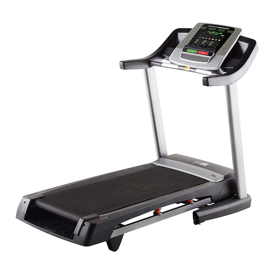
Thank you for selecting the new HEALTHRIDER manual. To help us assist you, note the product model ® H150T treadmill. The H150T treadmill provides an number and serial number before contacting us. The impressive selection of features designed to make your model number and the location of the serial number workouts at home more effective and enjoyable. -
Page 6: Part Identification Chart
PART IDENTIFICATION CHART Use the drawings below to identify small parts used for assembly. The number in parentheses below each draw- ing is the key number of the part, from the PART LIST near the end of this manual. The number following the key number is the quantity used for assembly. -
Page 7: Assembly
ASSEMBLY • Assembly requires two persons. • To identify small parts, see page 6. • Place all parts in a cleared area and remove the • Assembly requires the following tools: packing materials. Do not dispose of the packing the included hex keys materials until you finish all assembly steps. - Page 8 2. Make sure that the power cord is unplugged. Hole With the help of a second person, tip the tread- mill onto its right side. Pull the Upright Wire (91) and the base ground wire (A) through the indicated hole in the Base (29).
- Page 9 4. Identify the Left Upright (84). Have a second person hold the Left Upright near the Base (29). See the inset drawing. Tie the wire tie in the Left Upright (84) securely around the end of the Upright Wire (91). Then, pull the other end of the wire tie until the Upright Wire is routed through Wire the Left Upright.
- Page 10 6. Identify the Left and Right Base Covers (88, 89). Slide the Left Base Cover (88) onto the Left Upright (84). Slide the Right Base Cover (89) onto the Right Upright (85). Do not press the Base Covers into place yet. 7.
- Page 11 8. Attach the right Handrail (79) to the Right Upright (85) with two 5/16" x 2 3/4" Screws (12) and two 5/16" Star Washers (8). Do not tighten the Screws yet. Remove the two indicated screws (C) from the right Handrail (79) and discard them. 9.
- Page 12 10. Identify the Left and Right Trays (95, 96). Attach the Left and Right Trays (95, 96) to the Console Base (98) with eight #8 x 1/2" Screws (1). Tip: It may be easier to start the two inside Screws and then slide the Trays into place before tightening the other six Screws.
- Page 13 12. With the help of a second person, hold the con- Console sole assembly near the Handrails (79) (only one Assembly Handrail is shown). Connect the ground wire from the console assembly to the Ground Wire (80) on the Pulse Crossbar (81).
- Page 14 14. Attach the Pulse Crossbar (81) to the console assembly with six #8 x 1/2" Screws (1). Start all Console six Screws, and then tighten them. Assembly Firmly tighten the four 5/16" x 5/8" Screws (11). 15. Firmly tighten the four 3/8" x 2 3/4" Screws (22), and then tighten the four 3/8"...
- Page 15 16. Raise the Frame (57) to the position shown. Have a second person hold the Frame until step 17 is completed. Orient the Storage Latch (54) so that the large barrel and the latch knob are oriented as shown. Remove any ties from the end of the Storage Latch (54).
-
Page 16: The Chest Heart Rate Monitor
THE CHEST HEART RATE MONITOR HOW TO PUT ON THE HEART RATE MONITOR • Do not expose the heart rate monitor to direct sun- light for extended periods of time; do not expose it to The heart rate temperatures above 122° F (50° C) or below 14° F monitor consists of (-10°... -
Page 17: Operation And Adjustment
OPERATION AND ADJUSTMENT HOW TO PLUG IN THE POWER CORD Follow the steps below to plug in the power cord. This product must be earthed. If it should malfunc- 1. Plug the indicated end of the power cord into the tion or break down, earthing provides a path of least socket on the treadmill. - Page 18 CONSOLE DIAGRAM FEATURES OF THE CONSOLE You can even listen to your favorite workout music or audio books with the console’s sound system while you The treadmill console offers an impressive array of exercise. features designed to make your workouts more effec- To turn on the power, see page 19.
- Page 19 HOW TO TURN ON THE POWER HOW TO USE THE MANUAL MODE IMPORTANT: If the treadmill has been exposed to 1. Insert the key into the console. cold temperatures, allow it to warm to room tem- perature before you turn on the power. If you do See HOW TO TURN ON THE POWER at the left.
- Page 20 5. Follow your progress with the displays. 6. Measure your heart rate if desired. The matrix—When Note: If you use the handgrip heart rate moni- tor and the chest heart rate monitor at the same you select the manual time, the console will not display your heart mode, the matrix will display a track that rate accurately.
- Page 21 HOW TO USE AN ONBOARD WORKOUT The workout will continue in this way until the last segment of the profile flashes in the display and the 1. Insert the key into the console. last segment ends. The walking belt will then slow to a stop.
- Page 22 HOW TO USE AN IFIT WORKOUT When you select an iFit workout, the display will show the duration of the workout, the distance you Note: To use an iFit workout, you must have access to will walk or run, the approximate number of calories a computer with a USB port and an internet connec- you will burn, the name of the workout, and the tion.
- Page 23 HOW TO USE A SET-A-GOAL WORKOUT 5. Measure your heart rate if desired. 1. Insert the key into the console. See step 6 on page 20. 6. Turn on the fan if desired. See HOW TO TURN ON THE POWER on page 19. 2.
- Page 24 THE INFORMATION MODE displays will remain lit, although the buttons will not function. If the demo mode is turned on, the word The console features an information mode that keeps ON will appear in the center display. To turn on or track of treadmill information and allows you to person- turn off the demo mode, press the Enter button.
-
Page 25: How To Fold And Move The Treadmill
HOW TO FOLD AND MOVE THE TREADMILL HOW TO FOLD THE TREADMILL HOW TO MOVE THE TREADMILL To avoid damaging the treadmill, adjust the incline Before moving the treadmill, fold it as described at the to zero before you fold the treadmill. Then, remove left. -
Page 26: Troubleshooting
TROUBLESHOOTING Most treadmill problems can be solved by follow- c. Remove the key from the console, and then ing the simple steps below. Find the symptom that reinsert it. applies, and follow the steps listed. If further assis- tance is needed, see the front cover of this manual. d. - Page 27 SYMPTOM: The walking belt slows when walked on Locate the Reed Switch (52) and the Magnet (51) on the left side of the Pulley (50). Turn the Pulley until the Magnet is aligned with the Reed Switch. a. If an extension cord is needed, use only a 3-con- Make sure that the gap between the Magnet and ductor, 14-gauge (1 mm ) cord that is no longer...
- Page 28 SYMPTOM: The walking belt is not centered SYMPTOM: The walking belt slips when walked on between the foot rails a. First, remove the key and UNPLUG THE POWER IMPORTANT: If the walking belt rubs against the CORD. Using the hex key, turn both idler roller foot rails, the walking belt may become damaged.
-
Page 29: Exercise Guidelines
EXERCISE GUIDELINES Burning Fat—To burn fat effectively, you must exer- WARNING: cise at a low intensity level for a sustained period of Before beginning this time. During the first few minutes of exercise, your or any exercise program, consult your physi- body uses carbohydrate calories for energy. -
Page 30: Part List
PART LIST Model No. HETL13913.0 R0613A Key No. Qty. Description Key No. Qty. Description #8 x 1/2" Screw Magnet 3/8" x 2" Bolt Reed Switch 3/8" x 1 1/4" Screw Cable Tie #10 x 3/4" Screw Storage Latch #10 Star Washer Drive Motor #8 x 1/2"... - Page 31 Key No. Qty. Description Key No. Qty. Description Console Frame Frame Endcap Motor Bushing Frame Endcap Cover #8 Ground Bolt Left Wheel Cap #8 Nut Receptacle Filter Bracket Grounding Bracket Filter 1/2" Nut Motor Isolator – User’s Manual Note: Specifications are subject to change without notice. For information about ordering replacement parts, see the back cover of this manual.
-
Page 32: Exploded Drawing
EXPLODED DRAWING A Model No. HETL13913.0 R0613A... - Page 33 EXPLODED DRAWING B Model No. HETL13913.0 R0613A...
- Page 34 EXPLODED DRAWING C Model No. HETL13913.0 R0613A...
- Page 35 EXPLODED DRAWING D Model No. HETL13913.0 R0613A...
-
Page 36: Ordering Replacement Parts
ORDERING REPLACEMENT PARTS To order replacement parts, please see the front cover of this manual. To help us assist you, be prepared to provide the following information when contacting us: • the model number and serial number of the product (see the front cover of this manual) • the name of the product (see the front cover of this manual) • the key number and description of the replacement part(s) (see the PART LIST and the EXPLODED DRAWING near the end of this manual)