OASE BioMaster 250/350/600/850, BioMaster Thermo 250/350/600/850 Manual
- Operating instructions manual (205 pages) ,
- Operating instructions manual (20 pages) ,
- Operating instructions manual (34 pages)
- 1 Warnings used in these instructions
- 2 Cross-references used in these instructions
- 3 PRODUCT DESCRIPTION
- 4 ACCESSING THE UNIT
- 5 INSTALLATION AND CONNECTION
- 6 COMMISSIONING/START-UP
- 7 TROUBLESHOOTING
- 8 MAINTENANCE AND CLEANING
- 9 WEAR PARTS
- 10 SPARE PARTS
- 11 TECHNICAL DATA
- 12 SYMBOLS ON THE UNIT
- 13 IMPORTANT SAFETY INSTRUCTIONS
- 14 Documents / Resources
Warnings used in these instructions
 NOTE
NOTE
Indicates information intended to give the user a better understanding.

Cross-references used in these instructions
 A Reference to a figure, e.g. Fig. A.
 Reference to another section.
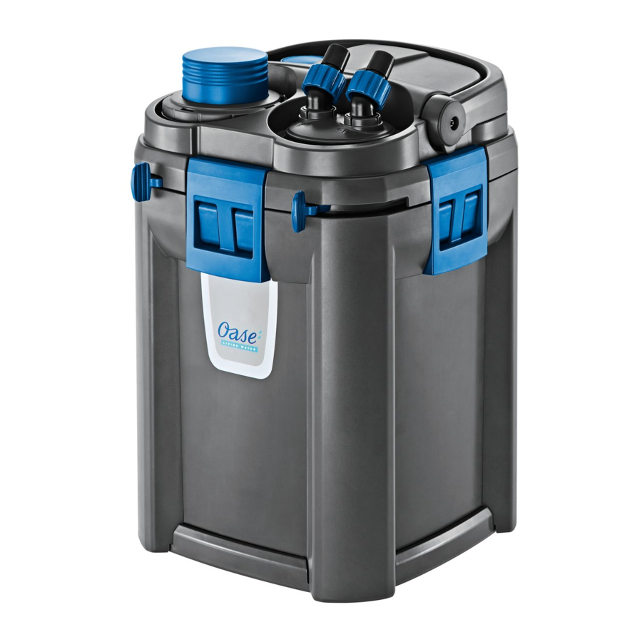
PRODUCT DESCRIPTION
Intended use
BioMaster 250/350/600/850, BioMaster Thermo 250/350/600/850, referred to in the following as "unit", may only be used as specified in the following:
- BioMaster 250/350/600/850: Water filtering and recirculation
- BioMaster Thermo 250/350/600/850: Water heating, filtering and recirculation
- For operation with freshwater or saltwater
- Operation under observance of the technical data
The following restrictions apply to the unit:
- Only use indoors and for aquaristic purposes in the home (not for commercial use)
- Only operate with water at a water temperature of +39°F to +95°F
Function description
Drawn in by a pump in the unit head, the water first flows through the pre-filter then from the bottom to the top through sealed filtration pathways to ensure water flows through all the superimposed layers of filter media. The water then flows back into the aquarium via the spray bar or water distributor. Filter foams with varying pore densities, and Hel-X Biomedia serve as filter media.
In units with heater, the water is heated during its passage through the filter system.
Filter media in Scope of delivery
| BioMaster/ BioMaster Thermo 250 | BioMaster/ BioMaster Thermo 350 | BioMaster/ BioMaster Thermo 600 | BioMaster/ BioMaster Thermo 850 | |
| 45 ppi Carbon Pre-filter foam | 4 | 5 | 6 | 6 |
| 30 ppi Coarse filter foam | 1 | 1 | 1 | 1 |
| 20 ppi Ultra-coarse filter foam | 2 | 3 | 3 | 4 |
| Hel-X Biomedia | 1 unit | 1 unit | 2 units | 2 units |
Hel-X Biomedia has an extremely large protected settlement surface (8610 ft²/265 gallons) that allows beneficial bacteria to grow and thrive. The material is designed to stop floating as soon as it reaches a certain level of bacteria colonization. Hel-X Biomedia should always be contained in the provided mesh bag.
Scope of delivery
  A A | ||
| BioMaster Thermo | QTY | |
| 1 | BioMaster Thermo 250: HeatUp 150 Heater BioMaster Thermo 350: HeatUp 200 Heater BioMaster Thermo 600: HeatUp 300 Heater BioMaster Thermo 850: HeatUp 400 Heater | 1 |
| 2 | Instruction manual HeatUp | 1 |
| BioMaster, BioMaster Thermo | QTY | |
| 3 | Instruction manual BioMaster 250/350/600/850, BioMaster Thermo 250/350/600/850 | 1 |
| 4 | HeatUp adapter | 1 |
| 5 | Plug | 1 |
| 6 | Handle | 1 |
| 7 | Unit head | 1 |
| 8 | Pre-filter with Prime button | 1 |
| 9 | Inlet and outlet connection unit with check valve | 1 |
| 10 | Fastener clamps | 4 |
| 11 | Filter unit, filled with filter media | 1 |
| 12 | Rubber feet | 4 |
  B B | ||
| Inlet assembly, Outlet assembly | QTY | |
| 1 | Inlet pipe | 1 |
| 2 | Flexible tubing (5/8 in. ID x 13 ft.) | 1 |
| 3 | Spray bar | 2 |
| 4 | Suction cup | 5 |
| 5 | Adjustable inlet/outlet adapter | 2 |
| 6 | Inlet pipe adapter | 1 |
| 7 | Inlet strainer | 1 |
| 8 | Clip | 5 |
| 9 | Elbow | 1 |
| 10 | Locking nut | 4 |
| 11 | Connecting piece | 1 |
| 12 | Water distributor nozzle | 1 |
| 13 | Spray bar cap | 1 |
ACCESSING THE UNIT
NOTE
The following applies to all units with a heater:
- Adhere to the rules for careful handling. (
![]() Careful handling of the heater)
Careful handling of the heater)
Careful handling of the heater

Hot surface!
Risk of burns when touching the glass bulb.
Risk of breaking the glass!
The glass bulb of the heater can break and cause cuts.
Removing the heater
(BioMaster Thermo models)
The heater has to be removed for cleaning, maintenance, and for removing the unit head.
How to proceed:
![]() C
C

- Lift up the handle.
- Twist the adapter counter-clockwise and pull up. Do not remove the heater from the HeatUp adapter.
Fitting the heater
How to proceed:
![]() D
D

- Twist the HeatUp adapter, assembled with the heater, clockwise into the threaded hole.
- Place the heater's power connection cable into the cable guide.
- Put the handle down.
- For retrofitting HeatUp heater in non thermo models
![]() Retrofitting the heater
Retrofitting the heater
Removing the inlet and outlet connection unit
The connection unit has to be removed for cleaning, maintenance, and for removing the unit head when tubing is connected.
Prerequisite: The lever can only be moved when the pre-filter is locked.
How to proceed:
![]() E
E

- Move the lever to the "UNLOCK" position.
- The inlet and outlet are closed.
- Remove the connection unit. Set it to the side with the tubing still connected.
Fitting the inlet and outlet connection unit
Prerequisite: The lever can only be moved when the pre-filter is locked.
How to proceed:
![]() F
F

- Fit the connection unit and push it into the unit head as far as it goes.
- Ensure that the ridges on the connection unit are correctly aligned to the recesses on the unit head.
- Move the lever to the "LOCK" position.
- The inlet and outlet are open.
Removing the pre-filter
The pre-filter has to be removed for cleaning, maintenance, and for removing the unit head.
Prerequisite: The lever can only be moved when the connection unit is unlocked.
How to proceed:
![]() G
G

- Move the lever to the "UNLOCK" position. The inlet and outlet are already closed.
- Pull out the pre-filter.
Fitting the pre-filter
Prerequisite: The lever can only be moved when the connection unit is unlocked.
How to proceed:
![]() H
H

- Fit the pre-filter into the opening and firmly push it into the unit head as far as it goes.
- Ensure that the ridges on the pre-filter are correctly aligned to the recesses on the unit head.
- Move the lever to the "LOCK" position.
- The pre-filter is locked.
Dismantling the unit head
The unit head has to be removed for cleaning, maintenance, and for changing the filter media.
Prerequisites:
- The heater has been removed. (
![]() Removing the heater)
Removing the heater) - The connection unit has been removed. (
![]() Removing the connection unit)
Removing the connection unit) - The pre-filter has been removed. (
![]() Removing the pre-filter)
Removing the pre-filter)
How to proceed:
![]() I
I

- Lift up the handle.
- Undo the fastener clamps by pulling the bottom of the clamp out and then pushing the clamp up.
- Remove the unit head.
Fitting the unit head
How to proceed:
![]() J
J

- Check that the seal on the unit head is correctly positioned.
- Ensure that the filter baskets are correctly assembled and aligned. (
![]() Cleaning/replacing the filter media)
Cleaning/replacing the filter media) - Fit the unit head onto the filter unit.
- Ensure that the opening for the pre-filter is aligned to the recess in the filter baskets.
- Lock the fastener clamps in place.
- Put the handle down.
- Refit the heater. (
![]() Fitting the heater)
Fitting the heater) - Refit the pre-filter. (
![]() Fitting the pre-filter)
Fitting the pre-filter) - Refit the connection unit (
![]() Fitting the inlet and outlet connection unit)
Fitting the inlet and outlet connection unit)
INSTALLATION AND CONNECTION
Order of tasks to be carried out:
- Fit the rubber feet (
![]() Fitting the rubber feet)
Fitting the rubber feet) - Prepare the filter media (
![]() Cleaning/replacing the filter media)
Cleaning/replacing the filter media) - As an option: OASE HeatUp Retrofitting (heater) (
![]() Retrofitting the heater)
Retrofitting the heater) - Install the unit
- Install the unit next to or under the aquarium. Note the maximum head height. (
![]() Technical data)
Technical data)
- Install the unit next to or under the aquarium. Note the maximum head height. (
- Establish the connections (
![]() Establishing the connections)
Establishing the connections)
Fitting the rubber feet
How to proceed:
![]() K
K

Prepare the filter media
NOTE
Thoroughly rinse out all filter material with warm tap water before using for the first time in order to remove any soiling. ( Cleaning/replacing the filter media)
Retrofitting the heater
BioMaster 250/350/600/850 non Thermo models can be retrofitted with OASE HeatUp heater.
| BioMaster | 250 | 350 | 600 | 850 | |
| HeatUp | 25 | - | - | - | - |
| 50 |  | | | | |
| 100 | | | | | |
| 150 |  | | | | |
| 200 | - | | | | |
| 300 | - | - | | | |
| 400 | - | - | - | | |
: Suitable
: Particularly recommended
Prerequisite: The filter unit is unplugged. ( Switching off the unit)
NOTE
When the filter is filled with water, water may spill when the heater is inserted.
How to proceed:
![]() L
L

- Twist the plug counter-clockwise and remove.
- Moisten the heater with water and gently push the heater into the HeatUp adapter as far as it goes.
- Fit the heater into the filter unit. (
![]() Fitting the device)
Fitting the device)
Establishing the connections
Assembling the inlet assembly
How to proceed:
![]() M
M

- Assemble the inlet assembly.
Assembling the outlet assembly
The outlet assembly can either be installed using the spray bars or the water distributor
How to proceed:
![]() N
N

- Assembling the outlet assembly using spray bars
- Connect the two spray bars via the connecting piece.
- Seal spray bar assembly with cover cap.
- Attach spray bars to adjustable outlet adapter via elbow.
- Screw locking nut onto adjustable outlet adapter.
- Connect the clips to the suction cups. These will be used to attach the outlet assembly to the tank.
- Attach the clips at the spray bars and adjustable outlet adapter as shown.
- Use a coin or a flat head screwdriver to turn the flow regulator on the outlet adapter to MAX.
- Assembling the outlet assembly using the water distributor nozzle
- Attach the water distributor nozzle to adjustable outlet adapter via elbow.
- Screw locking nut onto adjustable outlet adapter.
- Connect the clip to the suction cup. This will be used to attach the intake assembly to the tank.
- Attach the clips at the adjustable outlet adapter as shown.
- Use a coin or a flat head screwdriver to turn the flow regulator on the outlet adapter to MAX.
Connecting the tubing
The procedure is identical for the inlet (IN) and outlet (OUT).
Prerequisite: Install the unit. Install the unit next to or under the aquarium. Note the maximum head height. ( Technical data)
How to proceed:
![]() O
O

- Fasten the inlet assembly and outlet assembly in the aquarium using suction cups.
- Shorten the tubing to the required length.
- Choose the length so that the tubing cannot kink in the intended installation position.
- Screw the locking nut onto the inlet and outlet connection unit on the unit head.
- Push the tubing onto the connection unit and turn the locking nut counter-clockwise to fix the tubing in place.
- Push the other end of the tubing onto the inlet/outlet adapter of the inlet assembly/outlet assembly and turn the tubing locking nut counter-clockwise to fix the tubing in place.
COMMISSIONING/START-UP
For initial start-up or after thorough cleaning, it is necessary to expel air from the filter system. When the filter unit, inlet assembly and tubing are free of trapped air, the pump can convey the water by itself through the filter system. ( Expelling air from the filter system)
Expelling air from the filter system
Prerequisite: The unit is unplugged. ( Switching off the unit)
How to proceed:
![]() P
P

- Press the priming button and release it until the water flows out of the tank into the filter.
Switching on the unit
NOTE
Ensure that the pump never runs dry! The pump will be destroyed.
NOTE
 Risk of fire due to the hot surface of the heater! The heater and filter can be destroyed by the generated heat.
How to proceed:
![]() Q
Q

- Route each power connection cable such that it forms a drip loop.
- Connect the power connection cable to the power supply.
- The pump will switch on immediately.
- Trapped air in the filter can cause noise. The trapped air escapes shortly after the pump starts up.
- Unit with heater: Set the water temperature on the heater and plug in the heater. (
![]() Heater instruction manual).
Heater instruction manual).
Switching off the unit
How to proceed:
- Disconnect the unit from the power supply
- Unit with heater: Disconnect the unit and heater from the power supply
Setting the flow rate
How to proceed:
![]() R
R

- Move the lever on the inlet/outlet connection unit to set the desired flow rate
- "LOCK": Maximum flow rate
- "UNLOCK": No flow, the inlet and outlet are closed
TROUBLESHOOTING
| Malfunction | Cause | Remedy |
Unit does not start up | No mains voltage | Check the mains voltage |
| Impeller unit blocked | Clean ( Cleaning/replacing the impeller unit) | |
| Air in the filter | Vent the filter. Move the filter from side to side, if necessary, to allow the remaining air to escape. | |
Water flow insufficient | Impeller unit soiled | Clean ( Cleaning/replacing the impeller unit) |
| Impeller unit worn | Replace the impeller unit ( Cleaning/replacing the impeller unit) | |
| The flow is not correctly set | Correct the setting ( Setting the flow rate) | |
| Foam filter of the pre-filter soiled | Clean ( Cleaning/replacing the filter media) | |
| Filter media in the filter unit soiled | Clean ( Cleaning/replacing the filter media) | |
| Inlet strainer clogged | Clean | |
| Pipework soiled | Clean inlet assembly, outlet assembly, and tubing | |
Insufficient filtering performance | Foam filter of the pre-filter soiled | Clean ( Cleaning/replacing the filter foams of the pre-filter) |
| Foam filter of the pre-filter worn | Replace ( Cleaning/replacing the filter foams of the pre-filter) | |
| Filter media in the filter unit soiled | Clean ( Cleaning/replacing the filter media) | |
| Filter media in the filter unit worn | Replace ( Cleaning/replacing the filter media) | |
Insufficient water heating(Only units with heater, HeatUp manual) | Heater defective | Replace |
| Heater not calibrated | Calibrate | |
| Water temperature incorrectly set on the heater | Correct the water temperature setting on the heater | |
| Water flow insufficient | See malfunction "Water flow insufficient" | |
The filter cannot be vented | Valve box in the pre-filter blocked | Clean the valve box ( Cleaning the valve box of the pre-filter) |
| Filter is not below the surface of the water | Install the filter below the surface of the water | |
Increased noise | Air in the filter | Move the filter from side to side to allow the remaining air to escape |
MAINTENANCE AND CLEANING
- If necessary, clean with clear water using a soft brush.
- Do not use cleaning agents or chemical solutions.
- Cleaning and replacement cycles for filter media are dependent on the size of the aquarium and the number of fish. Therefore, it is necessary to clean and replace the filter media as required to ensure optimum filter performance.
- If there are several filter foams: Clean or replace the filter foams at different times. This saves enough useful bacteria to ensure good biological filtration of the water.
NOTE
Thoroughly rinse out all filter material with warm tap water before using for the first time in order to remove any soiling. ( Cleaning/replacing the filter media)
| Cleaning and maintenance work: | |
| Area | Tasks to be carried out |
| Foam filter, pre-filter | ( Cleaning/replacing the foam filter of the pre-filter) |
| Filter media, filter unit | ( Cleaning/replacing the filter media) |
| Heater | HeatUp instruction manual 25/50/100/150/200/300/400 |
| Impeller unit, pump casing | ( Cleaning/replacing the impeller unit) |
| Valve box, pre-filter | ( Cleaning the valve box of the pre-filter) |
| Suction chamber, pre-filter | ( Cleaning the suction chamber of the pre-filter) |
NOTE
The cycle for cleaning the foam filter in the pre-filter is longer if a coarser foam filter is used.
Cleaning/replacing the filter foams of the pre-filter
Prerequisite: The pre-filter has been removed. ( Removing the pre-filter)
How to proceed:
 S
S

- Turn the casing until the locking hooks are pushed in, then pull off the casing.
- Remove the pre-filter pipe and filter foams.
- BioMaster 250/BioMaster Thermo 250: 4 filter foams
- BioMaster 350/BioMaster Thermo 350: 5 filter foams
- BioMaster 600/BioMaster Thermo 600: 6 filter foams
- BioMaster 850/BioMaster Thermo 850: 6 filter foams
- Rinse the filter foams in warm water. If necessary, replace the filter foams (
![]() Wear Parts).
Wear Parts). - Assemble the pre-filter in the reverse order.
- Ensure that the locking hooks lock in place in the casing.

| Filter media on delivery: | |
| a | Filter foam 30 ppi |
| b | Filter foam 20 ppi |
| c | Hel-X Biomedia, always place them contained in the bag into the strainer casing |
Cleaning/replacing the filter media
Prerequisite: The unit head is removed. ( Dismantling the unit head)
How to proceed:
![]() T
T

- Remove all filter baskets.
- Clean the filter baskets and filter unit.
- If necessary, replace the filter media. Rinse the new filter media thoroughly with warm tap water prior to its first use.
- Carefully fit the filter baskets back into the bottom recess in the filter unit.
- Ensure that the filter cover is positioned on the foam filter in the top filter basket.
- Reassemble the unit in the reverse order. (
![]() ACCESSING THE UNIT)
ACCESSING THE UNIT)
Cleaning/replacing the impeller unit
Prerequisite: The unit head is removed ( Dismantling the unit head)
How to proceed:
![]() U
U

- Pull off the venting element.
- Turn the pump lid counter-clockwise (bayonet lock) and remove.
- Remove the impeller unit and clean. If necessary, replace.
- Fit the impeller unit, place the pump lid and lock (turn clockwise).
- Ensure that the two rubber bearings are correctly seated.
- Reassemble the unit in the reverse order.
Cleaning the valve box of the pre-filter
The valve box only has to be cleaned if venting does not function even though the filter foams of the prefilter have been cleaned.
Prerequisite: The pre-filter has been removed.
( Removing the pre-filter)
How to proceed:
![]() V
V

- Undo the fasteners and pull off the valve box.
- If necessary, carefully lift the fasteners using a screwdriver.
- Remove the valve seal and both valve flaps. Clean all parts.
- Assemble the valve box in the reverse order.
- Ensure that the fitted valve flaps can be easily moved.
- Note: Ensure that the opening in the valve seal is precisely aligned to the opening in the suction chamber.
Cleaning the suction chamber of the pre-filter
The suction chamber only has to be cleaned if venting does not function even though the filter foams and valve box of the pre-filter have been cleaned.
Prerequisite: The pre-filter has been removed. ( Removing the pre-filter)
There is a strong spring in the suction chamber that can act like a projectile.
Risk of injury due to parts flying around
How to proceed:
![]() W
W

- Press in the engagement hooks, hold and turn the locking ring counter-clockwise (bayonet lock).
- Carefully lift the suction button until the tension of the spring is relieved.
- Remove the suction button and spring.
- Clean the suction chamber.
- Assemble the suction chamber in the reverse order.
WEAR PARTS
The following components are wear parts and are excluded from the warranty:
- Filter media
- Impeller unit
- Suction cups
SPARE PARTS
The use of original parts from OASE ensures continued safe and reliable operation of the unit. Please visit our website for spare parts. https://www.oase-livingwater.com
Filter foams
Choose any combination of replacement pre-filter foams to create the best filtration for your aquarium's needs
| Item no. | Description |
| 49626 | BioMaster 30 ppi Pre-filter Foam Set |
| 49560 | BioMaster 45 ppi Pre-filter Foam Set |
| 49583 | BioMaster 60 ppi Pre-filter Foam Set |
| 49744 | BioMaster 45 ppi Carbon Pre-filter Foam Set |
TECHNICAL DATA
| Description | BioMaster, BioMaster Thermo | |||||
| 250 | 350 | 600 | 850 | |||
| Rated voltage | V | 120 | 120 | 120 | 120 | |
| Mains frequency | Hz | 60 | 60 | 60 | 60 | |
| Protection type | IPX4 | IPX4 | IPX4 | IPX4 | ||
| Power consumption, filter | W | 15 | 16 | 23 | 25 | |
| Power consumption, heater (BioMaster Thermo models) | W | 150 | 200 | 300 | 400 | |
| Flow rate | Max. | gph | 250 | 300 | 350 | 400 |
| Head height | Max. | ft. | 5.6 | 5.9 | 6.6 | 7.4 |
| Filter volume | gal | 1.2 | 1.5 | 1.8 | 2.1 | |
| Pre-filter volume | l | 0.4 | 0.5 | 0.6 | 0.6 | |
| Suitable for aquariums up to max. | gal | 66 | 90 | 160 | 225 | |
| Length of power connection cable | ft. | 6 | 6 | 6 | 6 | |
| Inlet/outlet connection unit fits tubing | Inner Diameter | in. | 16 mm, 5/8 in. | |||
| Unit dimensions | Length | in. | 9.4 | 9.4 | 9.4 | 9.4 |
| Width | 9.4 | 9.4 | 9.4 | 9.4 | ||
| Height | 14.6 | 16.7 | 19 | 22 | ||
| Weight | lbs. | 9 | 10 | 11 | 12 | |
SYMBOLS ON THE UNIT
 | Splash-water protected on all sides. |
 | Protection class II, protection insulation which could become live in the event of a fault. |
 | For use indoors. |
IMPORTANT SAFETY INSTRUCTIONS
READ AND FOLLOW ALL SAFETY INSTRUCTIONS!
Keep these instructions in a safe place.
SAFETY INFORMATION
This unit can be used by children aged 8 and above and by persons with reduced physical, sensory or mental capabilities or lack of experience and knowledge if they are supervised or have been instructed on how to use the unit in a safe way and they understand the hazards involved. Do not allow children to play with the unit. Only allow children to carry out cleaning and user maintenance under supervision. Disconnect the power plug before carrying out any work on the unit.

To guard against injury, basic safety precautions should be observed, including the following:
![]()
To avoid possible electric shock, special care should be taken since water is employed in the use of aquarium equipment. For each of the following situations, do not attempt repairs by yourself; return the appliance to an authorized service facility for service or discard the appliance![]()
Risk of Electric Shock - Don't use the pump when there are people in the water.![]()
This unit has been evaluated for use with water only.![]()
Never operate the unit if either the electrical cables or the housing are defective!![]()
Only carry out work on the unit that is described in this manual. If problems cannot be overcome, please contact an authorized customer service point or, when in doubt, the manufacturer.![]()
Never carry out technical modifications to the unit. Don't cut the cord or remove the plug from the cord.


Electrical connection
![]()
Do disconnect the pump from the electrical outlet at the first sign of any problem.![]()
If the plug or receptacle does get wet, DON'T unplug the cord. Disconnect the fuse or circuit breaker that supplies power to the appliance. Then, unplug and examine for presence of water in the receptacle.![]()
Don't pinch, twist or damage the electrical cord. A minor cut even if only in the outer shell could allow water to reach the motor enclosure and damage the pump. If you notice any damage to the cord remove the pump and store in a dry place. Consult any damage to the electrical cord will void all warranties and could cause serious electrical shock hazard.- To avoid the possibility of the appliance plug getting wet prevent water from dripping onto plug. A "drip loop," shown in the figure below, should be arranged by the user for each cord connecting an aquarium appliance to a receptacle. The "drip loop" is that part of the cord below the level of the receptacle, or the connector if an extension cord is used, to prevent water traveling along the cord and coming in contact with the receptacle.
![]()

SAVE THESE INSTRUCTIONS!
Questions, problems, missing parts?
Before returning to your retailer, call us at 1-866-627-3435, 8 a.m.-6 p.m., EST, Monday-Friday, or email us at [email protected]. Or visit our website at www.oase-livingwater.com

Documents / Resources
References
Download manual
Here you can download full pdf version of manual, it may contain additional safety instructions, warranty information, FCC rules, etc.
Thank you! Your question has been received!


Need Assistance?
Do you have a question about the BioMaster 250 that isn't answered in the manual? Leave your question here.